Extron electronics DTP3 T 202 User Manual
Hdmi twisted pair transmitters and receivers
Hide thumbs
Also See for DTP3 T 202:
- User manual (39 pages) ,
- Setup manual (4 pages) ,
- User manual (39 pages)

Related Manuals for Extron electronics DTP3 T 202


Summary of Contents for Extron electronics DTP3 T 202
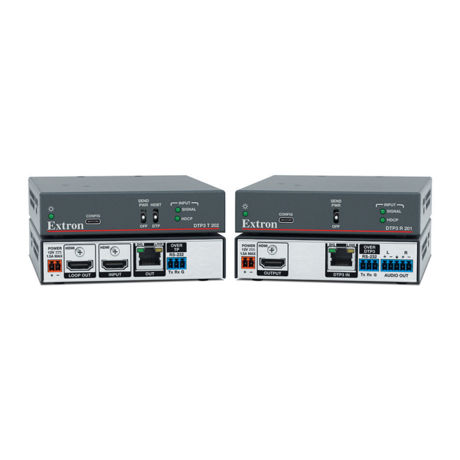
- Page 1 User Guide DTP Systems DTP3 T 202/DTP3 R 201 HDMI Twisted Pair Transmitters and Receivers 68‑3445‑01 Rev. A 07 21...
- Page 2 Safety Instructions...
- Page 3 Copyright © 2021 Extron. All rights reserved. www.extron.com Trademarks All trademarks mentioned in this guide are the properties of their respective owners. ® The following registered trademarks ( ), registered service marks ( ), and trademarks ( ) are the property of RGB Systems, Inc. or Extron (see the current list of trademarks on the Terms of Use page at www.extron.com):...
- Page 4 FCC Class A Notice This equipment has been tested and found to comply with the limits for a Class A digital device, pursuant to part 15 of the FCC rules. The Class A limits provide reasonable protection against harmful interference when the equipment is operated in a commercial environment.
- Page 5 Conventions Used in this Guide Notifications The following notifications are used in this guide: CAUTION: Risk of minor personal injury. ATTENTION : Risque de blessure mineure. ATTENTION: • Risk of property damage. • Risque de dommages matériels. NOTE: A note draws attention to important information. Software Commands Commands are written in the fonts shown here: ^AR Merge Scene,,Op1 scene 1,1 ^B 51 ^W^C...
-
Page 7: Table Of Contents
Device‑initiated Power‑up Message ....17 Error Messages ..........17 Timeout ............17 Symbols Used in this Guide ....... 18 Symbol Definitions ......... 18 Command and Response Table for SIS Commands ............19 DTP3 T 202 / DTP3 R 201 • Table of Contents... - Page 8 DTP3 T 202 / DTP3 R 201 • Table of Contents viii...
-
Page 9: Introduction
4K @ 60 Hz, 4:4:4, supporting data rates up to 18 Gbps. Both units are HDMI (2.0b and 1.4) and HDCP (2.3 and 1.x) compliant. HDCP, and CEC transmission is negotiated from source to sink. The DTP3 T 202 has EDID Minder ®... -
Page 10: Tp Cable Advantages
EDID Minder® automatically manages EDID communication between • connected devices (DTP3 T 202) — EDID Minder ensures that the source powers up properly and reliably outputs content for display. DTP3 T 202 / DTP3 R 201 • Introduction... - Page 11 HDR video. • DTP3 output is compatible with HDBaseT-enabled devices (DTP3 T 202) — The DTP output can be configured to send video and embedded audio, plus bidirectional RS‑232 signals to an HDBaseT‑enabled display.
-
Page 12: Installation And Operation
UP position on the powered DTP3 device to enable sending remote power to the far end DTP3 device. Set the toggle switch to the DOWN position on the DTP3 device receiving power (see figure , on page 11). DTP3 T 202 / DTP3 R 201 • Installation and Operation... -
Page 13: Connections
ATTENTION: • The DTP3 T 202 and DTP3 R 201 devices are configured to output power to DTP3 models only. If connected to a non‑DTP3 device, set the toggle switch to the DOWN (OFF) position. Failure to turn the power OFF will damage the connected device. -
Page 14: Receiver Rear Panel Connections
Link LED — This amber LED indicates a valid link is established between this • receiving device and the transmitter. NOTE: See TP Cable Termination and Recommendations on page 8 to properly wire the RJ‑45 connectors. DTP3 T 202 / DTP3 R 201 • Installation and Operation... - Page 15 S’ils sont trop courts, ils peuvent être tirés facilement, même s’ils sont correctement serrés par les borniers à vis. DTP3 T 202 / DTP3 R 201 • Installation and Operation...
-
Page 16: Securing The Hdmi Connector
N’utilisez pas le câble audiovisuel Skew‑Free UTP version améliorée UTP23SF‑4 Extron ou le câble STP201 pour relier les produits XTP à des émetteurs ou récepteurs DTP3. Le DTP3 ne fonctionne pas correctement avec ces câbles. DTP3 T 202 / DTP3 R 201 • Installation and Operation... -
Page 17: Power Supply Wiring
Separate twisted pair cables from AC power cables. Power Supply Wiring A 12 VDC, 2.0 A power supply is provided with the DTP3 T 202 transmitter. Follow these instructions to wire the 2‑pole captive screw connector to your power supply: CAUTION: Risk of minor personal injury: •... - Page 18 Si le produit n’est pas fourni avec une source d’alimentation, il doit être utilisé avec une source d’alimentation certifiée UL de classe 2 ou LPS avec une tension nominale de 12 Vcc, 1,8 A minimum (DTP3 T 202) ou 12 Vcc, 1,7 A minimum (DTP3 R 201).
-
Page 19: Rs-232 Connector Wiring
— Lights when the unit is receiving power, either locally or remotely (over the Power LED DTP3 cable). DTP3 T 202 Rear Panel DTP3 R 201 Rear Panel DTP3 T 202 / DTP3 R 201 • Installation and Operation LINK OVER LINK OVER... - Page 20 ATTENTION: • The DTP3 T 202 and DTP3 R 201 devices are configured to output power to DTP3 models only. If connected to a non‑DTP3 device, set the toggle switch to the DOWN (OFF) position. Failure to turn the power OFF will damage the connected device.
-
Page 21: Connecting To The Front Panel Usb Port
Connecting a PC to the DTP3 Device Front Panel USB Port If this is the first time the DTP3 device has been connected to the PC, the Found New Hardware Wizard opens (see figure 11). DTP3 T 202 / DTP3 R 201 • Installation and Operation... - Page 22 Windows Update to search the web at this time (for example, if the driver is already on your computer). Click Next ( The next screen of the Wizard opens: Figure 12. Installing the Software Automatically DTP3 T 202 / DTP3 R 201 • Installation and Operation...
-
Page 23: Resetting
Configure the transmitter or receiver as required using SIS Commands (see Configuration and Control starting on page 16). Resetting Use the SIS command to reset the transmitter or receiver to its factory default settings (see Reset on page 22). DTP3 T 202 / DTP3 R 201 • Installation and Operation... -
Page 24: Sis Configuration And Control
SIS Configuration and Control Use Simple Instruction Set (SIS) commands to configure the DTP3 T 202 transmitter and DTP3 R 201 receiver. This section provides information about using those commands. The following topics are discussed: Host Control Port • • Simple Instruction Set Control •... -
Page 25: Simple Instruction Set Control
— Invalid command — Invalid parameter Timeout Pauses of 10 seconds or longer between command ASCII characters result in a timeout. The command operation is aborted with no other indication. DTP3 T 202 / DTP3 R 201 • SIS Configuration and Control... -
Page 26: Symbols Used In This Guide
2 = Video/source detected, with HDCP = Output HDCP Status 0 = No sink detected 1 = Sink detected, output not HDCP encrypted 2 = Sink detected, output HDCP encrypted DTP3 T 202 / DTP3 R 201 • SIS Configuration and Control... -
Page 27: Command And Response Table For Sis Commands
HDCP Authorized Device (Tx only) HDCP authorization enable/ HDCP HdcpE disable HDCP authorization status EHDCP HdcpE Verbose mode 2/3 = Authorization status 0 = Disabled 1 = Enabled (default) KEY: DTP3 T 202 / DTP3 R 201 • SIS Configuration and Control... - Page 28 View verbose mode Verbose mode 0 = Clear/none (default) 1 = Verbose mode 2 = Tagged responses for queries KEY: 3 = Verbose mode and tagged responses for queries DTP3 T 202 / DTP3 R 201 • SIS Configuration and Control...
- Page 29 A user password cannot be assigned if no administrator password exists; the E14 error code is returned. If the administrator password is cleared, the user password is also removed. DTP3 T 202 / DTP3 R 201 • SIS Configuration and Control...
- Page 30 The factory configured passwords for all accounts on this device have been set to the device serial number. In the event of a complete system reset, the passwords convert to the default, which is extron (see Password on page 21 for more information). DTP3 T 202 / DTP3 R 201 • SIS Configuration and Control...
-
Page 31: Downloading And Updating Firmware
Software Page with Alphabetic Navigation Bar On the bottom of the page, click on the F link (see figure 15, Locate Firmware Loader (see figure 16 on the next page). DTP3 T 202 / DTP3 R 201 • SIS Configuration and Control... -
Page 32: Installing Firmware Loader
(see figure 17, Figure 17. Locate Firmware for DTP3 Transmitter or Receiver Click Firmware in the drop‑down list ( The Firmware page opens (see figure 18 on the next page). DTP3 T 202 / DTP3 R 201 • SIS Configuration and Control... -
Page 33: Updating Firmware On A Dtp3 Device
Start > All Programs > Extron Electronics > Firmware Loader > Firmware Loader The Firmware Loader window opens. The Add Device... window opens in front (see figure 19). Figure 19. Opening Firmware Loader DTP3 T 202 / DTP3 R 201 • SIS Configuration and Control... - Page 34 Connected Device section, followed by a check mark ( Figure 20. Add Device Window ) in the New Firmware File (Optional) section. Click the Browse button ( DTP3 T 202 / DTP3 R 201 • SIS Configuration and Control...
- Page 35 On the Add Device... window, the path to the new firmware file is displayed in the Path field (see figure 22, Figure 22. Path to New Firmware File on the Add Device Window DTP3 T 202 / DTP3 R 201 • SIS Configuration and Control...
- Page 36 The Total Progress section displays a progress bar with Uploading... • above it. In the Device section, the Progress column displays an incrementing • percentage and another progress bar. The Status column displays Uploading..• DTP3 T 202 / DTP3 R 201 • SIS Configuration and Control...
- Page 37 ) and in the Status column ( DTP3 T 202 60-1869-52 1.00.001 dtp3t202_A_v1.00.00... Extron USB Devi... Completed Figure 26. Firmware Upload Complete Close the Firmware Loader window when the upload is complete. DTP3 T 202 / DTP3 R 201 • SIS Configuration and Control...
-
Page 38: Product Configuration Software
Software Overview • NOTE: In this section, you see screenshot examples showing the DTP3 R 201 device. DTP3 T 202 screens are virtually the same except for the product name. Software Installation Extron website, locate it on the Download Center page or go To download PCS from the to the PCS product page. -
Page 39: Connecting To Pcs
Open PCS on the control PC from the PCS icon loaded on the desktop or from the Start menu click Start > Programs > Extron Electronics > Extron Product Configuration Software. PCS opens to the Device Discovery screen (figure 29). -
Page 40: Tcp/Ip Panel
), enter the connected port or leave the field blank. PCS scans for the port if blank. Click the Connect button ( ). The device main page opens (see figure 31 on the next page). DTP3 T 202 / DTP3 R 201 • Product Configuration Software... -
Page 41: Software Overview
NOTE: For details about specific software features and to control the device using PCS, see the device PCS help file. The Product Configuration Software opens to the device main page (DTP3 T 202 shown for example) (see figure 31). Figure 31. -
Page 42: Pcs Software Menu
Selecting Show Expanded Device Tabs (see ) from the Software menu displays figure 33, the device IP address in the Device tab (see figure 34). Figure 34. Expanded Device Tab DTP3 T 202 / DTP3 R 201 • Product Configuration Software... - Page 43 Open the PCS help file for general PCS operations. From the Software menu, select Extron PCS Help (see figure , on the previous page). The Help file opens (see figure 36). Figure 36. PCS Help Main Window DTP3 T 202 / DTP3 R 201 • Product Configuration Software...
-
Page 44: Updating Firmware Using Pcs
Alternatively, click the Cancel button ( ) to leave the software open. Updating Firmware Using PCS Firmware for the device can be updated using PCS (see the device PCS help file). DTP3 T 202 / DTP3 R 201 • Product Configuration Software... -
Page 45: Reference Information
Reduced air flow — Installation of the equipment in a rack should be such that the amount of air flow required for safe operation of the equipment is not compromised. DTP3 T 202 / DTP3 R 201 • Reference Information... - Page 46 Reliable earthing (grounding) — Reliable earthing of rack‑mounted equipment should be maintained. Particular attention should be given to supply connections other than direct connections to the branch circuit (such as use of power strips). DTP3 T 202 / DTP3 R 201 • Reference Information...
-
Page 47: Extron Warranty
Extron Warranty Extron warrants this product against defects in materials and workmanship for a period of three years from the date of purchase. In the event of malfunction during the warranty period attributable directly to faulty workmanship and/ or materials, Extron will, at its option, repair or replace said products or components, to whatever extent it shall deem necessary to restore said product to proper operating condition, provided that it is returned within the warranty period, with proof of purchase and description of malfunction to: USA, Canada, South America,...