
Related Manuals for Extron electronics FOX II T DP 4K


Summary of Contents for Extron electronics FOX II T DP 4K
- Page 1 User Guide Fiber Optic Extenders FOX II T DP 4K FOX II R DP 4K Fiber Optic Transmitter and Receiver for DisplayPort 68-2540-01 Rev. D 01 19...
- Page 2 Safety Instructions Safety Instructions • English Istruzioni di sicurezza • Italiano WARNING: This symbol, , when used on the product, is intended to AVVERTENZA: Il simbolo, , se usato sul prodotto, serve ad alert the user of the presence of uninsulated dangerous voltage within avvertire l’utente della presenza di tensione non isolata pericolosa the product’s enclosure that may present a risk of electric shock.
- Page 3 より 『Extron Safety www.extron.com and Regulatory Compliance Guide』 (P/N 68-290-01) をご覧ください。 Copyright © 2019 Extron Electronics. All rights reserved. Trademarks All trademarks mentioned in this guide are the properties of their respective owners. The following registered trademarks®, registered service marks( ), and trademarks( ) are the property of RGB Systems, Inc.
- Page 4 This interference must be corrected at the expense of the user. Class 1 Laser Product Any service to this product must be carried out by Extron Electronics and its qualified service personnel. CAUTION: Using controls, making adjustments, or performing procedures in a manner other than what is specified herein may result in hazardous radiation exposure.
- Page 5 Software Commands Commands are written in the fonts shown here: ^AR Merge Scene,,Op1 scene 1,1 ^B 51 ^W^C [01] R 0004 00300 00400 00800 00600 [02] 35 [17] [03] E X! *X1@* XX1** X1** X2! NOTE: For commands and examples of computer or device responses mentioned in this guide, the character “0”...
-
Page 7: Table Of Contents
Contents Introduction ............1 Remote Control ........... 17 About this Guide ..........2 Simple Instruction Set Control ......17 About the FOX II T/R DP 4K Transmitter and Host-to-Unit Instructions ....... 17 Receiver ............3 Unit-Initiated Messages ........ 18 Transmitter............3 Error Responses ........... - Page 8 FOX II T/R DP 4K Transmitter and Receiver • Contents viii...
-
Page 9: Introduction
Introduction WARNING: The FOX II T/R DP 4K outputs continuous invisible light (Class 1 rated), which may be harmful to the eyes; use with caution. AVERTISSEMENT : Le FOX II T/R DP 4K émet une lumière invisible en continu (conforme à la classe 1) qui peut être dangereux pour les yeux, à utiliser avec précaution. -
Page 10: About This Guide
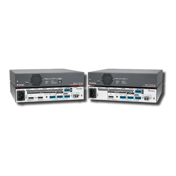
About this Guide This guide contains information about the ultra-high performance Extron FOX II T/R DP 4K transmitter and receiver, a fiber optic extender (see figure 1). Extron T DP 4K Fiber Optic Transmitter Extron IPCP Pro 250 IP Link Pro Control Processor Ethernet L I/O... -
Page 11: About The Fox Ii T/R Dp 4K Transmitter And Receiver
Transmitter The FOX II T DP 4K transmitter accepts DisplayPort video, at a resolution of up to 4K (4096x2160 at 30 Hz). The video input can also include embedded audio. The transmitter also loops the DisplayPort input through for a local monitor. -
Page 12: System Compatibility
The transmitter and receiver are further categorized by the type of fiber optic cable, multimode or singlemode, which define the effective range of transmission: Multimode — Long distance, up to 2 km (6,560 feet) (depending on the fiber cable) FOX II T DP 4K MM • •... - Page 13 Audio embedding — Converts analog stereo audio signals to digital DP audio when • the analog input is selected. Two analog audio inputs — The transmitter accepts an unbalanced stereo or mono • audio input on a 3.5 mm mini jack and a balanced or unbalanced stereo or mono audio on a 5-pole captive screw connector.
-
Page 14: Installation And Operation
RESET DISPLAYPORT LOOP THRU Tx Rx G 1 OPTICAL 50-60 Hz Figure 2. FOX II T DP 4K Transmitter Rear Panel Connectors DisplayPort input port (see page 7) Remote RS-232 port (see page 7) Loop-Thru port Alarm port (see page 7) - Page 15 DisplayPort input port (see figure 2 on the previous page) — Connect a digital video input to this DisplayPort connector. The transmitter also accepts DISPLAYPORT embedded digital audio on this connector. Loop-through port — If desired, connect a local monitor to this DisplayPort connector.
- Page 16 Fiber optic ports and LEDs (see figure 2 on page 6) — WARNING: The FOX II R DP 4K outputs continuous invisible light (Class 1 rated), which may be harmful to the eyes; use with caution. Plug the attached dust cap into the optical transceiver when the fiber optic cable is unplugged.
- Page 17 Plug the attached dust cap into the optical transceiver when the fiber optic cable is unplugged. AVERTISSEMENT : Le FOX II T DP 4K émet une lumière invisible en continu (conforme à la classe 1) qui peut être dangereux pour les yeux, à utiliser avec précaution Branchez la protection contre la poussière dans l’ensemble émetteur/...
- Page 18 DisplayPort output port (see figure 3 on the previous page) — Connect a video display to this DisplayPort connector. DISPLAYPORT Audio output ports — These connectors output the transmitted, AUDIO unamplified, line level analog audio (see Audio connections page 12 to wire these connectors). NOTE: If embedded digital audio is present on the DP connector, these analog audio connectors do not output audio unless forced to so by an SIS command...
-
Page 19: Front Panel Configuration Port
• Do not exceed 6.5 feet (2 meters) of cable on the input or buffered loop-through of the FOX II T DP 4K transmitter or the output of the FOX II R DP 4K receiver. • Use only the cable specifically designed and intended for high speed digital signals that is supplied by Extron. - Page 20 Audio connections NOTE: The level of the analog audio inputs can be set via an SIS command (see Analog page 21) or using the software slide control (see the Analog Input Gain Input control, , in “Product Configuration Software” on page 32). The following table shows the audio format that is sent over the fiber connection, along with the DisplayPort video, when the audio input format is set to (the default setting, see...
- Page 21 Captive screw output connection See figure 7, below, to properly wire a captive screw output connector, either audio output on the receiver or return audio output on the transmitter. The connector is included with transmitter and receiver, but you must supply the audio cable. Use the supplied tie-wrap to strap the audio cable to the extended tail of the connector.
-
Page 22: Indications And Operation
Indications and Operation Front Panel Features VIDEO AUDIO EDID SELECT SIGNAL INPUT CONFIG HDCP RETURN OUT T DP 4K DISPLAYPORT FIBER OPTIC TRANSMITTER Transmitter VIDEO AUDIO SIGNAL OUTPUT CONFIG HDCP RETURN IN R DP 4K DISPLAYPORT FIBER OPTIC RECEIVER Receiver Figure 9. -
Page 23: Rear Panel Features
EDID Select rotary switch (see figure 9 on the previous page) — Set this EDID SELECT switch to one of the positions below to select the source of the DDC or a specific resolution. Position 0 — A user-recorded EDID that has been previously: •... -
Page 24: Operation
Operation After the transmitter, the receiver, and their connected devices are powered up, the system is fully operational. If any problems are encountered, verify that the cables are routed and connected properly, and that all display devices have identical resolutions and refresh rates. If your problems persist, call the Extron S3 Sales &... -
Page 25: Remote Control
Remote Control This section describes the remote control operation of the FOX II T/R DP 4K transmitter and receiver, including: • Simple Instruction Set Control • Product Configuration Software The transmitter and receiver each have a front panel Configuration port, a USB mini-B connector (see Configuration Port on page 11) and a rear panel Remote RS-232 port, a... -
Page 26: Unit-Initiated Messages
When a local event, such as an equipment power-up, occurs, the unit responds by sending a message to the host. The unit-initiated messages are listed below: •, x.xx, (c) Copyright 20nn Extron Electronics FOX II T DP 4K YY 60-nnnn-xx - or - •, x.xx,... -
Page 27: Using The Command And Response Tables
Using the Command and Response Tables next page. The The command and response table for the transmitter begins on the command and response table for the receiver begins on page 23. Uppercase and lower case letters are acceptable in the command field except where indicated for the audio level (gain and attenuation) commands. -
Page 28: Command And Response Table For Transmitter Sis Commands
Command and Response Table for Transmitter SIS Commands Command SIS Command Response Additional description (host to unit) (unit to host) EDID Minder Resolution NOTE: • The front panel HEX switch must be in position 1 for the AEDID commands to be effective. In any other position, the transmitter returns the E14 error code. - Page 29 Command and Response Table for Transmitter SIS Commands (continued) Command SIS Command Response Additional description (host to unit) (unit to host) Input reports as an HDCP authorized device HDCP authorized device on Set the transmitter as an HDCP-authorized device E1HDCP HdcpE1 (default).
- Page 30 Command and Response Table for Transmitter SIS Commands (continued) Command SIS Command Response Additional description (host to unit) (unit to host) Transmitter name Assign a name to the device EX1@ X1@] Ipn• Name the transmitter Reset device name to default •CN Ipn•FOX-II-T-DP-4K View the device name...
-
Page 31: Symbol Definitions For Receiver Sis Commands
Symbol Definitions for Receiver SIS Commands = CR/LF (carriage return/line feed) = Carriage return (no line feed) = Pipe (can be used interchangeably with the character) • = Space (hard) character = Escape key (hex 1B) W = Can be used interchangeably with the character = Video and sync mute status 0 = off... - Page 32 Command and Response Table for Receiver SIS Commands (continued) Command SIS Command Response Additional description (host to unit) (unit to host) Audio mute Mute the audio Silence the receiver DisplayPort audio. Example: Silence the DisplayPort audio. 1*1Z Amt1*1 Unmute the audio The transmitter outputs DisplayPort audio, analog audio, or both.
-
Page 33: Product Configuration Software
Product Configuration Software The Extron Product Configuration Software, which communicates with the connected transmitter or receiver via the front panel Configuration port (see Configuration Port page 11) of that unit, provides an easy way to operate and configure the unit. The program is compatible with Windows 7, 64-bit, or later. - Page 34 Program Files Extron directory, and it places the following four icons into a group folder named Extron PCS “ ” Extron Electronics Extron Product Configuration Software: NOTE: ... for 64-bit operating systems. Program Files(x86)\ • Check for Extron PCS Updates •...
-
Page 35: Starting The Program
Starting the Program Start the Extron Product Configuration Software as follows: Click > > > Start Programs Extron Electronics Extron Product Configuration > Software Extron Product Configuration Software The Product Configuration Software opens to the window Device Discovery (see figure 13). -
Page 36: Using The Software
Using the Software Once you have connected to a device, the window (see figure 14 for the transmitter Status and figure 15 for the receiver) is the default start-up window for the Product Configuration Software. The window provides indications of the connection status. Status window Figure 14. - Page 37 Video Signal Presence indicators (see figure 14 and figure 15 on the previous page) Transmitter connection — Indicates green ( ) when the transmitter detects a sync signal on its DisplayPort video input. Receiver connection — Indicates green ( ) when the receiver detects a digital video signal on its fiber optic input.
- Page 38 EDID Minder window (connected to transmitter only) window (see figure 16) provides controls for you to tailor the EDID that is EDID Minder provided to the transmitter. Select this window from either the Status Input/Output window by clicking on the menu bar. Configuration EDID Minder NOTE: The transmitter front panel EDID Select rotary switch must be in the 1 position...
- Page 39 Input/Output Configuration window window allows you to set the input and output option Input/Output Configuration features of the transmitter (see figure 17) and receiver (see figure 18, on page 33). Select this window from either the window by clicking Status EDID Minder Input/Output on the menu bar.
- Page 40 radio buttons (see figure 17 on the previous page) — HDCP Notification Select either the radio button to select how the transmitter Green Black displays HDCP notification on a monitor connected to its Loop-through output port. The HDCP notification function in the transmitter enables a connected display to show a green or black screen if the transmitted video is HDCP encrypted, and the display is not HDCP capable.
- Page 41 Receiver Input/Output Configuration window Figure 18. Input/Output Configuration Screen for the Receiver radio buttons — Select the radio button for the receiver HDCP Mode Auto to follow the input video HDCP encryption status on the DisplayPort connector. Select to always encrypt the output video regardless if the input video is encrypted or not.
- Page 42 slide control (see figure 18 on the Return Audio Input Gain previous page) — Click and slide the slide Return Audio Input Gain control to vary to select the input audio gain or attenuation value of the audio returned to the transmitter, from -18 dB to +24 dB in 1 dB increments.
-
Page 43: Device Menu (Both Units)
Device Menu (Both Units) The device menu is accessed by clicking the icon on the device tab above the menu bar. • — Disconnects the Product Configuration Software Disconnect from the unit while leaving the program active. • — Opens the dialog box Settings Unit Information... -
Page 44: Updating The Firmware
Updating the Firmware The Product Configuration Software can open the Firmware Loader utility, which provides a way to replace the transmitter or receiver firmware without taking the unit out of service. NOTE: Upgrading the firmware does not overwrite the current configuration. Update the unit firmware as follows: Perform steps 1 through 7 of Installing the... - Page 45 Folder where firmware is installed. Sample location only. Figure 22. Downloading Firmware Upgrade Files FOX II T/R DP 4K Transmitter and Receiver • Remote Control...
- Page 46 Start the Product Configuration Software and connect to the unit (see Starting the Program on page 27). On the device tab, click > . An dialog box Update firmware Update Firmware opens, and the software asks you to confirm that you want to disconnect it from the unit (see figure 21).
- Page 47 Click (see figure 23, 4 on the previous page). Update The software advises you that you are about to reprogram the unit firmware. Click continue. The Firmware Loader utility tests the connection, installs the update, and then verifies the firmware. At the conclusion of the process, the utility reports and prompts you to reconnect Update Complete...
-
Page 48: Unit Mounting
Unit Mounting Mounting the Units ATTENTION: • Installation and service must be performed by authorized personnel only. • L’installation et l’entretien doivent être effectués par le personnel autorisé uniquement. Either of the 1U high, half-rack width units can be placed on a tabletop or mounted on a rack shelf, or under or through a desk or other furniture. - Page 49 Extron Electronics makes no further warranties either expressed or implied with respect to the product and its quality, performance, merchantability, or fitness for any particular use. In no event will Extron Electronics be liable for direct, indirect, or consequential damages resulting from any defect in this product even if Extron Electronics has been advised of such damage.