
Related Manuals for Trane City RTSF050


Summary of Contents for Trane City RTSF050
- Page 1 Installation Operation Maintenance Water-cooled Liquid Chillers with Helical Rotary Compressors RTSF: 180-385kW (R1234ze) RLC-SVX023A...
- Page 2 Additional services ..................47 FWD: *water temperature: max 100° C *absolute service pressure: min 1 bar/max 11 bars Accessories - Hot water coil: *water temperature: min. +2° C/max. 100° C *absolute service pressure: min 1 bar/max 11 bars UNT-PRC002-GB © Trane 2019 RLC-SVX023A...
-
Page 3: Safety Recommendations
Specify any visible damage on the delivery note, by the user, of Trane City chiller RTSF , manufactured in and send a registered letter of protest to the last carrier Sound power levels France. -
Page 4: Maintenance Contract
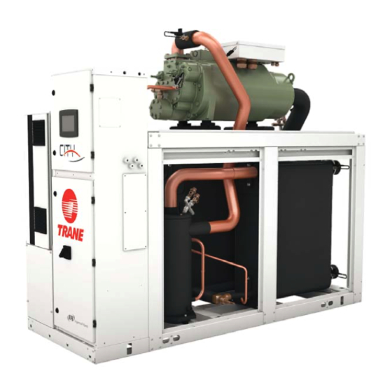
The RTSF units are helical-rotary type, water-cooled, It is strongly recommended that you sign a maintenance liquid chillers, designed for installation indoors. contract with your local Trane Service Agency. This The RTSF units are packaged with an evaporator contract provides regular maintenance of your and condenser. -
Page 5: Unit Model Number Description
Unit model number description Digit 1, 2, 3, 4 – Unit Model Digit 27 – Not Used RTSF Digit 28 – Evaporator pump Digit 5, 6, 7 – Unit size X = Without 50 = 50 Nominal tons Digit 29 – Condenser Size 60 = 60 Nominal tons Sound power levels 70 = 70 Nominal tons... - Page 6 Unit model number description Technical Data Digit 45 – Energy meter X = Without M = With Digit 46 – Condenser Pump Smart Flow Control/Other Condenser Pressure Control Outputs X = Without Power supply (V/Ph/Hz) 230/1/50 1 = Condenser Pressure in % HPC Capacities 2 = Differential Pressure Cooling capacity on water (1)
-
Page 7: General Data
General Data Table 1 – General Data RTSF Standard efficiency - R1234ze RTSF050 RTSF060 RTSF070 RTSF090 RTSF100 RTSF110 Indicative performances (1) Cooling Capacity (1) (kW) Total Power input in cooling (1) (kW) Sound power levels Unit Electrical data (2) (5) Low VI compressor - digit 20 =L Maximum Power Input (kW) -
Page 8: Unit Description
Unit Description Technical Data Component location for typical RTSF Unit 2 = Power cable gland plate for customer wiring 4 = Suction line 5 = Oil separator Power supply (V/Ph/Hz) 230/1/50 6 = Condenser water outlet Capacities Cooling capacity on water (1) (kW) 18,8 30,1... - Page 9 FWD 20 condenser, to isolate the heat exchangers for maintenance and to balance/trim the system. Intake Table 2 – Installation Responsibility Measurement conditions: Trane supplied Trane supplied Customer supplied Measurements taken at the horizontal air intake. Requirement Trane installed Field installed...
-
Page 10: Installation - Mechanical
14,1 16,5 at 10 °C), call a qualified service organization and the NOTE: Required vertical clearance above the unit is at Air flow appropriate Trane sales office. minimum 1400 1800 2700 least 1 m. There should be no piping or conduit located NOTE: Pressure will be approximately 1.0 bar if shipped... -
Page 11: Handling Procedure
IL EST RECOMMANDE D'UTILISER LES ORGANES DE LEVAGE ET DE MANUTENTION MONTRES PAR LE SCHEMA ET DE SUIVRE LES INSTRUCTIONS SUIVANTES : 1 -ATTENTION : CETTE UNITE DOIT ETRE LEVEE ET MANUTENTIONNEE AVEC PRECAUTIONS. EVITER LES A-COUPS LORS DU LEVAGE ET DE LA MANUTENTION. ANWEISUNGEN FUER DEN TRANSPORT MIT HEBEZEUG ES WIRD EMPFOHLEN, DIE MASCHINE ENTSPRECHEND DER ZEICHNUNG MIT EINEM KRAN ANZUHEBEN UND DIE FOLGENDEN ANWEISUNGEN ZU BEACHTEN :... -
Page 12: Unit Leveling
Installation - Mechanical Technical Data Unit Leveling Water Treatment NOTE: The electrical panel side of the unit is designated WARNING: Do not use untreated or improperly treated water. Use of untreated or improperly treated water may as the “front” of the unit. result in equipment damage. -
Page 13: Evaporator Piping Components
Installation - Mechanical Evaporator Piping Components Condenser Piping Components Note: Make sure all piping components are between the “Piping components” include all devices and controls shutoff valves, so that isolation can be accomplished used to provide proper water system operation and unit on both the condenser and the evaporator. -
Page 14: Water Pressure Relief Valves
Installation - Mechanical Technical Data Water Pressure Relief Valves Refrigerant Pressure Relief Valve Venting Install a pressure relief valve in both evaporator and condenser water systems. Failure to do so could result To prevent injury due to inhalation of refrigerant gas, do in Heat Exchanger damage. - Page 15 Installation - Mechanical RTSF condensers Pressure drop on waterside RTSF condensers Pressure drop on waterside 1000 Sound power levels Discharge Measurement conditions: Measurements taken in a room adjacent to the room containing the FWD, at the outlet of the rectangular duct (1.5 m long) fixed to its discharge opening.
-
Page 16: Freeze Protection
LERTC limit. Height (mm) • Maintain refrigerant charge at appropriate levels. If Shipped unit dimensions Width x Depth charge is in question, contact Trane service. A reduced (mm) 933 x 644 1133 x 754 1333 x 864 1333 x 1008... - Page 17 For information on 3. The minimum low refrigerant cutout set point allowed is - 20.6°C. specific conditions, contact Trane. This minimum is established by the solubility limits of the oil in the refrigerant.
- Page 18 0,46 0,65 1,04 1,51 available. To control a 2-way or 3-way valve, Trane offers Methods other than those shown can be employed to Current amps (3) a Condenser Regulating Valve Control option for the achieve the same results. Contact your local Trane office...
- Page 19 Installation - Mechanical Cooling device bypass – Figure 3 Condenser water pump with variable frequency drive – Figure 4 Cooling device bypass is also a valid control method if the chiller temperature requirements can be maintained. Advantages: Advantage: • Pumping cost can be reduced. Good cooling device Sound power levels temperature control.
-
Page 20: Condenser Water Regulating Valve Adjustment
Installation - Mechanical Technical Data Condenser Water Regulating Valve Adjustment A separate Settings Menu tab entitled “Condenser Head Pressure Control -Setup” that is only visible if Power supply (V/Ph/Hz) 230/1/50 the configuration is selected, contain the following Capacities settings and manual overrides for user adjustments and Cooling capacity on water (1) (kW) 18,8... -
Page 21: Installation - Electrical
• For variable frequency drives or other energy storing the unit. Measurements taken at the horizontal air intake. components provided by Trane or others, refer to the Do not allow conduit to interfere with other components, appropriate manufacturer’s literature for allowable Power level in dB(A), per Hz frequency band structural members or equipment. -
Page 22: Power Supply Wiring
Installation - Electrical Technical Data Power Supply Wiring Compressor Motor Phase Sequencing Model RTSF chillers are designed according to European standard EN 60204-1; therefore, all power supply wiring Always verify that proper rotation of the chiller must be sized and selected accordingly by the project compressor is established before the machine is started. -
Page 23: Interconnecting Wiring (Field Wiring Required)
Installation - Electrical Interconnecting Wiring (Field Wiring Required) Important: Do not turn chiller on or off using the chilled Sound power levels water pump interlocks. When making field connections, refer to the appropriate Discharge field layout, wiring, schematics and controls diagrams that ship with the unit. - Page 24 586x321x8 586*421*8 586*621*8 and closings of the switch due to turbulent water flow, your local Trane service). The events/states that can be G4 filter (filter box accessory) etc. This shall be accomplished with a 6 seconds filtering Quantity assigned to the programmable relays are listed in the time.
- Page 25 Installation - Electrical The Tracer UC800 Service Tool (TU) is used to install and assign any of the above listed events or status to each of the 4 relays. The default assignments for the 4 available relays are listed below. Sound power levels LLID Software LLID Name...
- Page 26 Installation - Electrical Technical Data LonTalk Communication Interface - Optional Percent Condenser Pressure Output - Optional Tracer UC800 provides an optional LonTalk Tracer UC800 provides a 2-10 VDC analog output to Communication Interface (LCI-C) between the chiller and indicate condenser pressure in percent of software High a BAS.
-
Page 27: Operating Principles Mechanical
RTSF chillers equipped with The refrigeration cycle of the chiller is conceptually microcomputer-based control systems. It describes the similar to that of other Trane chiller products. It makes overall operating principles of the design. Following use of a BPHE evaporator. - Page 28 Operating Principles Mechanical Technical Data Cycle Description Cooling device water, circulating through the condenser plates, absorbs heat from this refrigerant and The refrigeration cycle for the chiller can be described condenses it. using the pressure-enthalpy diagram shown in Figure 5. Key State Points are indicated on the figure Refrigerant leaves the condenser as subcooled liquid and and are referenced in the discussion following.
-
Page 29: Refrigerant Flow Diagram
Operating Principles Mechanical Refrigerant flow diagram Refrigerant flow diagram for unit is supplied with drawing package with unit order. Figure 6 – Example of typical refrigerant flow diagram Sound power levels Discharge Measurement conditions: Measurements taken in a room adjacent to the room containing the FWD, at the outlet of the rectangular duct (1.5 m long) fixed to its discharge opening. - Page 30 Operating Principles Mechanical Technical Data Compressors Slide Valve movement Slide valve operates coordinated with AFD. Tracer UC800 The compressor used by the chiller consists of 3 distinct algorithm controls the compressor capacity with higher sections: the motor, the rotors and the bearing housing. slide valve capacity and lower AFD frequency to get Compressor Motor higher efficiency...
- Page 31 Operating Principles Mechanical Figure 7 – Compressor description Sound power levels A = Oil control valve (hidden) B = Female unloader piston Discharge C = Discharge check valve D = Female rotor Measurement conditions: E = Motor terminals Measurements taken in a room adjacent to the room containing the FWD, at the outlet of the rectangular duct (1.5 m F = Suction strainer long) fixed to its discharge opening.
-
Page 32: Oil Management System
Operating Principles Mechanical Technical Data Oil Management System Oil Filter All chillers are equipped with replaceable-element oil Oil Separator filters. Each removes any impurities that could foul The oil separator consists of a vertical tube, joined the compressor internal oil supply galleries. This also at the top by the refrigerant discharge line from the prevents excessive wear of compressor rotor and Power supply... - Page 33 Typical Operating map Figure 8 – Typical operating map Sound power levels Discharge Measurement conditions: Measurements taken in a room adjacent to the room containing the FWD, at the outlet of the rectangular duct (1.5 m long) fixed to its discharge opening. Power level in dB(A), per Hz frequency band Overall power Unit...
-
Page 34: Controls Overview
Weight (kg) tasks and setpoint changes. However to adequately Colour galvanised steel service chiller, Tracer™ TU service tool is required Recommended fuse size (Non-Trane personnel, contact your local Trane office Unit alone (aM/gI) 8/16 8/16 8/16 8/25 8/25 Unit with electric heater (gI) -
Page 35: Pre-Start Checkout
Installation section. treatment specialist be engaged to determine what 12. Check and set, as required, all UC800 TD7 menu water treatment, if any, is required. Trane assumes no Discharge items. responsibility for equipment failures which result from 13. -
Page 36: Unit Voltage Phasing
Pre-Start Checkout Technical Data Unit Voltage Phasing WARNING! It is imperative that L1, L2, and L3 in the starter be connected in the A-BC phase sequence to It is important that proper rotation of the compressors prevent equipment damage due to reverse rotation. be established before the unit is started. -
Page 37: Daily Unit Start Up
Unit Start-up Daily Unit Start Up Seasonal Unit Startup Procedure The timeline for the sequence of operation begins with a Close all valves and reinstall the drain plugs in the power-up of the main power to the chiller. The sequence evaporator and condenser. -
Page 38: Periodic Maintenance
Periodic Maintenance Technical Data Overview NOTE: Optimum condenser pressure is dependent on condenser water temperature, and should equal the This section describes preventative maintenance saturation pressure of the refrigerant at a temperature 1 procedures and intervals. Use a periodic maintenance to 3°C above that of leaving condenser water at full load. -
Page 39: Annual Maintenance
Periodic Maintenance Table 5 – Operating Conditions at Minimum Load R1234ze Description Condition Evaporator approach *< 4°C (non-glycol applications) Condensing approach *< 4°C Sound power levels Subcooling 1-2°C Discharge EXV percent open 10-20% open Measurement conditions: * 0.5°C for new unit. Measurements taken in a room adjacent to the room containing the FWD, at the outlet of the rectangular duct (1.5 m long) fixed to its discharge opening. - Page 40 Date____________________________________________________________________. * Return this completed checklist to your Trane Service office as soon as possible to enable the start-up visit to be scheduled. Be aware that advance notification is required to allow scheduling of the start-up as close to the requested date as possible.
-
Page 41: Maintenance Procedures
FWD 10 Trane Polyolester Oil is the approved oil for the unit. Polyolester oil is extremely hygroscopic meaning it FWD 12 readily attracts moisture. The oil can not be stored in plastic containers due to the hygroscopic properties. -
Page 42: Oil Level Check
Maintenance Procedures Technical Data Table 6 - POE Oil Properties Description Acceptable Levels Moisture content less than 300 ppm Acid Level less than 0.5 TAN (mg KOH/g) Power supply (V/Ph/Hz) 230/1/50 Capacities Cooling capacity on water (1) (kW) 18,8 30,1 Heating capacity on water (2) (kW) 11,9... -
Page 43: Removing Compressor Oil
Maintenance Procedures Removing Compressor Oil Replacing the Main Oil Filter (Hot Filter) The oil in the compressor oil separator is under a constant positive pressure at ambient temperature. To The filter element should be changed if the oil flow is remove oil, open the service valve located on the bottom Sound power levels sufficiently obstructed. - Page 44 Maintenance Procedures Technical Data Figure 10 – Oil Filter Replacement Chart Clean Filter Versus Recommended Filter Replacement GP2 / RTWD Clean Filter Versus Recommended Filter Replacement Line UC800 RTSF Pressure Protection Scheme Line CH530 RTWD Oil Pressure Protection Scheme Power supply (V/Ph/Hz) 230/1/50 Capacities...
-
Page 45: Refrigerant Charge
Maintenance Procedures Refrigerant Charge Evacuation and Dehydration 1. Disconnect ALL power before/during evacuation. If a low refrigerant charge is suspected, first determine 2. Connect the vacuum pump to the ½’’ service valves on the cause of lost refrigerant. Once the problem is the oil separator and on the liquid line. -
Page 46: Recommended Service Routine Frequencies
As a commitment to our customers, we have created a wide service network staffed with experienced factory- authorized technicians. At Trane we offer all the benefits of after sales service direct from the manufacturer and we are committed to our mission statement to provide efficient customer care. -
Page 47: Additional Services
Additional services Oil analysis Annual cooling tower maintenance Trane Oil Analysis is a predictive tool used to detect This Service includes the inspection and maintenance of minor issues before they become major problems. It also the cooling tower at least once a year. - Page 48 HVAC systems, comprehensive building services and parts. For more information visit www.Trane.eu Trane has a policy of continuous product and product data improvement and reserves the right to change design and specifications without notice. © 2019 Trane All rights reserved We are committed to using environmentally conscious print practices that reduce waste.