Table of Contents
Advertisement
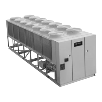
Air-Cooled
®
Series R
Rotary Liquid
Chillers
"CO" and Later Design Sequence
Packaged Air-Cooled Chiller,
RTAA 130-400
Remote Evaporator Air-Cooled Chiller,
RTAA 130-200
Installation
Operation
Maintenance
Library
Product Section
Product
Model
Literature Type
Sequence
Date
File No.
Supersedes
Models
RTAA-130
RTAA-170
RTAA-140
RTAA-185
RTAA-155
RTAA-200
Since The Trane Company has a policy of continuous product improvement, it reserves the right to change
specifications and design without notice. The installation and servicing of the equipment referred in this booklet
should be done by qualified, experienced technicians.
RTAA-IOM-3
Service Literature
Refrigeration
Rotary liquid Chillers – Air-Cooled
Installation, Operation, Maintenance
December 1991
SV-RF-RLC-RTAA-IOM-3-1291
RTAA-240
RTAA-270
RTAA-300
Part No. X39560468-01
RTAA
3
RTAA-340
RTAA-370
RTAA-400
Advertisement
Table of Contents

Related Manuals for Trane RTAA-130


Summary of Contents for Trane RTAA-130
- Page 1 RTAA-400 Part No. X39560468-01 Since The Trane Company has a policy of continuous product improvement, it reserves the right to change specifications and design without notice. The installation and servicing of the equipment referred in this booklet should be done by qualified, experienced technicians.
- Page 2 ©American Standard Inc. 1991...
-
Page 3: Table Of Contents
Table of Contents World environmental scientists have General Information 47 Installation - Mechanical, concluded, based on the best currently Literature Change History Remote Evaporator available evidence, that ozone in our Unit Identification Interconnecting Refrigerant upper atmosphere is being reduced Unit Inspection Piping due to release of CFC fully halogenated Inspection Checklist... - Page 4 77 Operating Principles - 121 Pre-Start Check-out Mechanical 121 General 122 Unit Voltage Power Supply 77 General 122 Unit Voltage Imbalance 77 Refrigeration (Cooling) Cycle 123 Unit Voltage Phasing 77 — Cycle Description 124 Water System Flow Rates 77 — Compressor Description 124 Water System Pressure Drop 77 —...
- Page 5 List of Illustrations 11 Figure 1 37 Figure 18 Typical RTAA Packaged Unit - Spring Isolator Placement for 130 to 200 Tons (Front/side Typical RTAA Packaged Unit Exterior View) - 130 to 200 Tons 12 Figure 2 38 Figure 19 Typical RTAA Packaged Unit - Spring Isolator Placement for 130 to 200 Tons (Rear/side Exterior...
- Page 6 64 Figure 36 126 Figure 56 Typical Field Wiring for Outdoor Unit Sequence of Operation Unit with Remote Evaporator - 240 to 400 Tons Option 128 Figure 57 70 Figure 37 Unit Sequence of Operation Alarm/Running/Maximum -130 to 200 Tons Capacity Contact Outputs 132 Figure 58 72 Figure 38...
- Page 7 List of Tables 16 Table 1 General RTAA Mechanical Specifications 17 Table 2 RTAA Refrigerant Circuit Designations and Capacities 51 Table 3 RTAA Circuit Capacities 51 Table 4 Liquid Line Size for Horizontal and/ or Downflow Lines 51 Table 5 Equivalent Lengths of Non-Ferrous Valves and Fittings 53 Table 6...
- Page 8 RTAA-IOM-3...
-
Page 9: General Information
Caution: If the serial numbers on [ ] Notify the Trane sales representative the remote evaporator and the and arrange for repair. Do not repair the unit, however, until damage is outdoor unit do not match, do not inspected by the carrier’s... -
Page 10: Unit Description
Each compressor has a IFW = Informational - Warning I/O separate compressor motor starter. Input and Output Wiring IPC = Inter-Processor The RTAA series features Trane’s Communications exclusive Adaptive Control ™ logic, LRA = Locked Rotor Amps Leaving which monitors the control variables... - Page 11 Figure 1 Typical RTAA Packaged Unit 130 - 200 Ton (Front/Side Exterior View) Starter and Power Panel Condenser Coils Nameplate Line Voltage Connection Access Control Panel Connection Access for Control Voltage and Interlocks RTAA-IOM-3...
- Page 12 Figure 2 Typical RTAA Packaged Unit 130 - 200 Ton (Rear/Side Exterior View) Chilled Water Inlet Chilled Water Outlet RTAA-IOM-3...
- Page 13 Figure 3 Typical RTAA Packaged Unit 240-400 Tons Evaporator Control Panel Outlet Inlet RTAA-IOM-3...
- Page 14 Figure 4 Typical RTAA Unit (Rear Exterior View) Condenser Fans/Motors Condenser Condenser Electronic Expansion Valves Liquid Line Filter Liquid Line Filter RTAA-IOM-3...
- Page 15 Figure 5 Typical RTAA Unit (with Remote Evaporator Option) (Rear Exterior View) Condenser Condenser Fans/Motors Fans/Motors Circuit #1 Circuit #2 Condenser Condenser Circuit #2 Circuit #1 Circuit #1 Circuit #2 Field Refrigerant Field Refrigerant Piping Connections Piping Connections RTAA-IOM-3...
- Page 16 Table 1 General RTAA Mechanical Specifications Size Compressor Quantity Nominal Size(1)(Tons) 70/70 70/70 85/70 100/70 100/85 100/100 Evaporator Water Storage (Gallons) (Liters) Min. Flow (GPM) (L/Sec) 11.7 11.7 14.0 14.0 Max. Flow (GPM) (L/Sec) 31.8 31.8 38.6 38.6 45.4 45.4 Condenser Oty of Coils Coil Length (In)
- Page 17 (1) Data containing information on two circuits shown as follows: ckt1/ckt2 (2) Minimum start-up/operating ambient based on a 5 mph wind across the condenser. (3) Percent minimum load is for total machine, not each individual circuit. (4) Trane Part# OIL-15 (5) Add 6 gal./circuit for domestic water heater. RTAA-IOM-3...
- Page 18 Figure 6 Remote Evaporator Refrigerant Refrigerant Suction Line Suction Line Leaving Chilled Water Circuit #2 Circuit #1 Temperature Sensor Entering Chilled Water Temp. Sensors Refrigerant Liquid Line Circuit #1 Evaporator Refrigerant Temperature Sensors Terminal Box Sight Filter/Dryer Electronic Glass Expansion Valve RTAA-IOM-3...
- Page 19 Table 2 RTAA Refrigerant Circuit Designations and Capacities Package Unit 130-200 RTAA Model Circuit/Tons Compressor/Tons COND 1 EVAP 1 EVAP 2 COND 2 Remote Evaporator Unit 130-200 COND 1 COND 2 Electronic EVAP 1 Expansion EVAP 2 Valves 240-300 RTAA Model Circuit/Tons Compressor/Tons COND 2...
-
Page 20: Warnings And Cautions
[ ] Furnish and install pressure gauges strict observance of these precautions. in inlet and outlet piping of the The Trane Company assumes no evaporator. liability for installation or service procedures performed by unqualified... -
Page 21: Nameplates
– Lists correct operating charges of – Compressor electrical characteristics. Nameplates R-22 and refrigerant oil. – Utilization Range. The RTAA outdoor unit nameplates are – Lists unit test pressures. – Recommended refrigerant. applied to the exterior and interior – Identifies installation, operation and surface of the Control Panel door Remote Evaporator maintenance and service data... - Page 22 Figure 8 Model Number Model Number Coding System Coding System RTA A 200 G X B0 1 A 0 D 0 B D E G The model numbers for the outdoor unit and the compressors are 4 567 8 9 01 2 3 6 7 8 9 0 (Digit position for above) comprised of numbers and letter which...
-
Page 23: Storage
2. At least every three months (quarterly), check the pressure in the refrigerant circuits to verify that the refrigerant charge is intact. If it is not, contact a qualified service organization and the appropriate Trane sales off ice. RTAA-IOM-3... - Page 24 RTAA-IOM-3...
-
Page 25: Installation - Mechanical, Packaged
1/ with the remote evaporator option. For 4" (6.4 mm) over its length and width. this reason, these installation The Trane Company is not responsible procedures are covered separately in for equipment problems resulting from the following section, Installation -... - Page 26 Figure 9 Dimensions and Clearances for RTAA Packaged Unit – 130 to 200 Ton RTAA-SU-1000E...
- Page 27 Figure 10 Dimensions and Clearances for RTAA Packaged Unit – 240 - 300 Ton RTAA-SU-1001C...
- Page 28 Figure 11 Dimensions and Clearances for RTAA Packaged Unit – 340 to 400 Ton RTAA-SU-1002C...
- Page 29 Figure 12 Dimensions and Clearances for RTAA Outdoor Unit with Remote Evaporator Option RTAA-SU-1003A...
- Page 30 Figure 13 Dimensions and Weights for Remote Evaporator Option NOTES: 1. TOLERANCE ± 1/8” UNLESS OTHERWISE SPECIFIED. RTAA-SU-1004A 2. ALLOW 8’-8” ON EITHER END FOR TUBE REMOVAL.
-
Page 31: Additional Location Requirements For Remote Evaporator Only
Additional Location Requirements adequate clearance for water and refrigerant piping connections, for Remote Evaporator Only performance of service procedures, The remote evaporator must be reading of gauges and thermometers, installed indoors, unless: and operation of valves. Space must be – ambient temperatures are always allowed at one end of the evaporator to above 32 F. -
Page 32: Rigging
Rigging WARNING: To prevent injury or death and unit damage, use the The Model RTAA chiller should be lifting method shown in Figures moved by lifting. Refer to Figures 14 14 and 17. thru 17 for typical unit lifting and operating weights. - Page 33 Figure 14 Rigging and Lifting Weights for RTAA Packaged Unit 130-200 Tons NOTES: without Domestic Water Heater 1. LIFTING CHAINS (CABLES) WILL NOT BE THE SAME LENGTH. ADJUST TO KEEP UNIT LEVEL WHILE LIFTING. 2. DO NOT FORK LIFT UNIT. 3.
- Page 34 Figure 15 Rigging and Lifting Weights for RTAA Packaged Unit – 240-300 Tons NOTES: 1. LIFTING CHAINS (CABLES) WILL NOT BE THE SAME LENGTH. ADJUST TO KEEP UNIT LEVEL WHILE LIFTING. 2. DO NOT FORK LIFT UNIT. 3. WEIGHTS ARE TYPICAL FOR UNITS WITH R-22 CHARGE. 4.
- Page 35 Figure 17 Rigging and Lifting Weights for NOTES: RTAA Outdoor Unit with 1. LIFTING CHAINS (CABLES) WILL NOT BE Remote Evaporator Option THE SAME LENGTH. ADJUST TO KEEP UNIT LEVEL WHILE LIFTING. 2. DO NOT FORK LIFT UNIT. 3. WEIGHTS ARE TYPICAL FOR UNITS WITH R-22 CHARGE.
-
Page 36: Unit Isolation And Leveling
Note: If proper clearances cannot be Unit Isolation and achieved using the leveling bolts, use Leveling shims or grouting under the isolators, as required. Isolators must not straddle For additional reduction of sound and small gaps in the shims or grout. vibration, use one of the two mounting methods outlined below: e. - Page 37 Figure 18 Spring Isolator Placement for Typical RTAA Packaged Unit – 130 to 200 Tons without Domestic Water Heater RTAA-SA-2000B...
- Page 38 Figure 19 Spring Isolator Placement for Typical RTAA Packaged Unit – 240-400 Tons RTAA-SA-2002C...
- Page 39 Figure 20 Spring Isolator Placement for Typical RTAA Outdoor Unit with Remote Evaporator Option RTAA-SA-2003A...
- Page 40 Figure 21 Spring Isolator Placement for Typical RTAA Unit with Heat Recovery Domestic Water Heater RTAA-SA-2008A...
-
Page 41: Evaporator Piping
Caution: To prevent damage to Evaporator Piping chilled water components, do not Figure 22 illustrates typical evaporator allow evaporator pressure piping components. Components and (maximum working pressure) to layout will vary slightly, depending on exceed 215 psig. the location of connections and the water source. -
Page 42: Evaporator Piping Components
Evaporator Piping Evaporator Flow Switch Components Chilled water flow protection is provided by the UCM without the need “Piping components” include all for a chilled water flow switch. A flow devices and controls used to provide switch for chilled water is strictly proper water system operation and discretionary but if not installed, a unit operating safety. - Page 43 3. Adjust the switch to open when 4. Install a pipe strainer in the entering water flow falls below nominal. evaporator water line to protect Evaporator data is shown in Figure components from waterborne 23. Refer to Table 1 for minimum debris.
-
Page 44: Water Treatment
Trane Company warranty specifically freezing temperatures. Heat tape excludes liability for corrosion, erosion must be designed for low ambient or deterioration of Trane equipment. temperature applications. Heat tape Trane assumes no responsibilities for selection should be based on the the results of the use of untreated or... -
Page 45: Domestic Water Heater Piping
Caution: To prevent tube damage Domestic Water Heater install strainer in the water inlet Piping piping. Figure 24 illustrates typical domestic Leaving Chilled Water Piping water heater piping components. Components and layout will vary [ ] Air vents (to bleed air from system) slightly, depending on the location of [ ] Vibration eliminators. - Page 46 Figure 24 Typical Domestic Water Heater Piping Figure 25 Typical Domestic Water Heater Piping RTAA-IOM-3...
-
Page 47: Installation - Mechanical Remote Evaporator Interconnecting Refrigerant Piping
Installation - Mechanical Remote Evaporator Interconnecting Refrigerant Piping. General System Configuration The RTAA outdoor unit with the The system may be configured in Remote Evaporator option is shipped either of the two primary arrangements as two pieces: the outdoor unit as shown in Figures 26 and 27. - Page 48 A. The line sizes established in this C. Piping between evaporator and installation manual are to be used only outdoor unit is to not exceed 200 for 40-50 F leaving water temperature (linear) feet or an equivalent length and full-load ice-making applications. (includes equivalent length pressure drop of fittings) of 300 feet.
- Page 49 E. Horizontal portions of the suction H. The evaporator MUST be matched lines must be downward sloping to the with its respective outdoor unit. The compressors. Suction lines must be nameplate on the evaporator will have insulated. a serial number that is matched to the outdoor unit’s serial number.
- Page 50 Figure 30 Refrigerant Circuit Identification...
-
Page 51: Line Sizing
Table 3 From Table 4, for horizontal and/or Line Sizing downflow liquid lines, and assuming RTAA Circuit Capacities an 85 ton circuit, 175 feet of equivalent Model Circuit 1 Circuit 2 Equivalent Line Length line requires a liquid line with an OD of 1 5/8 in. - Page 52 Figure 31 Remote Evaporator Piping Example...
-
Page 53: Suction Line Sizing
There are four long-radius elbows in Add the 75 feet of horizontal and/or Suction Line Sizing this section of piping. Using Table 5 downflow line to the 45.4 feet of This example uses the unit installation and the pipe OD of 3 1/8 in., these horizontal and/or upflow line, resulting shown in Figure 31 and assumes a 100 fittings represent 20.4 feet (4 elbows @... -
Page 54: Piping Installation Procedures
Piping Installation WARNING: To prevent Injury or death, due to explosion and/or Procedures inhalation of phosgene gas, The outdoor unit and the evaporator purge the system thoroughly are shipped with a 25 psig holding while sweating connections. Use pressure of dry nitrogen. Do not relieve a pressure regulator in the line this pressure until field installation of between the unit and the high... - Page 55 Figure 32 Customer Interconnect Wiring for RTAA Outdoor unit with Remote Evaporator – 130 to 200 Tons 2306-9133A RTAA-IOM-3...
-
Page 56: Leak Test And Evacuation
Use the following formula to calculate piping. the amount of oil to be added: Note: Table 9 assumes: Pints of Oil (Trane Oil-15) = lbs. of Liquid Temperature = 100 F refrigerant added for field-installed Suction Temperature = 35 F piping/18.375... -
Page 57: Installation - Electrical
Installation – Electrical Caution: To avoid corrosion and General overheating at terminal Recommendations connections, use copper conductors only. WARNING: The Warning Label Do not allow conduit to interfere with shown in Figure 33 is displayed other components, structural members on the equipment and shown on or equipment. - Page 58 Figure 34 (Continued on Next Page) Typical Field Wiring for RTAA Packaged Unit – 130 to 200 Tons RTAA-IOM-3...
- Page 59 (Continued from Previous Page) See Notes on Next Page RTAA-IOM-3...
- Page 60 Figure 34 (Continued from Last Page) Typical Field Wiring for RTAA Packaged Unit – 130 to 200 Tons 2306-9123-A RTAA-IOM-3...
- Page 61 Figure 35 (Continued on Next Page) Typical Field Wiring for RTAA Packaged Unit – 240-400 Tons RTAA-IOM-3...
- Page 62 Figure 35 (Continued from Previous Page) (Continued on Next Page) Typical Field Wiring for RTAA Packaged Unit – 240-400 Tons See Notes on Previous Page RTAA-IOM-3...
- Page 63 (Continued from Previous Page) See Notes on Page 61 RTAA-IOM-3...
- Page 64 Figure 36 (Continued on Next Page) Typical Field Wiring for RTAA With Remote Evaporator Option RTAA-IOM-3...
- Page 65 (Continued from Previous Page) See Notes on Page 61 RTAA-IOM-3...
- Page 66 Figure 36 (Continued from Previous Page) Typical Field Wiring for RTAA With Remote Evaporator Option RTAA-IOM-3...
- Page 67 Table 10 Electrical Data Unit Wiring Motor Data Fans (Ea) Rated MCA (3) Rec Time Comp. (Ea) Qty. Qty. Unit Size Voltage Ckt1/Ckt2(1) MOP(2) Delay or RDE4) Qty. RLA(5) LRA(8) (11) (12) kW FLA kW(7) RTAA 130 383/389 600/600 500/500 280/280 1689/1689 383/389...
-
Page 68: Installer-Supplied Components
Control Power Supply Installer-Supplied Power Supply Wiring If the unit is equipped with the optional Components General control power transformer, it is not Caution: Customer wiring interface All power supply wiring must be sized necessary to provide control power and selected accordingly by the project connections are shown in the voltage to the unit. -
Page 69: Interconnecting Wiring
The wiring for this recommendation is Interconnecting Wiring shown in the furnished electrical Chilled Water Pump Interlock schematics and connection diagrams. Relay 5DL1 is a normally-open, and External Auto/Stop for instantaneous close, timed open (1 Model RTAA Air-Cooled min.) time delay relay. An alternative Series R CenTraVac solution is to provide proper Caution: The following must be... -
Page 70: Alarm/Running/Maximum Capacity Outputs
Alarm/Running/Maximum Figure 37 Capacity Outputs Alarm/Running/Maximum Capacity Contact Outputs Terminals 1 to 8 on terminal strip TB4 of the 1U1 board provide a variety of contact outputs. These are dependent upon the setting of Menu Item 4E and its relationship to diagnostics, compressors operating and the system operating at full capacity. -
Page 71: Capacity Indicator Wiring
Alarm/Running/Maximum External Circuit Lockout – Circuit #1 RTAA 130-200 To install, cut, strip and wire-nut Capacity Indicator Wiring The UCM provides auxiliary control of existing wire loop #W60 on the P53 a customer specified or installed If the optional remote Alarm/Running/ connector of the 1U5 module to low contact closure, for individual operation Maximum Capacity contacts are used,... -
Page 72: External Chilled Water Setpoint
External Chilled Water 2. An isolated voltage input 2-10 VDC 1. Remote Resistor/Potentiometer Input (fixed or adjustable) Setpoint (CWS): 3. An isolated current loop input Remote Resistor/Potentiometer, 4-20 mA Connect the remote resistor and/or Voltage Source 2-10 VDC, or potentiometer to terminals TB1 -3 Methods 2 and 3 are usually used in and TB1 -5 of Options Module 1U2, Current Source 4-20 mA... -
Page 73: Potentiometer, Voltage Source
2. Isolated 2-10 VDC Voltage Source External Current Limit Setpoint To enable external Current Limit Input Setpoint operation, Item 31 of Menu 3, (CLS): Remote Resistor/ “External Current Limit Setpoint WE”, Potentiometer, Voltage Source 2-10 Set DIP Switch SW1-1 of Options should be set to “E”... -
Page 74: Optional Bidirectional
If the potentiometer is to be remotely 3. 4-20 mA Current Source Input General mounted, it and the resistor must be Set DIP Switch SW1-2 of Options Field wiring for the communication link connected to the UCM prior to Module 1U2 to “ON”. Connect the must meet the following requirements: mounting. -
Page 75: Installation Check List
Unit Piping [ ] Connect the unit power supply Installation Check List wiring with fused-disconnect to the [ ] Flush all unit water piping before Complete this checklist as the unit is terminal block (or unit-mounted making final connections to the unit. installed, to verify that all disconnect) in the power section of recommended procedures are... - Page 76 RTAA-IOM-3...
-
Page 77: Operating Principles - Mechanical
Operating Principles – Mechanical Compressor Description Capacity control is accomplished by General means of a slide valve assembly The compressors used by the Model This section describes the mechanical located in the rotor section of the RTAA Series “R” Air-cooled chiller operating principles of Series R air- compressor. - Page 78 Figure 40 (Continued on Next Page) Refrigeration System and Control Components Single Circuit RTAA-IOM-3...
- Page 79 Figure 40 17 25 micron filter/drier 33 Master solenoid valve* 18 Liquid line sight glass 34 Oil line to load/unload slide valve (Continued from Previous Page) 19 Electronic expansion valve solenoids 1 Schrader valve 20 Saturated evaporator temperature 35 Injection oil check valve 2 Suction temperature sensor* sensor* 36 Heater...
- Page 80 Figure 41 (Continued on Next Page) Refrigeration System and Control Components Duplex Circuit RTAA-IOM-3...
- Page 81 Figure 41 (Continued from Previous Page) REFRIGERATION SYSTEM AND CONTROL COMPONENTS 1 Schrader valve 17 25 micron filter/drier 33 Master solenoid valve* 2 Suction temperature sensor* 18 Liquid line sight glass 34 Oil line to load/unload slide valve 3 Manufacturing process tube 19 Electronic expansion valve* solenoids 4 Suction service valve (optional)
-
Page 82: Oil System Operation
To ensure proper lubrication and Oil System Operation minimize refrigerant condensation in Overview the compressor, a heater is mounted on the bottom of the compressor Oil that collects in the bottom of the oil housing. A signal from the UCM separator is at condensing pressure energizes this heater during the during compressor operation;... -
Page 83: Oil Separator
Oil Separator Compressor Rotor Oil Supply The oil separator consists of a U- Oil flows through this circuit directly shaped tube, joined at the top by the from the master solenoid valve refrigerant discharge line from the through the oil filter to the top of the compressor. -
Page 84: Slide Valve Movement
Slide Valve Movement Oil Filter Movement of the slide valve piston Each refrigerant circuit is equipped with determines slide valve position which, replaceable-element oil filters. The in turn, regulates compressor capacity. filter(s) remove any impurities that Oil flow into and out of the cylinder could foul the solenoid valve orifices governs piston movement, and is and compressor internal oil supply... - Page 85 Figure 45 Fan Configurations – RTAA 130-200 Tons 15 F Minimum Ambient All fans will be Full Airflow (Full Pitch Blade) Fans: Circuit #1 is on the right side of the unit from the control panel. Circuit #2 is on the left side of the unit from the control panel. # Of Fans # Of Fans UCM Outputs...
- Page 86 Figure 46 Fan Configurations - RTAA 130-400 Tons - 0 F Minimum Ambient The 0 F AMBIENT OPTION will have Half Airflow (Half Pitch Blade) Fan. # Of Fans # Of Fans UCM Outputs Tons Circuit #1 Circuit #2 Per Circuit Fan Steps/Circuit 9 &...
-
Page 87: Operating Principles - Adaptive Control Microprocessor Logic
Operating Principles – ™ Adaptive Control Microprocessor Logic General Digital Display The exclusive Trane Adaptive Control The digital display shows: logic is comprised of a system of • both operating and diagnostic codes individual modules called the Unit • compressor status indicators Control Module (UCM), located in the •... - Page 88 Figure 47 RTAA Control Panel – 130 to 200 Tons LEGEND: Device Designation Description 1F1-6 Fan Fuses, Circuit 1 1F7-12 Fan Fuses, Circuit 2 1F15 Control Circuit Fuse 1F16, 1F17 Control Power Transformer Fuses 1K1, 1K5 Start Contactors 1K2, 1K6 Run Contactors 1K4, 1K8 Transition Contactors...
- Page 89 Figure 48 RTAA Control Panel – 240 to 300 Tons LEGEND: Device Designation Description 1F1-6 Fan Fuses, Circuit 1 1F7-12 Fan Fuses, Circuit 2 1F15 Control Circuit Fuse 1F16, 1F17 Primary Transformer Fuses 1K1, 1K2 Start Contactors, Circuit 1 1K3, 1K4 Start Contactors, Circuit 2 1K9-12 Fan Contactors, Circuit 1...
- Page 90 Figure 49 RTAA Control Panel – 340 to 400 Tons LEGEND: Device Designation Description 1F1-6 Fan Fuses, Circuit 1 1F7-12 Fan Fuses, Circuit 2 1F15 Control Circuit Fuse 1F16, 1F17 Primary Transformer Fuses 1K1, 1K2 Start Contactors, Circuit 1 1K3, 1K4 Start Contactors, Circuit 2 1K9-12 Fan Contactors, Circuit 1...
- Page 91 Figure 50 RTAA Control Panel – 130 to 200 Tons with Remote Evaporator Option LEGEND: Device Designation Description 1F1-6 Fan Fuses, Circuit 1 1F7-12 Fan Fuses, Circuit 2 1F15 Control Circuit Fuse 1F16, 1F17 Primary Transformer Fuses 1K1, 1K5 Start Contactors 1K2, 1K6 Run Contactors 1K4, 1K8...
- Page 92 Figure 51 Operator Interface Controls RTAA-IOM-3...
-
Page 93: Menus
Menus There are a few exceptions to the key stroke will display menu “2A”, scrolling function. When a menu Compressor Hours, with compressor There are six menus, four of which are selection represents multiple pieces of “A” indicator flashing. If either the shown on the operator interface panel information: Display Up or Display down keys are... - Page 94 Figure 52 Menu Formats (Continued) SERVICE #1 DISPLAY – MENU 1 Selected by setting the number 1 in the “P” menu item. The compressor circuit indicators will not be lit continuously in this menu to indicate which compressors are running. As the menu is advanced, the appropriate compressor/circuit indicator will flash.
- Page 95 Figure 52 Menu Formats (Continued) AUXILIARY OPTIONS – MENU 3 Selected by setting the number 3 in the “P” menu number position. Compressor/circuit indicators will not be lit continuously in this menu to indicate which compressors/circuits are running. UCM Based Setpoint Display Code and Description Defaults...
- Page 96 Figure 52 Menu Formats (Continued) FACTORY DISPLAY #1 - MENU 4 Caution: Do not leave unit unattended while in Menu 4 or 5. Inadvertent unit safety setpoint changes could occur. Selected by setting the number 4 in the “P” menu item. Unlike menus 0 through 3, the number 4 can only be set by entering a combination of numbers.
- Page 97 Figure 52 Menu Formats (Continued) FACTORY DISPLAY #2 - MENU 5 Caution: Do not leave unit unattended while in Menu 4 or 5. Inadvertent unit safety setpoint changes could occur. Selected by setting the number 5 in the “P” menu item. Unlike menus 0 through 3, the number 5 can only be set after menu 4 has been selected, as described on the previous page.
- Page 98 Figure 53 Condition/Diagnostic Codes Condition Codes UNIT OPERATING STATUS COMPRESSOR OPERATING STATUS CODE DESCRIPTION CODE DESCRIPTION Blank UCM Power Off Compressor Stop 888888.8 UCM Paw Up Compressor Lockout Unit Stop Cprsr Service Pumpdown Auto-Local Cprsr Restart Inhibit Auto-Remote Cprsr Start Service Pumpdown Run Normal Unit Restart Inhibit...
-
Page 99: Chiller Switch
Chiller Switch In the STOP/RESET position, the UCM is powered but operation of the unit is The chiller switch has three positions: prevented. All outputs are de-energized Top Position AUTO REMOTE and the chiller is stopped. The alarm Middle Position AUTO LOCAL relay output may be energized if an Bottom Position... -
Page 100: Menu Function Descriptions And Selection
d - Active Chilled Water Setpoint: The 15 - Low Ambient Lockout (Optional): If Menu Function setpoint (display only) to which the the unit is installed with optional Descriptions and chiller is controlling. This may be the Outdoor Air Temperature Sensor, the same as the Front Panel Chilled water entry in this code will enable or disable Selection... -
Page 101: Menu 2 - Service #2 Display
Menu 2 - Service #2 Display 29 - Compressor Starts (Optional): This 34 - Front Panel Ice Termination item serves as a non-resettable, non- Setpoint: Established the temperature 20 - Compressor Mode: The current volatile accumulator of compressor of the entering chilled water at which compressor operating status, as shown starts and is referenced by the UCM to ice making is terminated. -
Page 102: Menu 4 - Factory Display #1
Menu 4 – Factory Display #1 41 - Low Refrigerant Temp. Cutout Setpoint: Establishes a saturated 40 - Leaving Water Temp. Cutout evaporator refrigerant temperature, Setpoint: Establishes a leaving chilled below which the UCM will begin water temperature, below which the unloading compressors and, if UCM will begin unloading necessary, terminate unit operation. - Page 103 42 - Condenser Limit Setpoint: 4C - ICS Address (Optional): Sets the Establishes a percentage of the address at which a remote controller, condenser high pressure cutout, above such as a Tracer, multiple-machine or a which the UCM will begin unloading remote display panel, can find the compressors and, if necessary, chiller on a Bidirectional...
-
Page 104: Menu 5 - Factory Display #2
Menu 5 – Factory Display #2 57 - GP Compressor Unit: This menu item must be set to “d”. The unit is not 50 - Number of Compressors: Set to to be operated unless a “d” is the number of compressor installed in displayed in this item. -
Page 105: Operational Features
Low Ambient Lockout When Step 1 completes, the clicking Operational Features stops and the UCM begins to open the The lockout provides a method for Entering Evaporator Water EXV. When the EXV is fully opened, the preventing unit start-up when the valve will begin to click against its end Temperature outdoor air temperature is below the... -
Page 106: Chilled Water Reset (Cwr)
Chilled Water Reset (CWR) CWS is the active chilled water setpoint Note: When any type of CWR is before any reset has occurred. enabled, the UCM will step the CWS As an option, the UCM will reset the toward the desired CWS’ (based on the RESET RATIO is a user adjustable gain. -
Page 107: Leaving Water Temperature Cutout
Leaving Water Temperature Cutout Low Refrigerant Temperature Low Ambient Temperature Start Cutout This temperature cutout provides The Low Refrigerant Temperature protection against freezing caused by Cutout (LRTC) on a circuit is ignored, Both circuits are protected from a low leaving water temperature. The briefly, each time the circuit is started. -
Page 108: Auto Lead/Lag
Auto Lead/Lag Reverse Rotation Protection This feature is enabled/disabled in code The UCM monitors incoming current 43, menu 4. When enabled, the UCM during start-up and will shutdown the will start the compressor with the compressor within one second, if fewest starts and stop the compressor phase reversal is detected. -
Page 109: Diagnostics And Troubleshooting
2. The display will flash the Current If any diagnostics have been detected Diagnostics and Operating Code “A”, followed by a since the last unit reset, the “Last Troubleshooting fully blank display for all other Diagnostic Code” will be cleared when diagnostics (CMR, CAR, and IFW the chiller switch is moved from the If no diagnostics exist, the selected... -
Page 110: Rtaa-Iom-3
Table 18 Diagnostics and Troubleshooting Chart In the table below, a “LATCHING” diagnostic is a condition which shall cause the machine or a portion of the machine as noted to shut down and shall require a manual reset to restore operation. A diagnostic that is non-latching shall reset automatically when the condition causing the diagnostic goes away. - Page 111 Table 18 Diagnostics and Troubleshooting Chart (Continued) DIAG. ACTIVE CODE DIAGNOSTIC DESCRIPTION TYPE MODES CAUSE NONE Outdoor Air Temperature None Open or Short Sensor (Both Outdoor Air a. Display dashes e.g. 14 - - - - -”, Reset or Low Ambient Lockout Not Selected) Evap.
- Page 112 Table 18 Diagnostics and Troubleshooting Chart (Continued) DIAG. ACTIVE CODE DIAGNOSTIC DESCRIPTION TYPE MODES CAUSE Under Voltage Pre-start and a. Line voltage below -10% of nominal Any Circuit(s) Energized the Under/Over transformer is not connected. (Must hold = -10% of nominal Must trip = -15% of nominal).
- Page 113 Table 18 Diagnostics and Troubleshooting Chart (Continued) DIAG. ACTIVE CODE DIAGNOSTIC DESCRIPTION TYPE MODES CAUSE Low Superheat Circuit 1 All Running Modes a. A low superheat condition existed for an extended period of time. If a superheat less than or equal to 2 F is detected for more than 2400 F seconds, the circuit shall be shut down.
- Page 114 Table 18 Diagnostics and Troubleshooting Chart (Continued) DIAG. ACTIVE CODE DIAGNOSTIC DESCRIPTION TYPE MODES CAUSE Remote Communications Loss All AUTO/REMOTE Modes a. While the chiller switch was in the AUTO/REMOTE the communication between the CSR and the connected remote device, e.g. a Tracer or Remote Display, had either never been established for more than 15 minutes after power up or was lost for...
- Page 115 Table 18 Diagnostics and Troubleshooting Chart (Continued) DIAG. ACTIVE CODE DIAGNOSTIC DESCRIPTION TYPE MODES CAUSE Memory Error Type I UCM Power Up or a. On UCM power up or following a Following a Type II Type II Memory Error a NOVRAM Memory Error memory error was detected.
- Page 116 Table 18 Diagnostics and Troubleshooting Chart (Continued) DIAG. ACTIVE CODE DIAGNOSTIC DESCRIPTION TYPE MODES CAUSE Winding Temp.- Compressor A a. The motor winding temperature thermostat opened; nominally 221 F. b. The motor temperature thermostat or wiring is open. c. Time to trip from input open to compressor shutdown shall be 0.5 to 2.0 seconds.
- Page 117 Table 18 Diagnostics and Troubleshooting Chart (Continued) DIAG. ACTIVE CODE DIAGNOSTIC DESCRIPTION TYPE MODES CAUSE Comp. Suction Temp. Sensor - a . Open or Short in sensor electrical Circuit 1 circuitry. Comp. Suction Temp. Sensor - a. Open or Short in sensor electrical Circuit 2 circuitry.
- Page 118 Table 18 Diagnostics and Troubleshooting Chart (Continued) DIAG. ACTIVE CODE DIAGNOSTIC DESCRIPTION TYPE MODES CAUSE 1U3 Indicating The 1U3 Module has detected a loss of 1U5 Communications inter-processor communications from the 1U5 Module. 1U3 Indicating The 1U3 Module has detected a loss of 1U6 Communications inter-processor communications from the 1U6 Module.
- Page 119 Table 18 Diagnostics and Troubleshooting Chart (Continued) DIAG. ACTIVE CODE DIAGNOSTIC DESCRIPTION TYPE MODES CAUSE 1U8 Indicating The 1U8 Module has detected a loss of 1U1 Communications inter-processor communications from the 1U1 Module. 1U8 Indicating CMR* The 1U8 Module has detected a loss of 1U3 Communications inter-processor communications from the 1U3 Module.
- Page 120 RTAA-IOM-3...
-
Page 121: Pre-Start Checkout
Pre-Start Checkout [ ] Check the unit power phasing to be General sure that it has been installed in an When installation is complete, but prior “ABC” sequence. Refer to “Unit to putting the unit into service, the Voltage Phasing”, below. following pre-start procedures must be reviewed and verified correct: WARNING: It is imperative that... -
Page 122: Unit Voltage Power Supply
Trane Company warranty specifically Unit Voltage Imbalance excludes liability for corrosion, erosion Excessive voltage imbalance between or deterioration of Trane equipment. the phases of a three-phase system can Trane assumes no responsibilities for cause Motors to overheat and the results of the use of untreated or eventually fail. -
Page 123: Unit Voltage Phasing
This direction may be reversed outside Unit Voltage Phasing the alternator by interchanging any two It is important that proper rotation of of the line wires. It is this possible the compressors be established before interchange of wiring that makes a the unit is started. -
Page 124: Water System Flow Rates
1. Turn the Chiller Switch on the UCM Water System to the STOP/RESET position. Flow Rates 2. Open the electrical disconnect or circuit protection switch that Establish a balanced chilled water flow provides line power to the line power through the evaporator. The flow rates terminal block(s) in the starter panel should fall between the minimum and (or to the unit-mounted disconnect). -
Page 125: Start-Up Procedures
Start-Up Procedures If optional low-ambient is installed, Caution: If both suction and General outside air temperature must be discharge pressures are low but If the pre-start checkout, as discussed above the minimum starting subcooling is normal, a problem above, has been completed, the unit is ambients, as shown in Table 1, for other than refrigerant shortage ready to start. - Page 126 Figure 56 Unit Sequence of Operation – RTAA 240 to 400 Tons...
- Page 127 (Continued from Previous Page) RTAA-IOM-3...
- Page 128 Figure 57 Unit Sequence of Operation – RTAA 130 to 200 Tons 2306-9122A...
-
Page 129: Unit Shutdown Procedures
Unit Shutdown Procedures 3. Close all chilled water supply valves. Temporary Shutdown Drain the chilled water from the and Restart evaporator. If the unit will be exposed to freezing ambient To shut the unit down for a short time, conditions, flush the evaporator with use the following procedure: an antifreeze solution and energize 1. -
Page 130: System Restart After Extended Shutdown
3. Maintain power to the evaporator System Restart After heat tape connections. Extended Shutdown. 4. Check the oil separator oil level. See Follow the procedures below to restart “Oil Separator Level Check”. the unit after extended shutdown: 5. Fill the evaporator chilled water 1. -
Page 131: Periodic Maintenance
Periodic Maintenance General Perform all maintenance procedures and inspections at the recommended intervals. This will prolong the life of the equipment and minimize the possibility of costly failures. Use an “Operator’s Log”, such as that shown in Figure 58, to record an operating history for the unit. - Page 132 Figure 58 Operator’s Log RTAA-IOM-3...
-
Page 133: Refrigerant Emission Control
Properly dispose of used materials. The Trane Company encourages every effort to eliminate, if possible, or 7. Take extra care to properly maintain vigorously reduce the emission of CFC, all service equipment that directly... -
Page 134: Monthly Maintenance
[ ] If operating pressures and sight Annual Maintenance glass conditions seem to indicate [ ] Perform all weekly and monthly refrigerant shortage, measure the maintenance procedures. system superheat and system subcooling. Refer to “System [ ] Check the oil level and refrigerant Superheat”... -
Page 135: Maintenance
A high- position and lock them, to The length of time the chemicals are quality detergent, such as “Trane Coil prevent injury or death due to used Cleaner, CHM-0002” is recommended electrical shock. -
Page 136: Water Treatment
The Trane Company 4. After the level has been determined, assumes no responsibility for remove the sight glass and hoses. - Page 137 Figure 60 System Oil Level Specifications Insure that the apex of the line above the sight glass is as high as possible, to eliminate liquid traps which can give erroneous readings. Caution: Do not check oil level with machine operating. Severe oil loss will occur.
- Page 138 RTAA-IOM-3...
- Page 139 Condition Codes UNIT OPERATING STATUS COMPRESSOR OPERATING STATUS CODE DESCRIPTION CODE DESCRIPTION Blank UCM Power Off Compressor Stop 888888.8 UCM Paw Up Compressor Lockout Unit Stop Cprsr Service Pumpdown Auto-Local Cprsr Restart Inhibit Auto-Remote Cprsr Start Service Pumpdown Run Normal Unit Restart Inhibit Run:Current Limit Unit Start...
- Page 140 For further information on this product or other Trane products, refer to the “Trane Service Literature Catalog,” ordering number IDX-IOM-1. This catalog contains listings and prices for all service literature sold by Trane. The catalog may be ordered by sending a $15.00 check to: The Trane Company, Service Literature Sales, 3600 Pammel Creek Road, La Crosse, WI 54601.