Table of Contents
Advertisement
Quick Links
TX-I/O Quick Start
This document provides wiring examples, grounding instructions, and basic
operating information for TX-I/O modules.
Table of Contents
Common Ground Requirement ....................................................................................... 2
Module Insertion Required for Proper Grounding.................................................. 2
Third Party Transformer Grounding....................................................................... 2
MEC Service Box Grounding Modification............................................................. 2
Symbols ............................................................................................................................. 3
I/O Row Orientation .......................................................................................................... 3
I/O Module Assembly........................................................................................................ 4
Separating a Module from Its Terminal Base ........................................................ 5
I/O Module Part Numbers, Features, and Point Types .................................................. 6
Supply Terminal Connections ................................................................................ 7
Configurable Points (Universal and Super Universal modules) ............................ 7
Digital Input Grounding Connections ..................................................................... 7
Digital Output Common Connections .................................................................... 7
Class 1 and Class 2 Wiring Separation ................................................................. 7
Product Documentation ................................................................................................... 7
Digital Input Wiring Examples ......................................................................................... 8
Latched or Pulsed Accumulator (NO and NC)....................................................... 8
Digital Output Wiring Examples ...................................................................................... 9
Latched Contact (NO and NC)............................................................................... 9
Pulsed Contact (NO and NC) ................................................................................ 9
Analog Input Wiring Examples ...................................................................................... 10
Temperature and Resistance Sensors ................................................................ 10
0-10 Vdc Sensors ................................................................................................ 10
2-Wire and 3-Wire Active Sensors....................................................................... 11
Analog Output Wiring Examples ................................................................................... 11
Power and Communication Connections............................................................. 12
Extending Communication ............................................................................ 12
LED Indicators...................................................................................................... 13
I/O Module LED States and Flash Patterns .................................................................. 14
LCD Symbol Chart .......................................................................................................... 15
Inserting the Address Keys ........................................................................................... 16
TX-I/O Start Up................................................................................................................. 16
Rev. AA, February, 2007
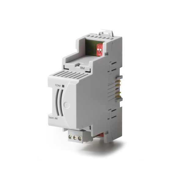
TX-I/O Power Supply, and Bus Connection Module ............................. 6
Document No. 553-632
February 2, 2007
Siemens Building Technologies, Inc.
Advertisement
Table of Contents

Related Manuals for Siemens TX-I/O


Summary of Contents for Siemens TX-I/O
-
Page 1: Table Of Contents
0-10 Vdc Sensors ....................10 2-Wire and 3-Wire Active Sensors............... 11 Analog Output Wiring Examples ................... 11 P1 Bus Interface Module, TX-I/O Power Supply, and Bus Connection Module..12 Power and Communication Connections............. 12 Extending Communication ................12 LED Indicators...................... 13 I/O Module LED States and Flash Patterns .............. -
Page 2: Common Ground Requirement
MEC Service Box Grounding Modification The MEC service box has a floating neutral system, which must be connected to the building approved earth ground for use with TX-I/O components, as follows: MEC Service Box Common Grounding Siemens Building Technologies, Inc... -
Page 3: Symbols
Symbols Symbols TX-I/O modules use the following set of symbols (also see LED Indicators and LED Symbol Chart in this document). ⊥ System neutral (‘N’ on MEC Service Box) Earth Ground (‘E’ on MEC Service Box) Configurable point Output (arrow pointing OUT from center of... -
Page 4: I/O Module Assembly
TX-I/O Quick Start I/O Module Assembly Siemens Building Technologies, Inc... -
Page 5: Separating A Module From Its Terminal Base
(‘parked’), but all wiring connections are now floating. To remove a module – Squeeze module sides above the release catch (18) and pull up to remove the I/O module from the terminal base. Siemens Building Technologies, Inc... -
Page 6: I/O Module Part Numbers, Features, And Point Types
4-20 mA 0-10 Vdc 4-20 mA ON/OFF Pulse ON Part Numbers and NEC Class – P1 Bus Interface Module, TX-I/O Power Supply, and Bus Connection Module Module Part Number and NEC Class Class 2 (Output) and Class 1 Class 2... -
Page 7: Supply Terminal Connections
For additional wiring and CE compliance information, see the APOGEE Wiring Guidelines for Field Panels and Equipment Controllers (125-3002). The following Installation Instructions are also available online: TX-I/O P1 Bus Interface Module (553-140), TX-I/O I/O Module (553-141), and TX-I/O Power Supply and Bus Connection Module (553-142). -
Page 8: Digital Input Wiring Examples
TX-I/O Quick Start Digital Input Wiring Examples Latched or Pulsed Accumulator (NO and NC) Status contact (N/O) DI Module (TXM1.8D or TXM1.16D) Status contact (N/C) Pulsed accumulator (N/O) Pulsed accumulator (N/C) Electronic switch (rated for 30 V) Universal Module (TXM1.8U or TXM1.8U-ML) and Super Universal Module (TXM1.8X or... -
Page 9: Digital Output Wiring Examples
Latched Contact (NO and NC) Switched load (N/O contact) Switched load (N/C contact) Digital Output Module (TXM1.6R or TXM1.6R-M) Pulsed Contact (NO and NC) Pulse-driven device (for example, a stepping switch) Power contactor, self-latching Digital Output Module (TXM1.6R or TXM1.6R-M) Siemens Building Technologies, Inc... -
Page 10: Analog Input Wiring Examples
TX-I/O Quick Start Analog Input Wiring Examples Temperature and Resistance Sensors Ni 1000 LS temperature sensor Pt 1000 385 and Pt 1000 375 temperature sensors Resistance-type sensor Universal Module (TXM1.8U or TXM1.8UML) and Super Universal Module (TXM1.8X or TXM1.8X-ML) 0-10 Vdc Sensors... -
Page 11: 2-Wire And 3-Wire Active Sensors
Y2-Y4 General powered device with control, 0-10 Vdc (or 4-20 mA, Super Universal, points 5-8 only) 24 Vac internal 24 Vdc internal 24 Vac or 24 Vdc external Universal Module (TXM1.8U or TXM1.8UML) and Super Universal Module (TXM1.8X or TXM1.8X-ML) Siemens Building Technologies, Inc... -
Page 12: P1 Bus Interface Module, Tx-I/O Power Supply, And Bus Connection Module
If an installation requires more than one DIN rail, connect the Communication Supply (CS) and Communication Data (CD) terminals from the P1 BIM to the same terminals on the first device of every additional DIN rail (a TX-I/O Power Supply or Bus Connection Module). TX-I/O Power Supplies and Bus Connection Modules include a second set of CS and CD contacts to simplify connection of additional DIN rails. -
Page 13: Led Indicators
P1 Bus Interface Module, TX-I/O Power Supply, and Bus Connection Module 24 Vac In 24 Vac In Common Common + 24 Vdc + 24 Vdc Data Data CS CD CS CD CS CD CS CD Data Data + 24 Vdc... -
Page 14: I/O Module Led States And Flash Patterns
TX-I/O Quick Start I/O Module LED States and Flash Patterns Module status LED – shows the module status as a whole (as opposed to the I/O points). Also used for diagnostics. Override status LEDs – when lit, these indicate that local override is active. -
Page 15: Lcd Symbol Chart
LCD Symbol Chart LCD Symbol Chart The Configured Signal Type is displayed with either a Signal Value that matches the signal type, or any one of the Errors, Reminders indicators. Examples: V A Ni Siemens Building Technologies, Inc... -
Page 16: Inserting The Address Keys
TX-I/O Quick Start Inserting the Address Keys The TX-I/O address keys must be inserted, seated, and closed correctly in order to function. Remove the address key from the strip, and then insert as shown. TX-I/O Start Up See the TX-I/O Getting Started Guide (553-636) for start-up procedures once the TX-I/O modules are installed, addressed, and wired.