Grizzly G1026 Owner's Manual
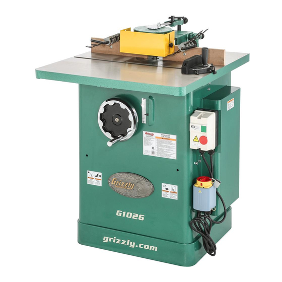
3 hp heavy-duty shaper
Hide thumbs
Also See for G1026:
- User manual (1 page) ,
- Parts list (10 pages) ,
- Instruction manual (56 pages)
Table of Contents
Advertisement
Quick Links
MODEL G1026
3 HP HEAVY-DUTY SHAPER
OWNER'S MANUAL
(For models manufactured since 10/13)
COPYRIGHT ©1991 BY GRIZZLY INDUSTRIAL, INC. REVISED APRIL, 2017 (BL)
WARNING: NO PORTION OF THIS MANUAL MAY BE REPRODUCED IN ANY SHAPE
OR FORM WITHOUT THE WRITTEN APPROVAL OF GRIZZLY INDUSTRIAL, INC.
#BL3325 PRINTED IN TAIWAN
V3.04.17
Advertisement
Table of Contents

Related Manuals for Grizzly G1026


Summary of Contents for Grizzly G1026
- Page 1 3 HP HEAVY-DUTY SHAPER OWNER'S MANUAL (For models manufactured since 10/13) COPYRIGHT ©1991 BY GRIZZLY INDUSTRIAL, INC. REVISED APRIL, 2017 (BL) WARNING: NO PORTION OF THIS MANUAL MAY BE REPRODUCED IN ANY SHAPE OR FORM WITHOUT THE WRITTEN APPROVAL OF GRIZZLY INDUSTRIAL, INC.
- Page 2 This manual provides critical safety instructions on the proper setup, operation, maintenance, and service of this machine/tool. Save this document, refer to it often, and use it to instruct other operators. Failure to read, understand and follow the instructions in this manual may result in fire or serious personal injury—including amputation, electrocution, or death.
-
Page 3: Table Of Contents
Table of Contents INTRODUCTION ..........2 Safety Guard Adjustment ......31 Contact Info............ 2 Straight Shaping .......... 32 Manual Accuracy ........... 2 Shaping Small Stock ........34 Identification ........... 3 Rub Collars ..........34 Controls & Components ......... 4 Irregular Shaping ......... 35 Machine Data Sheet ........ -
Page 4: Introduction
ID label (see below). This information is required for us to provide proper tech support, and it helps us determine if updated documenta- tion is available for your machine. Manufacture Date Serial Number Model G1026 (Mfd. Since 10/13) -
Page 5: Identification
Be sure keyed washer is directly under spindle nut and spindle nut is tight d) Feed workpiece AGAINST rotation of cutter. e) Keep fingers away from revolving cutter–use fixtures when necessary. f) Do not use awkward hand positions. Model G1026 (Mfd. Since 10/13) -
Page 6: Controls & Components
One turn moves each fence approximately " (.078"). Starting Pin (not shown): Supports workpiece during beginning of freehand cuts until workpiece contacts rub collar (refer to Page 35). Model G1026 (Mfd. Since 10/13) -
Page 7: Machine Data Sheet
MACHINE DATA SHEET Customer Service #: (570) 546-9663 · To Order Call: (800) 523-4777 · Fax #: (800) 438-5901 MODEL G1026 3 HP SHAPER Product Dimensions: Weight................................345 lbs. Width (side-to-side) x Depth (front-to-back) x Height............... 30 x 30-1/2 x 39-1/2 in. - Page 8 The information contained herein is deemed accurate as of 4/24/2017 and represents our most recent product specifications. Model G1026 PAGE 2 OF 2 Due to our ongoing improvement efforts, this information may not accurately describe items previously purchased. Model G1026 (Mfd. Since 10/13)
-
Page 9: Section 1: Safety
Everyday ery. Never operate under the influence of drugs or eyeglasses are NOT approved safety glasses. alcohol, when tired, or when distracted. Model G1026 (Mfd. Since 10/13) - Page 10 EXPERIENCING DIFFICULTIES. If at any time debris. Make sure they are properly installed, you experience difficulties performing the intend- undamaged, and working correctly BEFORE ed operation, stop using the machine! Contact our operating machine. Technical Support at (570) 546-9663. Model G1026 (Mfd. Since 10/13)
-
Page 11: Additional Safety For Shapers
“ring” type guard. To reduce kickback make shaping cuts with cutter on underside of risk, always use starting pin or pivot board when workpiece to reduce operator exposure to cutter. starting the cut. NEVER start shaping at a corner! Model G1026 (Mfd. Since 10/13) -
Page 12: Section 2: Power Supply
To reduce the risk of these hazards, avoid over- loading the machine during operation and make sure it is connected to a power supply circuit that meets the specified circuit requirements. -10- Model G1026 (Mfd. Since 10/13) - Page 13 Minimum Gauge Size ......14 AWG all local codes and ordinances. Maximum Length (Shorter is Better)..50 ft. -11- Model G1026 (Mfd. Since 10/13)
-
Page 14: Section 3: Setup
IMPORTANT: Save all packaging materials until you are completely satisfied with the machine and have resolved any issues between Grizzly or the shipping agent. You MUST have the original pack- aging to file a freight claim. It is also extremely helpful if you need to return your machine later. -
Page 15: Hardware Recognition Chart
Hardware Recognition Chart USE THIS CHART TO MATCH UP HARDWARE DURING THE INVENTORY AND ASSEMBLY PROCESS. Flat Head Screw -13- Model G1026 (Mfd. Since 10/13) -
Page 16: Inventory
Shaft Mount Bracket w/Set Screw ....1 • Top Plastic Safety Guard ......1 • Front Steel Safety Guard ......1 • Padlock with Keys (Pre-Installed) ....Note: Refer to Page 38 for a detailed listing of spacers supplied. -14- Model G1026 (Mfd. Since 10/13) -
Page 17: Cleanup
Figure 6. T23692 Orange Power Degreaser. Repeat Steps 2–3 as necessary until clean, then coat all unpainted surfaces with a quality metal protectant to prevent rust. -15- Model G1026 (Mfd. Since 10/13) -
Page 18: Site Considerations
Only install in an Shadows, glare, or strobe effects that may distract access restricted location. or impede the operator must be eliminated. Minimum 30" " 30" = Electrical Connection Figure 7. Minimum working clearances. -16- Model G1026 (Mfd. Since 10/13) -
Page 19: Assembly
(if applicable). Most of your Model G1026 has been assembled at the factory, but some parts must be assembled or installed after delivery. To assemble the shaper:... - Page 20 11. Thread the handle into the handwheel, and mounted in the cabinet at that location. tighten the hex nut on the handle against the handwheel. Mag Switch Figure 12. Securing mag switch to cabinet. -18- Model G1026 (Mfd. Since 10/13)
-
Page 21: Spindle
(see Each of the three spindles that come with the Figure 15). You will feel the spindle seat Model G1026 is sized to work efficiently with dif- itself. ferent sized cutters and spacers. The spindles... -
Page 22: Table Inserts
Place a 17mm wrench on the drawbar nut (see Figure 17). The Model G1026 is supplied with three table inserts which give you four possible opening diameters in the shaper table surface. Use the smallest opening that a particular cutter will allow. -
Page 23: Extension Wing
Note: By raising or lowering the far end of the wing, you can locate the center of the wing flush with the shaper table. Figure 20. Adjusting to ensure flatness. Figure 19. Installing extension wing. Secure the center bolt. -21- Model G1026 (Mfd. Since 10/13) -
Page 24: Fence Assembly
Figure 24. Figure 22. Masking tape location for raising wing. 10. Following adjustments, tighten the hex bolts in the sequence they were installed. Figure 24. Attaching wooden fence assembly. -22- Model G1026 (Mfd. Since 10/13) -
Page 25: Safety Guard
Always use the included safety guard or Guard Extension some type of guard when performing shaping operations. Lock Knob Extension Main Knob Bracket Guard Bolt (1 of 2) Shaft Shaft Mount Set Screw Figure 25. Safety guard assembly. -23- Model G1026 (Mfd. Since 10/13) -
Page 26: Hold-Downs
Slide the long arm of the hold-down bars Note: Remove the hold-down assembly when through the holes in the cast iron fence brack- not in use. ets, as shown in Figure 27. Figure 27. Inserting hold-down bar into fence bracket. -24- Model G1026 (Mfd. Since 10/13) -
Page 27: Dust Collection
3" dust hose over the dust hood and secure in place with a hose clamp. We recommend NOT operating the Model G1026 without an adequate dust collection system. This machine creates substantial amounts of wood dust while operating. -
Page 28: Test Run
(see Troubleshooting, Page 44). Always discon- nect machine from power when investigating or correcting problems. If problems persist, call Tech Support for help. Congratulations! The Test Run is now complete. Continue to Operations section. -26- Model G1026 (Mfd. Since 10/13) -
Page 29: Section 4: Operations
Read books/magazines or get formal training before beginning any proj- ects. Regardless of the content in this sec- tion, Grizzly Industrial will not be held liable for accidents caused by lack of training. -27- Model G1026 (Mfd. Since 10/13) -
Page 30: Disabling & Locking Switch
On Figure 32. Minimum lock shaft requirements. the contrary, a workpiece supported on the bowed side will rock during a cut and could cause kickback or severe injury. -28- Model G1026 (Mfd. Since 10/13) -
Page 31: Changing Cutter Rotation
Changing Cutter Speed Changes Rotation The Model G1026 Shaper is equipped with a spe- cial high-speed V-belt. It is designed to withstand Always check the direction of the cutter rota- the vibration and sudden shock loads associated tion before any shaping operation. -
Page 32: Cutter Installation
Cutter Collar Figure 38. Spindle lock knob. Figure 36. Cutter and fasteners. Move the spindle up or down with the eleva- tion handwheel until the desired position is obtained. Lock the spindle into position. -30- Model G1026 (Mfd. Since 10/13) -
Page 33: Fence Adjustment
To reduce your risk of injury, read and follow the entire Owner's Manual carefully and do additional research on shop-made guards and safety jigs. -31- Model G1026 (Mfd. Since 10/13) -
Page 34: Straight Shaping
Adjust the infeed fence by turning the knurled adjustment knob until the workpiece contacts the cutter in the desired location. Use a test piece at least 24" long to deter- mine the best setting. -32- Model G1026 (Mfd. Since 10/13) - Page 35 Figure 44. Cut end grain first. Run a test piece through the shaper (see Figure 43). End View Outfeed Infeed Fence Fence Direction of Feed Figure 43. Partial feed fence adjustment. Turn the shaper OFF. -33- Model G1026 (Mfd. Since 10/13)
-
Page 36: Shaping Small Stock
We recommend using ball bearing collars and we carry an extensive line that is designed for use with Grizzly shapers. See our current catalog or website for listings. Always use hold-downs or featherboards when shaping small or narrow stock. These... -
Page 37: Irregular Shaping
Figure 49. ALWAYS FEED AGAINST THE ROTATION OF THE CUTTER. -35- Model G1026 (Mfd. Since 10/13) - Page 38 Figure 52. Use starting pin substitute when Figure 50. Inserting starting pin. needed. (Guard removed for clarity.) Use some type of hold-down fixture and guard when doing freehand work (see Figure 51). -36- Model G1026 (Mfd. Since 10/13)
-
Page 39: Pattern Work
The workpiece must be fixed securely to the jig. Workpiece Figure 53. Position of pattern on workpiece and bearing size determine depth of cut. -37- Model G1026 (Mfd. Since 10/13) -
Page 40: Section 5: Accessories
To reduce this risk, only install accessories anywhere on the spindle. Use them between cut- recommended for this machine by Grizzly. ters or stack them above the cutter to bear against the spindle nut. Every shaper owner needs a set NOTICE of these on-hand. - Page 41 ". Approximate shipping weight: 62 lbs. 1000 Lb. Capacity! Figure 57. D2057A Shop Fox Mobile Base. G4839—3" Dust Hood This dust hood connects the G1026 to any 3" dust Figure 60. D2271 Shop Fox Roller Table. collection hose. Attaches to blade guard.
- Page 42 " Radius C2017—Cove and Bead ⁄ " Bore, 2" Diameter, 1" Cutting Height, C2018—Cabinet Door Lip ⁄ " Radius ⁄ " Bore, 2" Diameter, 1" Cutting Height www.grizzly.com 1-800-523-4777 order online at or call -40- Model G1026 (Mfd. Since 10/13)
-
Page 43: Section 6: Maintenance
Developed by Boeing engineers for aircraft appli- Monthly Check cations—this is the best! • Check/lubricate spindle slide and leadscrew (see Page 42). • Check V-belt condition and tension (see Page 43). Annually • Replace V-belt. Figure 63. Boeshield® T-9 spray. -41- Model G1026 (Mfd. Since 10/13) -
Page 44: Lubrication
To reduce damage, place a pad underneath the housing. The casting Re-install the rear cover. will break if too much pressure is applied. -42- Model G1026 (Mfd. Since 10/13) -
Page 45: V-Belt Tension & Replacement
Do not remove the bolts completely. Figure 66. Location of motor mount hex bolts. — If the V-belt is cracked, excessively worn, or damaged, slide the motor to the right, then replace the V-belt. -43- Model G1026 (Mfd. Since 10/13) -
Page 46: Section 7: Service
7. Tighten mounting bolts; relocate/shim machine. 8. Motor fan rubbing on fan cover. 8. Fix/replace fan cover; replace loose/damaged fan. 9. Motor bearings at fault. 9. Test by rotating shaft; rotational grinding/loose shaft requires bearing replacement. -44- Model G1026 (Mfd. Since 10/13) - Page 47 1. Inconsistent feed speed. 1. Move smoothly or use a power feeder. the cut. 2. Inconsistent pressure against the fence and 2. Apply constant pressure. rub collar. 3. Fence not adjusted correctly. 3. Adjust fence. -45- Model G1026 (Mfd. Since 10/13)
-
Page 48: Table Insert Adjustment
Note: Notice that there is a barrel screw table top in all directions. underneath each of the Phillips screws (see Figure 68). Figure 68. Insert ring barrel screw. -46- Model G1026 (Mfd. Since 10/13) -
Page 49: Fence Board Alignment
Figure 71. Example of resurfacing fences on a their entire length. jointer. -47- Model G1026 (Mfd. Since 10/13) -
Page 50: Pulley Alignment
Using the straightedge as a guide, rotate the motor assembly until the motor pulley is par- allel with the spindle pulley, then re-tighten the four motor mount hex bolts and re-tighten the two motor mount hex bolts under the spindle cartridge. -48- Model G1026 (Mfd. Since 10/13) -
Page 51: Gib Adjustment
Replace the motor cover and rear cover before reconnecting the machine to power. -49- Model G1026 (Mfd. Since 10/13) - Page 52 Loosen the jam nuts on the gib adjustment set screws (see Figure 76). Adjustment Set Screws & Jam Nuts Figure 76. Location of set screws and jam nuts for adjusting gibs. -50- Model G1026 (Mfd. Since 10/13)
-
Page 53: Section 8: Wiring
EXPERIENCING DIFFICULTIES. If you are expe- the requirements at the beginning of this manual riencing difficulties understanding the information when connecting your machine to a power source. included in this section, contact our Technical Support at (570) 546-9663. -51- Model G1026 (Mfd. Since 10/13) -
Page 54: Wiring Diagram
Note: The wires from the power supply (except the green ground) are interchangeable; therefore colors are not specified. READ ELECTRICAL SAFETY -52- Model G1026 (Mfd. Since 10/13) ON PAGE 51! -
Page 55: Section 9: Parts
SECTION 9: PARTS We do our best to stock replacement parts when possible, but we cannot guarantee that all parts shown are available for purchase. Call (800) 523-4777 or visit www.grizzly.com/parts to check for availability. Stand & Table 23 21... - Page 56 FENCE MOUNT (LH) V2.12.95 P1026072 FLAT WASHER 5/16 P1026032 MAGNETIC SWITCH MOUNT BRACKET P1026073 HEX BOLT 5/16-18 X 3/4 P1026033 MAGNETIC SWITCH 3HP 1PH P1026505 COMPLETE FENCE ASSY 33-1 P1026033-1 CONTACTOR SDE MA-15 220V -54- Model G1026 (Mfd. Since 10/13)
-
Page 57: Motor & Handwheel
Motor & Handwheel 152-1 152-4 152-3 152-2 152-5 142 143 120A 115A 117 116 133A 156-1 102A 101A -55- Model G1026 (Mfd. Since 10/13) - Page 58 HEX NUT 5/16-18 133A P1026133A THRUST BEARING 51103 P1026158 HEX BOLT 5/16-18 X 3/4 P1026135 KEY 5 X 5 X 18 P1026159 TOP MOTOR SHIPPING BRACE P1026136 ELEVATION LEADSCREW 3/4 X 7-1/2 P1026160 FLAT WASHER 5/16 -56- Model G1026 (Mfd. Since 10/13)
-
Page 59: Spindle
Spindle 226B 226A -57- Model G1026 (Mfd. Since 10/13) - Page 60 1-1/4'' 1-1/2'' 1/4'' W1168 3/8'' W1170 1-1/2'' 1-1/2'' 1/2'' W1171 1-1/2'' 3/4'' W1172 W1173 1-1/2'' 1-1/4'' 1-3/4'' 1/4'' W1174 3/8'' W1175 1-1/4'' 1-3/4'' 1-1/4'' 1-3/4'' 1/2'' W1176 3/4'' W1177 1-1/4'' 1-3/4'' W1178 1-1/4'' 1-3/4'' -58- Model G1026 (Mfd. Since 10/13)
-
Page 61: Safety Guard
P1026317 FLAT WASHER 1/4 P1026306 LOCK KNOB BOLT P1026318 KNOB BOLT 1/4-20 X 1/2 P1026309 SHAFT P1026319 FRONT SAFETY GUARD (STEEL) P1026310 LOCK HANDLE P1026320 TOP SAFETY GUARD (PLASTIC) 313V2 P1026313V2 HEX NUT 1/4-20 -59- Model G1026 (Mfd. Since 10/13) -
Page 62: Fence
Fence REF PART # DESCRIPTION REF PART # DESCRIPTION P1026501 HOLD-DOWN BAR P1026503 HOLD-DOWN BRACKET P1026502 HOLD-DOWN P1026504 SET SCREW 5/16-18 X 3/8 -60- Model G1026 (Mfd. Since 10/13) -
Page 63: Miter Gauge
SET SCREW 10-24 X 5/8 P1026607 HEX NUT 10-24 P1026614 ROLL PIN 1.5 X 13 608A P1026608A SET SCREW 10-24 X 3/4 P1026615 MITER GAUGE HINGE PIN 609A P1026609A SET SCREW 10-24 X 1/4 -61- Model G1026 (Mfd. Since 10/13) -
Page 64: Labels & Cosmetics
Safety labels help reduce the risk of serious injury caused by machine hazards. If any label comes off or becomes unreadable, the owner of this machine MUST replace it in the original location before resuming operations. For replacements, contact (800) 523-4777 or www.grizzly.com. -62-... - Page 65 Would you recommend Grizzly Industrial to a friend? _____ Yes _____No Would you allow us to use your name as a reference for Grizzly customers in your area? Note: We never use names more than 3 times. _____ Yes _____No 10.
- Page 66 FOLD ALONG DOTTED LINE Place Stamp Here GRIZZLY INDUSTRIAL, INC. P.O. BOX 2069 BELLINGHAM, WA 98227-2069 FOLD ALONG DOTTED LINE Send a Grizzly Catalog to a friend: Name_______________________________ Street_______________________________ City______________State______Zip______ TAPE ALONG EDGES--PLEASE DO NOT STAPLE...
-
Page 67: Warranty & Returns
WARRANTY & RETURNS Grizzly Industrial, Inc. warrants every product it sells for a period of 1 year to the original purchaser from the date of purchase. This warranty does not apply to defects due directly or indirectly to misuse, abuse, negligence, accidents, repairs or alterations or lack of maintenance.