Viessmann Vitotrol 100 UTDB-RF2 Installation And Service Instructions Manual
Room temperature controller with digital time switch and wireless receiver for the vitodens 100-w
Hide thumbs
Also See for Vitotrol 100 UTDB-RF2:
- Installation and service instructions manual (16 pages)
Table of Contents
Advertisement
Advertisement
Table of Contents

Related Manuals for Viessmann Vitotrol 100 UTDB-RF2


Summary of Contents for Viessmann Vitotrol 100 UTDB-RF2
- Page 1 VIESMANN Installation and service instructions for contractors Vitotrol 100 Type UTDB-RF2 Room temperature controller with digital time switch and wireless receiver For the Vitodens 100-W For applicability, see the last page VITOTROL 100 Please keep safe. 5601 636 GB 12/2014...
- Page 2 ■ Statutory regulations for the protection of the envi- For replacements, use only original spare parts ronment supplied or approved by Viessmann. ■ Codes of Practice of the relevant trade associations All current safety regulations as defined by DIN, EN, Safety instructions for operating the system ■...
- Page 3 Safety instructions Safety instructions (cont.) If you smell flue gas Danger Flue gas can lead to life threatening poisoning. ■ Shut down the heating system. ■ Ventilate the installation site. ■ Close doors to living spaces to prevent flue gases from spreading. Flue systems and combustion air Ensure that flue systems are clear and cannot be sealed, for instance due to accumulation of conden-...
-
Page 4: Table Of Contents
Index Index Information Symbols ....................Preparing for installation Function ....................Installation location ................Installation sequence Mounting and connecting the wireless receiver ........Installing the wireless receiver ............■ Opening the control unit enclosure ............. ■ Connecting the wireless receiver ............■... -
Page 5: Symbols
Information Symbols Symbol Meaning Reference to other document containing further information Additional information, not safety relevant Step: The numbering corresponds to the se- quence of work. -
Page 6: Function
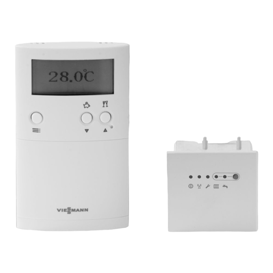
Preparing for installation Function The Vitotrol 100 type UTDB-RF2 maintains a constant room temperature by means of its integral room tem- perature sensor in conjunction with the wireless receiver. During the set periods, there is a changeover between operation with standard "Comfort" room temperature and operation with reduced "Eco"... -
Page 7: Mounting And Connecting The Wireless Receiver
Installation sequence Mounting and connecting the wireless receiver Installing the wireless receiver ë Fig.1 1. Remove the cover. 4. Seal the aperture with a grommet. 2. Remove the round label from the aperture. 5. Install the wireless receiver. 3. Route the lead through the aperture. Opening the control unit enclosure Please note Electronic assemblies can be damaged by elec-... -
Page 8: Connecting The Wireless Receiver
Installation sequence Mounting and connecting the wireless receiver (cont.) Fig.2 Connecting the wireless receiver PUMP L N 1 L N Fig.3 1. Insert the wireless receiver cable into the control 2. Close the control unit enclosure and pivot up the unit enclosure and push the plug into "X7". -
Page 9: Installing The Vitotrol 100
Installation sequence Installing the Vitotrol 100 Opening the Vitotrol 100 Fig.4 Fitting the wall mounting base Always check reception prior to fitting to the wall (see Power is supplied by batteries (see chapter "Specifica- page 11). tion"). -
Page 10: Assembling The Vitotrol 100
Installation sequence Installing the Vitotrol 100 (cont.) Fig.5 Assembling the Vitotrol 100 Fig.6... -
Page 11: Commissioning The Vitotrol 100
Commissioning Commissioning the Vitotrol 100 1. Open the hinged flap. 2. Use a pointed object to press "reset". 3. Select language with / . 4. Confirm with OK. 5. Set current date and time with / . 6. Confirm with OK. Fig.7 Commissioning the wireless receiver Several Vitotrol 100 and the wireless receiver can be... -
Page 12: Testing Switching Outputs
Commissioning Commissioning the wireless receiver (cont.) Testing switching outputs 1. Press on the wireless receiver (see diagram on 2. Terminate the function: page 11) repeatedly until the required condition is Press reached (see following table). Function Central heating and DHW heating OFF Central heating OFF, DHW heating enabled Central heating enabled, DHW heating OFF Central heating and DHW heating enabled... -
Page 13: Changing The Address Code
Service settings Changing the address code Change the address code if the wireless connection between the Vitotrol 100 and the wireless receiver fails. 1. Hold down on the wireless receiver (see dia- gram on page 11) for approx. 10 s until LED flashes. -
Page 14: Specification
Specification Specification Vitotrol 100 Rated voltage – 2 batteries LR 6/AA Ambient temperature Operation 0 to 40 °C ■ Storage and transport 25 to +60 °C − ■ IP rating IP 20 to EN 60529 Safety category II to EN 60730-1 Radio frequency 868 MHz Wireless receiver... -
Page 15: Declaration Of Conformity
Declaration of conformity Declaration of conformity We, Viessmann Werke GmbH & Co KG, D-35107 Allendorf, declare as sole responsible body that the product Vitotrol 100, type UTDB-RF complies with the following standards: EN 60730-1 EN 55014-1 EN 60730-2-9 EN 55014-2 EN 60335-1 EN 301 489–1... - Page 16 Applicability Serial No.: 7454522 7454523 7537234 Fig.9 Viessmann Werke GmbH&Co KG Viessmann Limited D-35107 Allendorf Hortonwood 30, Telford Telephone: +49 6452 70-0 Shropshire, TF1 7YP, GB Fax: +49 6452 70-2780 Telephone: +44 1952 675000 www.viessmann.com Fax: +44 1952 675040 E-mail: info-uk@viessmann.com...