Table of Contents

Related Manuals for Viessmann VITOTROL 100 UTA-RF


Summary of Contents for Viessmann VITOTROL 100 UTA-RF
-
Page 1: Installation Instructions
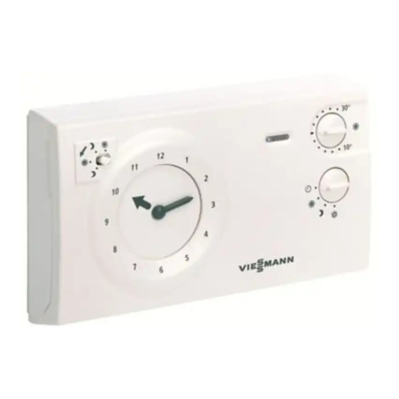
VIESMANN Installation instructions for contractors Vitotrol 100 Type UTA-RF Room thermostat with analog time switch and wireless receiver for the Vitodens 100-W, type WB1B Part no: 7296 064 VITOTROL 100 Dispose after installation. 5355 246 2/2008... -
Page 2: Safety Instructions
Safety instructions Please follow these safety instructions closely to prevent accidents and material losses. Safety instructions explained & the Code of Practice of relevant trade associations, Please note & all current safety regulations as This symbol warns against the defined by DIN, EN, DVGW, TRGI, risk of material losses and TRF, VDE and all locally applicable environmental pollution. -
Page 3: Table Of Contents
Index Preparing for installation Before installation..................& Information regarding use ................ & Installation location .................. Installation sequence Installing the wireless receiver ..............& Opening the control unit casing ..............& Installing the wireless receiver ..............Fitting the clock thermostat ................. Inserting batteries .................. -
Page 4: Before Installation
Before installation Information regarding use Combine only Vitotrol and wireless receivers from the same pack, as only these are matched to each other. Installation location Clock thermostat Wireless receiver & In the main living room on an inter- & Built into the boiler. nal wall opposite radiators. -
Page 5: Installing The Wireless Receiver
Installing the wireless receiver Opening the control unit casing Please note Electronic modules can be damaged by electrostatic dis- charges. Touch earthed objects, such as heating or water pipes, to dis- charge static loads. -
Page 6: Installing The Wireless Receiver
Installing the wireless receiver (cont.) Installing the wireless receiver 1. Remove the cover from the control 3. Insert the wireless receiver into the unit support. control unit support. 2. Push the wireless receiver cable through the opening in the control unit support. - Page 7 Installing the wireless receiver (cont.) 4. Insert the wireless receiver cable 5. Close the control unit casing and into the control unit casing and flip up the control unit. push the plug onto terminal "X7". The plug must click home.
-
Page 8: Fitting The Clock Thermostat
Fitting the clock thermostat... -
Page 9: Inserting Batteries
Inserting batteries 1. Insert batteries into the battery compartment (observe correct polarity). -
Page 10: Adjusting The Room Thermostat
Adjusting the room thermostat A Controller for electronic feedback B Temperature matching controller Electronic feedback (hysteresis setting) The switching hysteresis is influenced by the electronic feedback. At the factory, the Vitotrol 100 is set to standard mode. Only change this setting if the control unit must be adapted to the heating system. -
Page 11: Dhw Heating
Adjusting the room thermostat (cont.) Temperature matching A matching of temperatures may be required to adapt the controller to local con- ditions, e.g. when installing it on a cold concrete wall. & Regulated temperature too high: Turn the controller towards "–" to adjust the temperature &... - Page 12 Adjusting the room thermostat (cont.) Rotary selector position DHW heating function DHW heating in accordance with the selected time program DHW heating "permanently ON", inde- pendent of the selected time program DHW heating "permanently OFF", in- dependent of the selected time pro- gram...
-
Page 13: Wireless Receiver Commissioning
Wireless receiver commissioning Several clock thermostats and wireless receivers can be installed in a single building. Both are matched up to each other in the factory. If several clock ther- mostats are fitted with the wireless receiver in a single building complex, never swap the respective clock thermostat and wireless receiver, as each clock ther- mostat can only communicate with the respectively allocated wireless receiver. - Page 14 Wireless receiver commissioning (cont.) Testing switching outputs 1. Press C at the wireless receiver 3. Terminate the function: Press C at the wireless receiver (see diagram on page 13) The LED "r" indicates the switch- ing state: automatic if the switching output is LED ON: Output "ON"...
-
Page 15: Specification
Specification Clock thermostat Rated voltage 3 V– 2 batteries LR 6 Switching hysteresis 0.4 to 1.5 K Power consumption Protection class Protection IP 20 Ambient temperature & during operation 5 to 40 °C & during storage and transport -20 to 40 °C Function Type 1B to EN 60730-1 Wireless receiver... - Page 16 Viessmann Werke GmbH&Co KG Viessmann Limited D-35107 Allendorf Hortonwood 30, Telford Telephone: +49 6452 70-0 Shropshire, TF1 7YP, GB Fax: +49 6452 70-2780 Telephone: +44 1952 675000 www.viessmann.com Fax: +44 1952 675040 E-mail: info-uk@viessmann.com...