Viessmann Vitotrol 100 Installation Instructions For Contractors
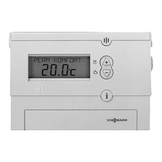
Clock thermostat with digital time switch and wireless receiver
Hide thumbs
Also See for Vitotrol 100:
- Operating instructions manual (36 pages) ,
- Operating instructions for the system user (36 pages) ,
- Installation instructions for contractors (20 pages)

Related Manuals for Viessmann Vitotrol 100


Summary of Contents for Viessmann Vitotrol 100
- Page 1 VIESMANN Installation instructions for contractors Vitotrol 100 Type UTD-RF Clock thermostat with digital time switch and wireless receiver Part no: 7160 432 VITOTROL 100 Dispose after installation. 5592 960 GB 12/2007...
- Page 2 Safety instructions Please follow these safety instructions closely to prevent accidents and material losses. Safety instructions explained the Code of Practice of relevant trade associations, all current safety regulations as Details identified by the word "Note" defined by DIN, EN, DVGW, TRGI, contain additional information.
-
Page 3: Table Of Contents
Index Preparing for installation Before the installation ................. Function ....................Installation location .................. Installation sequence Fitting the clock thermostat ................. Installing the wireless receiver ..............Electrical connections at the control unit ............. Connection at the control unit with plug lH ..........Connection at the control unit with plug gH .......... -
Page 4: Before The Installation
Before the installation Function The Vitotrol 100 UTD-RF controls the room temperature by starting and stopping, for example a heating circuit pump, via the wireless receiver. Installation location Clock thermostat Wireless receiver In the main living room on an inter- Immediately by the component to be nal wall opposite radiators. -
Page 5: Fitting The Clock Thermostat
Fitting the clock thermostat Power is supplied by batteries (see chapter "Specification"). Always check reception prior to fitting to the wall (see page 11). Wall mounting Alternatively, the clock thermostat can also be positioned as freestanding unit with the plinth supplied. Installing the wireless receiver Always check reception prior to installation (see page 11). -
Page 6: Electrical Connections At The Control Unit
Installing the wireless receiver (cont.) Electrical connections at the control unit Connection at the control unit with plug lH Recommended connecting cable Cable with a cross-section of 1.5 mm² for 230 V~... -
Page 7: Connection At The Control Unit With Plug Gh
Electrical connections at the control unit (cont.) Insert the jumper between terminals 1 and 4 in the wireless receiver. Leave terminal 3 in the wireless recei- ver free. A Terminals inside the wireless receiver Connection at the control unit with plug gH Recommended connecting cable Cable with a cross-section of 1.5 mm²... -
Page 8: Connection At The Control Unit With Plug A-D
Electrical connections at the control unit (cont.) Connection at the control unit with plug a-D Recommended connecting cable Cable with a cross-section of 1.5 mm² for 230 V~ 1. Remove jumper B between term- inals 1 and 3 in plug a-D. 2. -
Page 9: General Connection
Electrical connections at the control unit (cont.) General connection A Terminals inside the wireless B Components to be switched, e.g. receiver heating circuit pump Recommended connecting cable Cable with a cross-section of 1.5 mm² for 230 V~... -
Page 10: Commissioning The Clock Thermostat
Commissioning the clock thermostat 1. Open the battery compartment. to confirm. 2. Remove the paper strip. for time and date. Press the following keys: to confirm. 3. RES Reset button for language. -
Page 11: Wireless Receiver Commissioning
Wireless receiver commissioning Several clock thermostats and the wireless receiver can be installed in a single building. Both are matched up to each other in the factory. If several clock ther- mostats are fitted with the wireless receiver in a single building complex, never swap the respective clock thermostats and wireless receiver, as each clock thermostat can only communicate with the respectively allocated wireless recei- ver. -
Page 12: Testing The Zero Volt Contact (Switching Output)
Testing the zero volt contact (switching output) 1. Press "C1" at the wireless receiver 2. Terminate the function: (see diagram on page 11) Press "C1" at the wireless receiver. The LED below "C1" indicates the switching state: automatic, if the switching output is LED ON: Output "ON"... -
Page 13: Specification
Specification Clock thermostat Rated voltage 2 batteries LR 6 Ambient temperature during operation 0 to 50 °C during storage and transport -10 to 60 °C Protection IP 20 to EN 60529; Shut-off function RS type 1B Wireless receiver Reception frequency 868 MHz Rated voltage 230 V~ +/ 10% 50 Hz... - Page 16 Viessmann Werke GmbH&Co KG Viessmann Limited D-35107 Allendorf Hortonwood 30, Telford Telephone: +49 6452 70-0 Shropshire, TF1 7YP, GB Fax: +49 6452 70-2780 Telephone: +44 1952 675000 www.viessmann.com Fax: +44 1952 675040 E-mail: info-uk@viessmann.com...