Advertisement
Quick Links
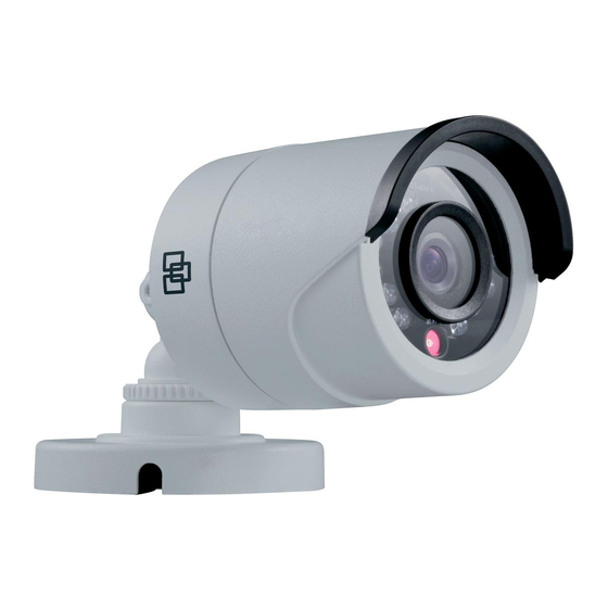
TruVision High Definition TVI Bullet Camera
Installation Guide
Product overview
This is the Installation Guide for TruVision High Definition TVI
Bullet Camera TVB-2401/TVB-4401 and TVB-2403/TVB-4403.
This guide describes a standard installation.
Package contents:
Camera with power and
video output cables
Template
•
WEEE and Battery
Disposal
Camera description
TVB-2401/TVB-4401
3
4
2
5
6
1.
TVI video output cable (grey)
2.
Power cable
3.
Mounting base output
© 2015 United Technologies Corporation. All rights reserved.
Interlogix is part of UTC Building & Industrial Systems, a unit of United Technologies Corporation. All rights reserved.
3 screws and 3 anchors
for wall or ceiling
installation
Installation Guide
CD
1
4.
Sun shield
5.
Lens
6.
IR LED
TVB-2403/TVB-4403
5
6
7
8
1.
WDR/CVBS switch cable
2.
Power cable
3.
TVI video output cable (grey)
4.
CVBS video output cable
(black)
Note:
Please check the camera output settings before setting up a
system. The TVI video output can be only connected to a DVR
with TVI signal input. The CVBS output supports the standard
monitor, test monitor, encoder and DVR.
For TVB-2403/TVB-4403, you can connect the white and black
line ends of the WDR switch cable to enable the Wide Dynamic
Range (WDR) function. The WDR function is disabled by
default. If WDR is enabled, the CVBS output will be blocked
out, and only TVI output is available.
Installation
To install the camera on a ceiling:
1.
Using the template, place it level against the mounting
surface and mark the position of the mounting holes.
Drill Template
2.
Following all local codes, drill and prepare the mounting
holes.
3.
Securely fasten the mount to the mounting surface with
the screws.
P/N 1072936-EN • REV A • ISS 26MAR15
1
2
3
4
5.
Mounting base
6.
Sun shield
7.
Lens
8.
IR LED
Advertisement

Related Manuals for Interlogix TruVision TVB-2401


Summary of Contents for Interlogix TruVision TVB-2401
-
Page 1: Installation Guide
Securely fasten the mount to the mounting surface with the screws. © 2015 United Technologies Corporation. All rights reserved. P/N 1072936-EN • REV A • ISS 26MAR15 Interlogix is part of UTC Building & Industrial Systems, a unit of United Technologies Corporation. All rights reserved. -
Page 2: Specifications
Regulatory information Programming on TVI output is available for TVB-2403/TVB- 4403 only. Manufacturer Interlogix. Once the camera hardware has been installed, you can 2955 Red Hill Avenue, Costa Mesa, CA 92626 configure the camera settings on the TVI DVR. 5923, USA... -
Page 3: Contact Information
For more information see: www.recyclethis.info. © 2015 United Technologies Corporation. Copyright Interlogix is part of UTC Building & Industrial Systems, a unit of United Technologies Corporation. All rights reserved. The trade names used in this document may be...