Interlogix TruVision TVB-2402 Installation Manuals
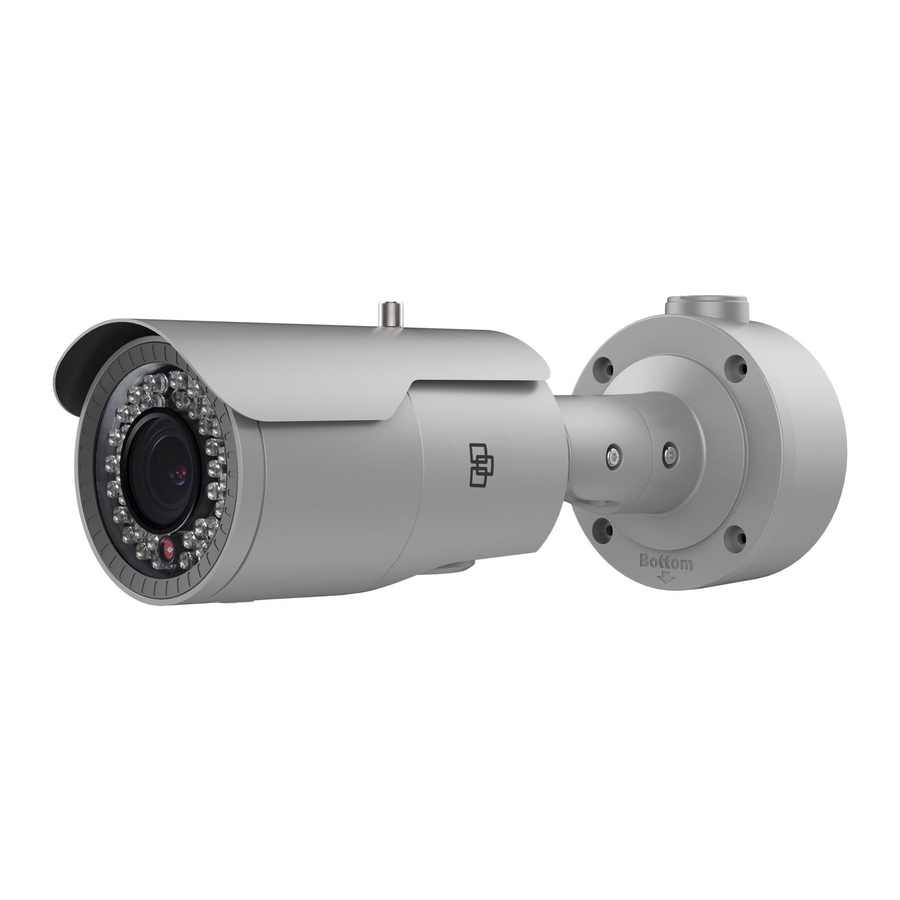
High definition tvi bullet camera
Hide thumbs
Also See for TruVision TVB-2402:
- Configuration manual (10 pages) ,
- Installation manual (20 pages) ,
- Installation manual (28 pages)

Related Manuals for Interlogix TruVision TVB-2402


Summary of Contents for Interlogix TruVision TVB-2402
- Page 1 TruVision High Definition TVI Bullet Camera Installation Guide TVB-2402/TVB-4402 TVB-2404/TVB-4404 TVB-2405/TVB-4405 P/N 1073164-EN • REV A • ISS 31MAR16...
-
Page 3: Table Of Contents
Contents Product overview 2 Camera description 4 Installation 7 Built-in heater in the TVB-2405/4405 camera 11 Program 11 Menu trees 17 Specifications 19 Legal and regulatory information 21 Installation Guide... -
Page 4: Product Overview
Product overview This is the TruVision High Definition TVI Bullet Camera Installation Guide for models TVB- 2402/TVB-4402, TVB-2404/TVB-4404 and TVB- 2405/TVB-4405. This guide describes a standard installation. Package contents Camera with power 4 screws and 4 and video output anchors for wall or cables ceiling installation... - Page 5 Template Hex wrench Drill Template Hole A: for cables routed through the wall Screw hole 1: for integrative bracket Screw hole 2: for conduit back box • Installation guide • WEEE disposal sheet • BNC monitor output cable Installation Guide...
-
Page 6: Camera Description
Camera description CVBS output Sun shield (black) Lens TVI output (grey) Mounting bracket Power cable Back box Camera body Note: Please check the camera output settings before setting up a system. The TVI video output can be only connected to a DVR with a TVI signal input. The CVBS output supports a standard CVBS monitor (or test monitor), an encoder or a DVR. - Page 7 For 720P VF bullet cameras, TVB-2402 / TVB-4402, the CVBS and TVI output can not be used at the same time. Use the built-in switch to select the camera video output. For 1080P VF bullet cameras, such as TVB- 2404/TVB-4404 and TVB-2405/TVB-4405, the built- in switch is used to enable/disable the WDR feature.
- Page 8 Figure 2: TVB-2404 /TVB-4404 Focus Zoom Menu button Switch (Up= CVBS/ Down = WDR) BNC output Figure 3: TVB-2405 /TVB-4405 BNC output Menu button Switch (Up= CVBS/ Down = WDR) Installation Guide...
-
Page 9: Installation
Installation To install the camera: Using the template, place it level against the mounting surface and mark the position of the mounting holes. Drill Template Hole A: for cables routed through the wall Screw hole 1: for integrative bracket Screw hole 2: for conduit back box Following all local safety regulations, drill and prepare the mounting holes. - Page 10 Route the cables to the cable hole and connect the corresponding cables. Using a 75-ohm coaxial video cable, connect the camera TVI video output to a TVI DVR, and connect a 12 VDC or 24 VAC power supply to the power cable.
- Page 11 Loosen the three screws on the mounting bracket and adjust the camera angle according to the figure below to the optimum position. Tighten the screws after completing the adjustment. Installation Guide...
- Page 12 360° 90° 360° Zoom and focus adjustment Manually adjust the zoom and focus on TVB-2402/TVB-4402 and TVB-2404/TVB- 4404. TVB-2405/TVB-4405 has a motorized lens. Please adjust its zoom and focus by using Installation Guide...
-
Page 13: Built-In Heater In The Tvb-2405/4405 Camera
the zoom and focus buttons on the PTZ panel of a connected recorder or controllor. Built-in heater in the TVB- 2405/4405 camera The TVB-2405/4405 camera has a built-in heater that works within the temperature range of -40 and +60 °C (-40 to +140 °F). The heater only works at 24 VAC. - Page 14 The camera has a built-in OSD button and supports UtC (Up-to-Coax) control over both CVBS and TVI outputs. Using the buttons Please press the Menu button to call up the OSD menu and select an OSD item. Press the button up/down to move the cursor up or down to an OSD item.
- Page 15 Figure 4: TVI cable connection Access the PTZ menu of the connected DVR, set TruVision-Coax protocol and use the PTZ control panel to configure the camera. Iris+ Click to access to the camera OSD menu and select an OSD item. Click the directional buttons UP or DOWN to move the cursor up or down to an OSD item.
- Page 16 Using a CVBS output A TVS-C200 (purchase separately) can be used to program the camera over its CVBS output, not the TVI video output. Connect a monitor and the TVS-C200 controller (if required) as shown below. Figure 5: CBSC cable connections Press the button of the TVS-C200 for a few seconds until you see the OSD menu display on the...
- Page 17 Use the directional buttons to move cursor and adjust value. For more details, refer to the TVS-C200 user manual. TVB-2402/TVB-4402 camera The camera has CVBS and TVI dual video outputs. Set the built-in switch to CVBS to view the program on a standard monitor.
- Page 18 When the programing is finished, you can change the switch setting to to enable the WDR feature. In such case, the CVBS output will be disabled. If the switch is set to CVBS, the WDR feature is disabled and the camera has both CVBS and TVI output available.
-
Page 19: Menu Trees
Menu trees Figure 6: TVB-2402/TVB-4402 menu tree Installation Guide... - Page 20 Figure 7: TVB-2404/TVB-4404 and TVB- 2405/TVB-4405 menu tree Installation Guide...
-
Page 21: Specifications
Specifications Power supply 12 VDC / 24 VAC Current TVB-2402 / TVB-4402: 12 VDC: Max. 333 mA 24 VAC: Max. 250 mA TVB-2404/TVB-4404: 12 VDC: Max. 420 mA 24 VAC: Max. 250 mA TVB-2405/TVB-4405: 12 VDC: Max. 1A 24 VAC: Max. 500 mA TVB-2402/TVB-4402: Power consumption... - Page 22 Weight (net) TVB-2402/TVB-4402: 860 g / 1.89 lb. (without back box) 1075 g / 2.36 lb. (with back box) TVB-2404/TVB-4404: 860 g / 1.89 lb. (without back box) 1075 g / 2.36 lb. (with back box) TVB-2405/TVB-4405: 880 g / 1.94 lb. (without back box) 1095 g / 2.41 lb.
-
Page 23: Legal And Regulatory Information
Legal and regulatory information Copyright: © 2016 United Technologies Corporation. All rights reserved. Interlogix is part of UTC Climate, Controls & Security, a unit of United Technologies Corporation. Trademarks and patents: Trade names used in this document may be trademarks or registered trademarks of the manufacturers or vendors of the respective products. - Page 24 For proper recycling, return this product to your local supplier upon the purchase of equivalent new equipment, or dispose of it at designated collection points. For more information see: www.recyclethis.info. Contact information: For contact information, see www.interlogix.com or www.utcfssecurityproducts.eu Installation Guide...