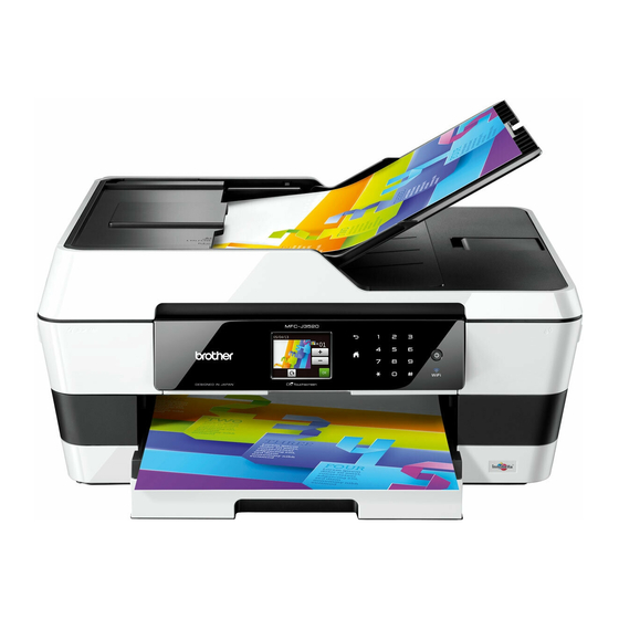
Brother MFC-J3520 Service Manual
Inkjet mfc
Hide thumbs
Also See for MFC-J3520:
- User manual (220 pages) ,
- Quick setup manual (45 pages) ,
- Safety manual (21 pages)
Table of Contents
Advertisement
Quick Links
Download this manual
See also:
User Manual
Advertisement
Table of Contents
Troubleshooting

Related Manuals for Brother MFC-J3520


Summary of Contents for Brother MFC-J3520
- Page 1 Brother Inkjet MFC SERVICE MANUAL MODELS: MFC-J3520/J3720 MFC-J6520DW/J6720DW MFC-J6920DW/J6925DW Read this manual thoroughly before maintenance work. Keep this manual in a convenient place for quick and easy reference at all times. June 2013 SM-FAX145 8CAT* Confidential...
- Page 2 Each company whose software title is mentioned in this manual has a Software License Agreement specific to its proprietary programs. Any trade names and product names of companies appearing on Brother products, related documents and any other materials are all trademarks or registered trademarks of those respective companies.
- Page 3 The table below shows the functional comparison between the models covered by this manual. MFC-J3520 MFC-J3720 MFC-J6520DW MFC-J6720DW MFC- J6920DW/ J6925DW 2.7 inch 2.7 inch 2.7 inch 2.7 inch 3.7 inch Duplex scan Main PCB B57U184 B57U184 B57U184...
-
Page 4: Table Of Contents
TABLE OF CONTENTS REGULATION ........................ix SAFETY INFORMATION ..................... xiv CHAPTER 1 SPECIFICATIONS ..................1-1 GENERAL ........................1-1 General........................1-1 Media Specification ....................1-1 Paper Handling...................... 1-2 LCD Panel ......................1-2 Memory........................1-2 Interface......................... 1-2 Others........................1-3 FAX..........................1-4 PRINTER ........................1-4 COPY.......................... - Page 5 Cross-section Drawings..................2-3 2.1.1 Document scanning ..................2-3 2.1.2 Printer part ....................2-4 Document Feeding Path/Recording Paper Feeding Path ........2-5 2.2.1 Document Feeding Path ................2-5 2.2.2 Recording Paper Feeding Path..............2-5 Parts Names and Functions .................. 2-6 Block Diagram ....................... 2-8 Components ......................
- Page 6 4.7.3 Document jam ..................... 2-75 4.7.4 Wrinkles on documents................2-77 4.7.5 Document size not correctly detected ............2-77 Scanned-image Problems ................... 2-78 4.8.1 Defective images..................2-78 4.8.2 Troubleshooting from image defect............. 2-78 Fax Problems ...................... 2-83 4.9.1 No faxes can be sent .................. 2-83 4.9.2 No faxes can be received................
- Page 7 ADF Unit, Document Scanner Unit and ADF Hinge ..........3-48 ADF Document Support ..................3-52 9.10 ADF Cover ASSY and ADF Cover Side Cover............ 3-53 9.11 ADF Front Cover ....................3-54 9.12 ADF Side Cover L....................3-54 9.13 ADF Side Cover R ....................3-55 9.14 ADF Back Cover....................
- Page 8 9.45 Ink Refill ASSY ....................3-100 9.46 Ink Absorber Felt (for Ink Refill ASSY) .............. 3-100 9.47 Ink Cartridge Cover Sensor ASSY ..............3-101 9.48 CR Encoder Strip....................3-102 9.49 Encoder Strip Guard Film .................. 3-103 9.50 Switchback Sensor PCB..................3-104 9.51 Carriage Motor ASSY ..................
- Page 9 1.15 Write head calibration data (Maintenance mode 02)..........4-9 1.16 Check scanning and printing ................. 4-9 IF YOU REPLACE THE HEAD/CARRIAGE UNIT............4-11 Update the head property data (Maintenance mode 68)........4-12 Perform ink supply purge (Maintenance mode 76)..........4-15 Check head nozzles (Maintenance mode 09) .............
- Page 10 CHAPTER 5 SERVICE FUNCTIONS ................. 5-1 MAINTENANCE MODE ....................5-1 Entry to the Maintenance Mode................5-1 1.1.1 How to Enter the Maintenance Mode Exclusive to Service Personnel ..5-1 1.1.2 How to Enter the End User-accessible Maintenance Mode......5-3 List of Maintenance-mode Functions..............5-4 Detailed Description of Maintenance-mode Functions ..........
- Page 11 1.3.25 Updating of Head Property Data and Backup/Restoration of Head Calibration Data (Maintenance mode 68).......... 5-45 1.3.26 Traveling Speed Check of Head/Carriage Unit (Maintenance mode 69) ..5-47 1.3.27 Customizing Destinations (Maintenance mode 74)........5-48 1.3.28 Move of the Head/Carriage Unit to the Center (Maintenance mode 75)..5-50 1.3.29 Purge Operation (Maintenance mode 76)...........
-
Page 12: Regulation
REGULATION Standard telephone and FCC notices These notices are in effect on models sold and used in the United States only. When programming emergency numbers or making test calls to emergency numbers: - Remain on the line and briefly explain to the dispatcher the reason for the call before hanging up. - Page 13 - This transmitter must not be co-located or operated in conjunction with any other antenna or transmitter. IMPORTANT - Changes or modifications not expressly approved by Brother Industries, Ltd. could void the user’s authority to operate the equipment. - A specific shielded interface cable should be used to ensure compliance with the limits for a Class B digital device.
- Page 14 Industry Canada Compliance Statement (Canada only) This device complies with Industry Canada license-exempt RSS standard(s). Operation is subject to the following two conditions: (1) this device may not cause interference, and (2) this device must accept any interference, including interference that may cause undesired operation of the device.
- Page 15 Declaration of Conformity (Europe only) We, Brother Industries Ltd. 15-1 Naeshiro-cho, Mizuho-ku, Nagoya 467-8561 Japan declare that this product is in conformity with the essential requirements of all relevant directives and regulations applied within the European Community. The Declaration of Conformity (Doc) can be downloaded from our website. Visit http://solutions.brother.com/and:...
- Page 16 The purpose of the International ENERGY STAR Program is to promote the development and popularization of energy-efficient equipment. ® As an ENERGY STAR Partner, Brother Industries, Ltd. has determined that this product meets ® the ENERGY STAR specifications for energy efficiency. xiii...
-
Page 17: Safety Information
SAFETY INFORMATION Mark Contents WARNING indicates a potentially hazardous situation which, if not avoided, could result in death or serious injuries. CAUTION indicates a potentially hazardous situation which, if not avoided, may result in minor or moderate injuries. IMPORTANT indicates a potentially hazardous situation which, if not avoided, may result in damage to property or loss of product functionality. - Page 18 To use the Machine Safely WARNING ELECTRICAL HAZARDS Failure to follow the warnings in this section may create the risk of an electrical shock. In addition, you could create an electrical short, which may create the risk of a fire. There are high-voltage electrodes inside the machine.
- Page 19 - DO NOT use the machine or handle the cord if the cord has become worn or frayed. If unplugging your machine, DO NOT touch the damaged/frayed part. - Brother strongly recommends that you DO NOT use any type of extension cord. DO NOT use this product during an electrical storm.
- Page 20 CAUTION DO NOT sit or stand on the machine or use it for any purpose beyond its intended purpose. If the machine becomes hot, releases smoke, or generates any strong smells, immediately unplug the machine from the AC power outlet. Wait until pages have excited the machine before picking them up.
- Page 21 When changing the lower tray size from the Ledger, A3 or legal size to the original size, be careful not to pinch your fingers in the gaps or slots in the bottom of the tray. It may cause injury to you. DO NOT touch the area shaded in the illustration.
- Page 22 Carry the machine by sliding your hands into the hand hold indentations located on each side of the machine. (MFC-J3520/J6520DW) (MFC-J3720/J6720DW/J6920DW and MFC-J6925DW only) To prevent injuries when moving or lifting this machine, make sure to use at least two people.
- Page 23 When carrying the machine, remove the lower tray if it has been expanded to hold large paper such as Ledger, A3 or legal size paper. The weight of the paper could cause the lower tray to fall and cause injury to you. (MFC-J6520DW) Do not remove the serial number and instruction labels that are affixed to the machine.
- Page 24 Precautions for Troubleshooting and/or Disassembly/Assembly Be sure to observe the following warnings and precautions to prevent any secondary troubles from happening by mishandling the machine during troubleshooting and/or disassembly/ assembly. Precautions Be sure to observe the following to prevent any secondary troubles from happening during troubleshooting and/or disassembly/assembly.
-
Page 25: Chapter 1 Specifications
Scanning Method CPU Speed 288 MHz Backup Clock Yes (Up to 1 hour) Media Specification Model MFC-J3520 MFC-J3720 MFC-J6520DW MFC-J6720DW MFC-J6920DW/J6925DW <Landscape> A4, LTR, EXE,B5* <Portrait> A3, LGR, B4*, LGL, Folio, A5, A6, Standard Tray Photo (102 x 152 mm/4 x 6"), Indexcard (127 x 203 mm/5 x 8"), Photo-L (89 x 127 mm/3.5 x 5"), Photo-2L (127 x 178 mm/5 x 7"), C5, Com-10, DL Envelope, Monarch... -
Page 26: Paper Handling
Paper Handling Model MFC-J3520 MFC-J3720 MFC-J6520DW MFC-J6720DW MFC-J6920DW/J6925DW Standard Tray 250 (80 g/m Lower Tray 250 (80 g/m 250 (80 g/m Paper Input (sheets) Manual Feed Slot 1 (Plain: 120 g/m , Grossy: 0.28 mm) 35 (80 g/m Output Paper Capacity... -
Page 27: Others
Others Model MFC-J3520 MFC-J3720 MFC-J6520DW MFC-J6720DW MFC-J6920DW/J6925DW Operating Environment Temperature 10-35 (20-33) °C (Best Print Quality) Operating Environment Humidity 20-80 (20-80) % (Best Print Quality) 30 w/5.0 w/ U.S.A. 28 w/4.5 w/1.5 w/0.04 w 1.5 w/0.04 w Power 29 w/5.5 w/... -
Page 28: Fax
Model All models Modem Speed (bps) 33,600 (FAX) Transmission Speed Approx. 3 sec (ITU-T Test Chart #1, MMR) ITU-T Group Super G3 Document Yes/Yes (ITU-T color FAX) (Send/Receive) COLOR FAX Memory No/No (ITU-T color FAX) (Send/Receive) PRINTER Model All models Print Speed ESAT (mono/color) 22/20 ipm... -
Page 29: Scanner
SCANNER Model MFC-J3520 MFC-J3720 MFC-J6520DW MFC-J6720DW MFC-J6920DW/J6925DW Scan speed A4: 3.37 sec/3.48 sec (Mono/Color) *@100 dpi Letter: 3.17 sec/3.27 sec Scan speed (Duplex) 3.37 sec/4.27 sec (Mono/Color) *@100 dpi Letter: 3.17 sec/4.01 sec FB: 2,400 x 2,400 dpi Resolution Optical... -
Page 30: Suppries/Options
CL: 390 CL: 540 Cartridge BK: 600 Yield @ Supply High Yield CL: 600 Cartridges (Except for MFC-J3520/3720 for China) pattern (Pages) Supply Super High BK: 2,400 Yield Cartridges CL: 1,200 (Temperature) Normal condition: -20 to 40°C (Humidity) Normal condition: 20 to 80% Storage Condition of Ink * Storage condition at the temperature of 40 to 50°C and the humidity of 80 to 95%:... -
Page 31: Paper
PAPER 10.1 Paper Paper type and size for each operation Usage Paper Type Paper Size Photo Copy Printer Capture Cut-Sheet Ledger 11 x 17 inch (279.4 x 431.8 mm) Letter 8 1/2 x 11 inch (215.9 x 279.4 mm) 11.7 x 16.5 inch (297 x 420 mm) 8.3 x 11.7 inch (210 x 297 mm) Legal 8 1/2 x 14 inch (215.9 x 355.6 mm) - Page 32 Recommended print media To get the best print quality, we suggest using Brother paper in the table. If Brother paper is not available in your country, we recommend testing various papers before purchasing large quantities. We recommend using "3M Transparency Film" when you print on transparencies.
- Page 33 Handling and using print media Store paper in its original packaging and keep it sealed. Keep the paper flat and away from moisture, direct sunlight and heat. Avoid touching the shiny (coated) side of photo paper. Avoid touching either side of transparency paper because they absorb water and perspiration easily, and this may cause decreased output quality.
-
Page 34: Printable Area
10.2 Printable Area The printable area depends on the settings in the application you are using. The figures show the unprintable areas on cut-sheet paper and envelopes. The machine can print in the shaded areas of cut-sheet paper only when the Borderless print feature is available and turned on. Cut-Sheet Paper Envelopes Top (1) -
Page 35: Chapter 2 Troubleshooting
CHAPTER 2 TROUBLESHOOTING INTRODUCTION See "Precautions for Troubleshooting and/or Disassembly/Assembly" at the end of SAFETY INFORMATION. (Refer to page: xxi) Initial Check Prior to proceeding to the troubleshooting procedures, make the following initial checks: Environmental conditions (1) The machine is placed on a flat, firm surface. (2) The machine is used in clean environment with temperature (10 to 35 °C) and humidity (20 to 80 %.) (3) The machine is not exposed to direct sunlight, excessive heat, moisture, or dust. - Page 36 Cleaning Use a soft dry lint-free cloth. WARNING WARNING DO NOT use flammable solvent such as alcohol, benzine, thinner to clean the body of the machine. DO NOT use near by. Confidential...
-
Page 37: Overview
OVERVIEW Cross-section Drawings 2.1.1 Document scanning Document feed roller1 Second side document pressure bar (Duplex scanning models only) (Duplex scanning models only) Document tray Second side CIS unit (Duplex scanning models only) ADF cover Document separation roller Document feed roller2 Document width actuator Document pick-up roller Document ejection roller... -
Page 38: Printer Part
2.1.2 Printer part Head/carriage unit Switchback actuator Paper ejection roller Paper feed roller Platen Manual feed slot Panel ASSY Switchback roller Registration actuator Bank ASSY T1 paper pull-in roller Lower tray T2 paper pull-in roller Duplex paper feed roller Fig. 2-2 Confidential... -
Page 39: Document Feeding Path/Recording Paper Feeding Path
Document Feeding Path/Recording Paper Feeding Path 2.2.1 Document Feeding Path Document feeding path during ADF scanning Fig. 2-3 2.2.2 Recording Paper Feeding Path Feeding path during duplex-printing Feeding path from the manual feed slot Feeding path from paper tray 1 Feeding path from lower tray Fig. -
Page 40: Parts Names And Functions
Parts Names and Functions Document scanning and feeding Names Functions Document detection actuator This detects whether documents are set on the document tray. Document width actuator This detects the width of the documents set on the document tray. Document pick-up roller This pulls documents loaded in the document tray into the ADF. - Page 41 Printing and paper feeding Names Functions T1 paper pull-in roller This feeds recording paper from the paper tray 1. T2 paper pull-in roller This feeds recording paper from the lower tray. Registration actuator This detect the leading edge of recording paper, controlling the printing start position.
-
Page 42: Block Diagram
Block Diagram Document scanner unit ADF unit Second side Second side document First side CIS unit CIS unit scanning position sensor Document Document width sensor scanner Document detection sensor motor motor First side document scanning position sensor ADF cover sensor Document scanner sensor EEPROM AFE/... -
Page 43: Components
Components ADF unit Ink absorber box cover Upper side cover R Manual feed slot cover ASSY Scanner cover support Upper cover Document scanner unit Panel holder Harness cover Main PCB shield Upper side cover L Main PCB ASSY Paper feed roller MJ PCB Paper feed motor Wireless LAN PCB ASSY... -
Page 44: Error Indication
ERROR INDICATION To help the user or the service personnel promptly locate the cause of a problem (if any), the machine incorporates the self-diagnostic functions which display error messages for equipment errors. Error Code Error Refer to Contents Code page: Defective during duplex-printing 2-21 Registration sensor detects paper feed condition at out of specified... - Page 45 Error Refer to Contents Code page: Cannot communicate with ink cartridge IC chip (ink cartridge side.) 2-25 Black ink cartridge reaches service life time. 2-26 After judging as no ink by the ink remaining sensor, ink discharged for specified times. Yellow ink cartridge reaches service life time.
- Page 46 Error Refer to Contents Code page: Casing internal thermistor defective 2-33 Casing internal thermistor detects -20 °C or less and 80 °C or more when power is ON. Head voltage fails to be turned OFF. 2-33 Head thermistor defective 2-34 Head thermistor detects -20 °C or less and 80 °C or more when power is ON.
- Page 47 Error Refer to Contents Code page: Recording paper jam 2-42 Switchback sensor stays in paper feeding state even after completion of paper ejection action. Recording paper jam 2-43 Switchback sensor cannot detect paper feeding state even papers are fed during printing. Paper width sensor cannot detect origin specified on the paper feed 2-43 roller.
- Page 48 Error Refer to Contents Code page: Main PCB ASSY EEPROM write error 2-51 NFC PCB initialization failed. 2-51 LCD disconnection detected. 2-52 Touch panel initialization failed. 2-52 Flash file system error 2-52 Battery harness is detected to be not correctly inserted. 2-53 ROM data acquisition error 2-53...
-
Page 49: Error Messages
Error Messages Error Refer to Error Message State Code page: B&W 1-sided Print After judging getting close to ink replacing 27, 28, 29 2-26 Only timing by the ink remaining sensor, ink Replace Ink discharged for specified times. Monochrome print only is available. BT Call Sign On Since the BT Call sign is ON, the receiving (UK only) - Page 50 Error Refer to Error Message State Code page: Low Temperature 2-33 Casing internal thermistor detects that room temperature is too low. Media Error 2-86 Detect defective in memory card. (4.10.4) Media is Full Media slot memory is full or there are 999 files or more.
-
Page 51: Communications Error
Communications Error Code 1 Code 2 Cause Refer to page: No paper when document transmission is called Section 4.9.3 "A communications Wrong fax number sent error occurs" No dial tone detected before start of dialing Busy tone detected before dialing 2nd dial tone not detected No loop current detected Busy tone detected after dialing or called... - Page 52 Code 1 Code 2 Cause Refer to page: Remote terminal only with V.29 capability in 2,400 Section 4.9.3 or 4,800 bps transmission. "A communications error occurs" Remote terminal not ready for polling. Remote terminal not equipped with password function, or password function switch is OFF. Remote terminal not equipped with or not ready for confidential mailbox function.
- Page 53 Code 1 Code 2 Cause Refer to page: Vertical resolution capability changed after Section 4.9.3 compensation of background color. "A communications error occurs" Password plus "lower 4 digits of telephone number" not coincident. Password not coincident. Polling ID not coincident. Commanded confidential ID and MailBox ID not coincident.
- Page 54 Refer to Code 1 Code 2 Cause page: Receive RTN or PIN or ERR (sending side.) Section 4.9.3 "A communications Send RTN or PIN or ERR (receiving side.) error occurs" Receive buffer full during receiving into memory. Unable to receive the next-page data. Unable to receive polling even during turn-around transmission due to call reservation.
-
Page 55: Troubleshooting
TROUBLESHOOTING Error Cause and Solutions Error Code 13 Paper Jam Defective during duplex-printing Registration sensor detects paper feed condition at out of specified timing during switchback. User Check - Check whether the recording paper being used is within the specification. Step Cause Solution... -
Page 56: Recording Paper Size Error (Duplex-Printing/Duplex-Copying)
Error Code 17 Wrong Paper Size / Wrong Paper Recording paper size error (duplex-printing/duplex-copying) - Paper width is wider than 301.5 mm (detection by paper width sensor .) - Paper width is narrower than 95.5 mm (detection by paper width sensor .) - Paper length is longer than 245.9 mm (detection by registration sensor , switchback sensor.) - Paper length is shorter than 143.5 mm... -
Page 57: Paper Jam During Duplex-Printing
Error Code 18 Paper Jam Paper jam during duplex-printing Registration sensor does not detect paper feed within specified pulse numbers in the second side paper re-feed (recording paper was pulled out, or very likely to have been pulled out.) User Check - Remove the jammed paper. -
Page 58: Cannot Identify A Black Ink Cartridge
Error Code 20 Cannot Detect Cannot identify a black ink cartridge. The ink cartridge detection sensor and the ink remaining sensor are detecting. Error Code 21 Cannot Detect Cannot identify a yellow ink cartridge. The ink cartridge detection sensor and the ink remaining sensor are detecting. Error Code 22 Cannot Detect Cannot identify a cyan ink cartridge. - Page 59 Error Code 24 Cannot Detect / Wrong Color Ink Ink cartridge side IC chip relation defective Identification no match/judge as incompatible cartridge/detecting setting wrong color Install Starter Ink The ink cartridge which is not contains required ink volume for the initial installation has been set at the initial installation.
- Page 60 Error Code 26 Cannot Print / Replace Ink Black ink cartridge reaches service life time. After judging as no ink by the ink remaining sensor, ink discharged for specified times. Error Code 27 Cannot Print / Replace Ink B&W 1-sided Print Only / Replace Ink Yellow ink cartridge reaches service life time.
- Page 61 Error Code 2A Cannot Print / No Ink Cartridge No black ink cartridge loaded, detected by the ink cartridge detection sensor. Error Code 2B Cannot Print / No Ink Cartridge No yellow ink cartridge loaded, detected by the ink cartridge detection sensor. Error Code 2C Cannot Print / No Ink Cartridge No cyan ink cartridge loaded, detected by the ink cartridge detection sensor.
- Page 62 Error Code 2F Cover is Open / Close Ink Cover Ink cartridge cover sensor detects opened cover state. User Check - Close the ink cartridge cover. Step Cause Solution Ink cartridge cover harness Reconnect the ink cartridge cover harness. connection failure Ink cartridge cover defective Replace the ink cartridge cover.
- Page 63 Error Code 31 Paper Jam Head/carriage unit cannot return to origin. Detected by the CR encoder sensor. User Check - Remove the jammed paper in platen part. Step Cause Solution Foreign materials around the Remove foreign materials. maintenance unit Foreign materials around the Remove foreign materials.
- Page 64 Error Code 35 Unable to Print 35 Abnormal stop of head/carriage unit. Causes other than recording paper jam when ink is not discharging. User Check - Remove the jammed paper in platen part. Step Cause Solution Foreign materials in the engine Remove foreign materials.
- Page 65 Error Code 3B Unable to Print 3B Abnormal stop of head/carriage unit. Causes other than recording paper jam when ink is discharging. User Check - Remove the jammed paper in platen part. Step Cause Solution Foreign materials in the engine Remove foreign materials.
- Page 66 Error Code 3E Unable to Print 3E Defective occurs in the carriage motor, paper feed motor. Step Cause Solution Foreign materials in the Remove foreign materials. recording paper path Foreign materials in the Remove foreign materials. maintenance unit Foreign materials around Remove foreign materials.
-
Page 67: Head Voltage Fails To Be Turned Off
Error Code 3F Unable to Print 3F Carriage motor cannot stop. Step Cause Solution Carriage motor harness Reconnect the carriage motor harness. connection failure CR encoder strip stained Clean the CR encoder strip. CR encoder strip defective Replace the CR encoder strip. CR encoder sensor defective Replace the carriage PCB ASSY. -
Page 68: Head Thermistor Defective
Error Code 43 Unable to Print 43 Head thermistor defective Head thermistor detects -20 °C or less and 80 °C or more when power is ON. Step Cause Solution Carriage flat cable connection Reconnect the carriage flat cable. failure Head thermistor defective Replace the head/carriage unit. -
Page 69: Head Flat Cable Detected To Be Not Correctly Inserted
Error Code 48 Unable to Print 48 Head flat cable detected to be not correctly inserted. Step Cause Solution Head flat cable connection Reconnect the head flat cable. failure Carriage flat cable connection Reconnect the carriage flat cable. failure Carriage PCB defective Replace the carriage PCB ASSY. -
Page 70: Head Voltage Drops Too Quick
Error Code 4F Unable to Print 4F Head voltage drops too quick. User Check - They may occur due to lower surrounding temperature. Use in warmer surrounding temperature. Step Cause Solution Head flat cable connection Reconnect the head flat cable. failure Carriage flat cable connection Reconnect the carriage flat cable. -
Page 71: Failed To Detect The Origin Of The Purge Cam
Error Code 52 Unable to Print 52 Failed to detect the origin of the purge cam. User Check Remove the jammed paper in platen part. Step Cause Solution Foreign materials in the Remove foreign materials. maintenance unit Purge cam switch harness Reconnect the purge cam switch harness. -
Page 72: Abnormal Stop Of Purge Cam Being Driven
Error Code 5A Unable to Print 5A Abnormal stop of purge cam being driven. Error Code 5B Unable to Print 5B Pump of maintenance unit stopped abnormally during exhaustion/suction. Error Code 5D Unable to Print 5D Excessive current protection activated for the driver IC during purge cam operation. Error Code 5E Unable to Print 5E Excessive current protection activated for the driver IC during pump operation. -
Page 73: Switchback Sensor Detects No Paper Tray 1 State
Error Code 67 Paper tray not detected Switchback sensor detects no paper tray 1 state. User Check - Set paper tray1. Step Cause Solution Switchback actuator caught on Set the switchback frame ASSY into place. the surrounding parts Switchback sensor harness Reconnect the switchback sensor harness. -
Page 74: Head Property Information Not Input
Error Code 7E Unable to Print 7E Head property information not input. Step Cause Solution Head property information not Input the head property information (refer to input Chapter 5, Section 1.3.25 "Updating of Head Property Data and Backup/Restoration of Head Calibration Data.") Main PCB defective... -
Page 75: Recording Paper Size Error (Other Than Fax/List Printing)
Error Code 81 Wrong Paper Size / Wrong Paper Recording paper size error (other than FAX/list printing) Registration sensor, paper width sensor detects papers smaller than specified size. User Check - Check whether the recording paper being used is within the specification. - Check that recording paper is loaded in correct direction in the paper tray. -
Page 76: Recording Paper Jam
Error Code 84 Paper Jam Recording paper jam Registration sensor stays in paper feeding state even after completion of paper ejection action. User Check - Remove the jammed paper in platen part. Step Cause Solution Foreign materials in the Remove foreign materials. -
Page 77: Recording Paper Jam
Error Code 88 Paper Jam Recording paper jam Switchback sensor cannot detect paper feeding state even papers are fed during printing. User Check - Remove the jammed paper in platen part and front part. Step Cause Solution Foreign materials in the Remove foreign materials. -
Page 78: Pf Encoder Sensor Cannot Detect Rotation Of The Paper Feed Motor
Error Code 8A PAPER JAM PF encoder sensor cannot detect rotation of the paper feed motor. User Check - Remove the jammed paper in jam clear cover part, platen part and front part. Step Cause Solution Foreign materials in the Remove foreign materials. -
Page 79: Paper Feed Motor Cannot Stop. Or, Pf Encoder Sensor Cannot Detect
Error Code 8F Unable to Print 8F Paper feed motor cannot stop. Or, PF encoder sensor cannot detect rotation of the paper feed motor. Step Cause Solution Paper feed motor harness Reconnect the paper feed motor harness. connection failure Paper feed roller belt out of Set the paper feed roller belt into place. -
Page 80: Document Detection Sensor Detects That Document Is Pulled Out During
Error Code A3 Document Jam Document detection sensor detects that document is pulled out during document scanning. Or, the document scanning position sensor cannot detect document within specified time. User Check - Remove the jammed document. Step Cause Solution Foreign materials in the Remove foreign materials. -
Page 81: A5 Level Of First Side Cis Scan Result Is Detected As Abnormal During Fax
Error Code A5 Unable to Scan A5 Level of first side CIS scan result is detected as abnormal during FAX transmission (first transmission.) Error Code A6 Unable to Scan A6 Level of first side CIS scan result is detected as abnormal during FAX transmission (after re-try.) Step Cause... -
Page 82: Level Of Second Side Cis Scan Result Is Detected As Abnormal During
Error Code AC Unable to Scan AC Level of second side CIS scan result is detected as abnormal during FAX transmission (first transmission.) Step Cause Solution White level data failure Carry out maintenance 55 to obtain white level data. White reference tape of Clean the white reference tape of document document pressure bar of ADF... -
Page 83: Black Level Value Abnormal At Scanning
Error Code BC Unable to Scan BC Level of second side CIS scan result is detected as abnormal during FAX transmission (after re-try.) Step Cause Solution White level data failure Carry out maintenance 55 to obtain white level data. White reference tape of Clean the white reference tape of document document pressure bar of ADF... -
Page 84: Document Scanning Position Sensor Detects A Document Of Which Length
Error Code BF Unable to Scan BF Document scanning position sensor detects a document of which length is larger than the specified size for duplex scanning. User Check - Check whether the document scanned is longer than the specified limit. - Remove the jammed document. -
Page 85: Wired Lan Mac Address Not Registered
Error Code E2 Unable to Print E2 Wired LAN MAC address not registered. Step Cause Solution Main PCB defective Replace the main PCB ASSY. Error Code E3 Unable to Print E3 Wireless LAN MAC address not registered. Step Cause Solution Wireless LAN PCB ASSY... - Page 86 Error Code EC Unable to Print EC LCD disconnection detected. Step Cause Solution LCD flat cable connection Reconnect the LCD flat cable. failure LCD PCB harness connection Reconnect the LCD PCB harness. failure LCD PCB ASSY defective Replace the LCD PCB ASSY. LCD unit defective Replace the LCD unit.
- Page 87 Error Code F8 Unable to Print F8 Battery harness is detected to be not correctly inserted. Although this error is usually unlikely to occur, it can be considered to occur due to noise around the location of setting, power supply voltage fluctuation or problem of software.
-
Page 88: Recording Paper Feeding Problems
Recording Paper Feeding Problems Problems related to paper feeding are end user recoverable if following the User Check items. If the same problem occurs, follow each procedure in the order of the number described in the Step column in the tables below. 4.2.1 Paper is not fed from paper tray User Check - Check that setting of tray selection is not fix to other tray. -
Page 89: Paper Is Not Fed From Manual Feed Slot
Maintenance unit Apply grease here. Lubricant type: Permalub BAN-5 Lubricant amount per point: 3.0 mm diameter ball Fig. 2-8 4.2.2 Paper is not fed from manual feed slot User Check - Check that recording paper is loaded correctly in the manual feed slot. - Check thickness of recording paper is within tolerance of each type. -
Page 90: Two Or More Sheets Of Paper Fed At A Time
4.2.3 Two or more sheets of paper fed at a time User Check - Check that recording paper is loaded correctly in the paper tray. - Check that the set number of recording paper loaded in each paper tray is within specified volume. -
Page 91: Recording Paper Jam
4.2.5 Recording paper jam Paper jam around the paper tray User Check - Check that recording paper is loaded correctly in the paper tray. - Adjust the paper guide to match the recording paper size. - Check that the paper shorter than the specified size is not loaded. - Check thickness of recording paper is within tolerance of each type. - Page 92 Paper jam around the platen User Check - Check that recording paper is loaded correctly in the paper tray. - Adjust the paper guide to match the recording paper size. - Check that the paper shorter than the specified size is not loaded. - Check thickness of recording paper is within tolerance of each type.
- Page 93 Paper jam around paper ejection parts User Check - Clean the related rollers. - Check that the number of recording paper on the paper ejecting tray is within the maximum ejecting paper volume. Step Cause Solution Foreign materials in the Remove foreign materials.
-
Page 94: Prints Only Single Side Of The Paper When Duplex-Printing
4.2.6 Prints only single side of the paper when duplex-printing User Check - Set the driver settings to duplex-printing. - Check if the recording papers are not overlapping each other. Shuffle the papers thoroughly in the case of overlapping. Step Cause Solution Switching lever guide defective Replace the maintenance unit. -
Page 95: Print-Image Problems
Print-image Problems 4.3.1 Defective images Completely blank All single color Dark Random color Light White vertical streaks Ink splash Straight vertical stripes Overlapping Stained leading Print edges not Random missing White horizontal lines over the edge of aligned dots streaks whole page recording paper Overlapping lines... - Page 96 4.3.2 Print-image problems Problems related to defective image are end user recoverable if following the User Check items. If the same problem occurs, follow each procedure in the order of the number described in the Step column in the tables below. ...
- Page 97 All single color User Check - Check that ink cartridge is loaded correctly. Step Cause Solution Carriage PCB defective Replace the carriage PCB ASSY. Head defective Replace the head/carriage unit. Main PCB defective Replace the main PCB ASSY. Random color User Check - Check that ink cartridge is loaded correctly.
- Page 98 Light User Check - Check whether the recording paper being used is within the specification. - Check whether the paper type setting is correct. - Carry out head cleaning. - Replace the ink cartridge. Step Cause Solution Maintenance unit stained Clean the maintenance unit (refer to Fig.
- Page 99 Straight vertical stripes User Check - Check whether the recording paper being used is within the specification. - Clean the related rollers by printing blank paper. - Clean the platen. Step Cause Solution Foreign materials in the Remove foreign materials. carriage rail Recording paper path Clean the recording paper path.
- Page 100 Ink splash User Check - Replace the ink cartridge. Step Cause Solution Maintenance unit stained Clean the maintenance unit (refer to Fig. 2-10 (2-62).) Input the head property value (refer to Chapter Wrong head property value 5, Section 1.3.25 "Updating of Head Property Data and Backup/Restoration of Head Calibration Data.")
- Page 101 Random missing dots User Check - Carry out head cleaning. - Replace the ink cartridge. Step Cause Solution Maintenance unit stained Clean the maintenance unit (refer to Fig. 2-10 (2-62).) Non-discharge of ink from Perform the recommended purge procedures. head (refer to the recommended procedures in Chapter 5, Section 1.3.29 "Purge Operation...
- Page 102 Stained leading edge of recording paper User Check - Check whether the recording paper being used is within the specification. Step Cause Solution Maintenance unit stained Clean the maintenance unit (refer to Fig. 2-10 (2-62).) Paper feeding correction value Adjust the paper feeding correction value (refer not updated Chapter 5, Section 1.3.19 "Updating of Paper...
- Page 103 Separated lines over the whole page User Check - Carry out head cleaning. Step Cause Solution Head inclination is not correctly Adjust the head inclination (refer to Chapter 4, adjusted. Section 2.4 "Adjust head inclination.") Head calibration uncompleted Write the head calibration data (refer to Chapter 5, Section 1.3.2 "Creating of Head Calibration Data and Writing it into Flash...
- Page 104 Separated lines at the trailing edge of the recording paper User Check - Carry out head cleaning. Step Cause Solution Paper feeding correction value Adjust the paper feeding correction value (refer not updated Chapter 5, Section 1.3.19 "Updating of Paper Feeding Correction Values.") PF encoder disk stained...
- Page 105 Traces of paper pull-in roller User Check - Check whether the recording paper being used is within the specification. - Clean the paper pull-in roller. Step Cause Solution Paper pull-in roller defective Replace the paper pull-in roller. Dirt on the paper ...
-
Page 106: Software-Related Problems
Software-related Problems The end user can solve problems pertaining to software, for instance, print cannot be made from a computer although test print and printer setting print can be made from the machine by following the User Check items. If the same problem occurs, follow each procedure in the order of the number described in the Step column in the tables below. -
Page 107: Control Panel Problems
Control Panel Problems 4.6.1 No display on LCD Step Cause Solution LCD PCB harness connection Reconnect the LCD PCB harness. failure LCD harness connection Reconnect the LCD harness. failure LCD unit defective Replace the LCD unit. LCD PCB ASSY defective Replace the LCD PCB ASSY. -
Page 108: Document Feeding Problems
Document Feeding Problems 4.7.1 Document can not be fed User Check - Check that document is loaded all the way to the end correctly in the document tray and "ADF READY" appears on the LCD. - Check that the number of documents loaded in the document tray is within specified volume. -
Page 109: Document Jam
4.7.3 Document jam Document jam around ADF cover User Check - Check that document is loaded correctly in the document tray. - Adjust the document guide to match the document size. - Check that the document shorter than the specified size is not loaded. - Check that thickness of the document is 64 to 90 g/m - Check that the document is not curled or folded. - Page 110 Document jam inside ADF User Check - Check that document is loaded correctly in the document tray. - Adjust the document guide to match the document size. - Check that the document shorter than the specified size is not loaded. - Check that thickness of the document is 64 to 90 g/m Step Cause...
-
Page 111: Wrinkles On Documents
4.7.4 Wrinkles on documents User Check - Check that the document guide is correctly set to the document size. - Check that documents are not curled. Step Cause Solution Document separation roller Replace the document separation roller ASSY. worn out Each paper feed roller worn Replace the ADF unit. -
Page 112: Scanned-Image Problems
Scanned-image Problems 4.8.1 Defective images Light Scanning position failure Dark Completely blank Straight vertical stripes White vertical streaks Colored over the whole page Entire image is distorted Fig. 2-11 4.8.2 Troubleshooting from image defect Light User Check - Check if the contrast is set to "Light." - Clean document cover glass or ADF glass. - Page 113 Scanning position failure User Check - Check that the document is placed correctly on the flat-bed . (1) ADF Step Cause Solution Scanning start position out of Carry out maintenance 54 to adjust the alignment scanning start position. Document scanning position Set the document scanning position actuator actuator caught on the into place.
- Page 114 Completely blank User Check - Check that documents are not reversed. - Check that they are set in the ADF tray securely. Step Cause Solution White level correction data Carry out maintenance 55. failure First side or second side CIS Reconnect the first side or second side CIS flat flat cable connection failure cable.
- Page 115 White vertical streaks User Check - Clean document cover glass or ADF glass. - Clean the document pressure bar. Step Cause Solution First side or second side CIS Replace the first side or second side CIS unit. unit defective White reference tape of Clean the document scanner unit glass at white document scanner unit stained...
- Page 116 Entire image is distorted Step Cause Solution The first side or second side of Carry out maintenance 59 to set the CIS type of CIS type mismatches the first side or second side. 2-82 Confidential...
-
Page 117: Fax Problems
Fax Problems 4.9.1 No faxes can be sent User Check - Check that the line cord is inserted correctly into the socket. - Check that the dialing function setting (tone/pulse) is correct. - Check that the phone cord is not connected to EXT terminal. Step Cause Solution... -
Page 118: A Communications Error Occurs
4.9.3 A communications error occurs User Check - Change the "compatibility" of the function menu to see if the error is cleared. - Check that there is no noise source around this machine body. Step Cause Solution MJ PCB harness connection Reconnect the MJ PCB harness. -
Page 119: Other Problems
4.10 Other Problems 4.10.1 The machine cannot be powered ON User Check - Insert the power cord securely. Step Cause Solution LCD PCB harness connection Reconnect the LCD PCB harness. failure LCD harness connection Reconnect the LCD harness. failure LCD unit defective Replace the LCD unit. -
Page 120: Internal Memory Errors
4.10.4 Internal memory errors User Check - Delete saved print data and fax data. - Disconnect and insert again the power cord. Step Cause Solution Main PCB defective Replace the main PCB ASSY. 4.10.5 Security Function Lock related problems User Check - Ask administrator to release security function lock. -
Page 121: Chapter 3 Disassembly And Assembly
CHAPTER 3 DISASSEMBLY AND ASSEMBLY PRECAUTIONS BEFORE PROCEEDING To prevent the creation of secondary problems by mishandling, observe the following warnings and precautions during disassembly/assembly work. WARNING WARNING Before replacing parts or units, unplug the power cord and telephone line. Do not use switches but unplug the power cord itself. - Page 122 (11)After completion of reassembly, it is recommended that the dielectric voltage withstand test and continuity test be conducted. (12)Before packing the machine for sending it back to the user after repairs, be sure to clean the flushing guide with a cleaner stick as shown below to prevent ink splashing during transportation.
-
Page 123: Packing
PACKING Confidential... -
Page 124: Screw Catalogue
SCREW CATALOGUE TAPTITE BIND B TAPTITE BIND B M4x12 TAPTITE CUP B TAPTITE CUP B M3x10 TAPTITE CUP B M3x8 TAPTITE CUP B M3x12 TAPTITE CUP S TAPTITE CUP S M3x6 TAPTITE CUP S M3x8 SCREW BIND SCREW, BIND M3x6 SCREW BIND M2x12 Confidential... -
Page 125: Screw Torque List
SCREW TORQUE LIST Tightening torque Location of screw Screw type Q’ty N•m (kgf•cm) ADF FG wire/FB FG wire TAPTITE CUP S M3x6 0.40±0.10 (4±1) Document scanner unit TAPTITE BIND B M4x12 0.80±0.10 (8±1) FB hinge TAPTITE BIND B M4x12 0.85±0.10 (8.5±1) ADF unit TAPTITE BIND B M4x12 0.85±0.05 (8.5±0.5) -
Page 126: Lubrication
LUBRICATION Lubricant type Lubrication points Lubricant amount per point (Manufacturer) FLOIL BG-1319 Head/carriage unit 1.0 mm diameter ball (Kanto Kasei) CR guide rail (Top surface) 2.0 mm diameter ball CR frame (Top surface) 2.0 mm diameter ball CR frame (Inner side face of 2.0 mm diameter ball vertical edge at the front side) CR frame (Inner side face of... - Page 127 CR guide rail and CR frame (Top surface) Apply grease (FLOIL BG1319) at the size of 2 mm diameter to 48 locations in total shown in the figure below. Grease application procedures (1) Move the Head/carriage unit to the left end. (2) Before applying grease, wipe dirt and dust on the area to which grease is to be applied with a cloth damped with alcohol.
- Page 128 CR frame (Inner side face of vertical edge at the front and rear sides) Apply grease (FLOIL BG1319) at the size of 2 mm diameter to 60 locations in total shown in the figure below. Grease application procedures (1) Move the Head/carriage unit to the left end. (2) Before applying grease, wipe dirt and dust on the area to which grease is to be applied with a cloth damped with alcohol.
- Page 129 CR frame (Rear surface) Apply grease (FLOIL BG1319) at the size of 1 mm diameter to 2 locations in total shown in the figure below. CR frame Apply grease here. 15±1 64±1 (mm) CR guide rail : grease (1.0 mm dia. ball) Confidential...
- Page 130 Platen Platen Apply grease here. Apply grease here. Paper feed roller Grease application procedures Apply grease to the lubrication points. Rotate the Paper feed roller one revolution in the direction indicated by the arrow. Apply grease to the lubrication points. Rotate the Paper feed roller one revolution in the direction indicated by the arrow.
-
Page 131: Overview Of Gears
Paper pull-in roller(T1/T2) Grease application procedures (1) Apply grease to the lubrication points. (2) Rotate the Paper pull-in roller in the direction indicated by the arrow to spread grease. Paper pull-in roller(T1/T2) Apply grease here. Apply grease here. OVERVIEW OF GEARS There is no overview of gears. -
Page 132: Routing Of Harnesses And Ink Supply Tubes
ROUTING OF HARNESSES AND INK SUPPLY TUBES Main PCB ASSY Main PCB ASSY Harness name ADF cover sensor harness First side document scanning position sensor harness Document detection sensor/Document width sensor harness Second side document scanning position sensor harness Scanner motor harness ADF motor harness FB FG wire First side CIS flat cable... - Page 133 Main PCB ASSY and MJ PCB ASSY PF encoder/registration sensor harness Cable guides Switchback sensor harness Cable guides MJ PCB flat cable Main ASSY Carriage flat cable Document scanner sensor harness Cable guide Speaker harness MJ PCB ASSY Engine FG wire Registration Ink cartridge cover sensor harness sensor harness...
- Page 134 Scanner harness holder Cable guides First side CIS flat cable A view Scanner harness holder Second side CIS flat cable Ferrite core <A view> Scanner motor harness ADF motor harness Scanner harness holder Cable guides FB FG wire ADF cover sensor/ Document scanning position sensor/ Document detection sensor harness Ferrite core...
- Page 135 ADF unit and document scanner unit Second side CIS flat cable Cable guide Boss FB FG wire Document cover ASSY Cable guides Boss First side CIS flat cable ADF cover sensor/ Document scanning position sensor/ Document detection sensor harness Scanner motor ADF motor harness harness Head/carriage unit...
- Page 136 Registration sensor harness Registration sensor harness Cable guide Engine FG wire Cable guide Cable guides Cable guides Lower cover Lower cover (Right side) Cable guides Registration sensor harness Cable guides Engine FG wire Purge cam sensor harness Cable guides Lower cover Leave a little slack in the cables.
- Page 137 Carriage motor harness and ink cartridge cover sensor ASSY Cable guides Carriage motor harness Ferrite core Ink cartridge cover sensor harness Cable guides Ink cartridge cover sensor ASSY Air vent tube and drain tube Cable guides Air vent tube Lower cover Drain tube Cable guide 3-17...
- Page 138 Switchback sensor PCB Cable guides Switchback sensor PCB Switchback sensor harness Cable guide Carriage motor harness Cable guide Lower cover Cable guide Paper feed motor Paper feed motor Cable guide Lower cover Paper feed motor harness Ferrite core 3-18 Confidential...
- Page 139 Lower cover (Left side) Carriage motor harness PF encoder sensor PCB ASSY Switchback sensor harness Cable Cable guides guides Power supply harness Cable guides Paper feed motor harness Lower cover PF encoder/registration Cable guides sensor harness Power supply PCB ASSY Power cord bushing Cable guides Power cord...
-
Page 140: Disassembly Flow
DISASSEMBLY FLOW Disassembly flowchart 1/2 Disassembly/reassembly time (seconds) 9.9 ADF 9.11 ADF Front 9.1 Paper Tray 9.30 Ink Cartridge 9.1 Paper Tray 9.13 ADF Side Document Support Cover Cover Cover R ASSY #2 ASSY #1 25/15 15/10 9.35 Side 9.65 Base Pad 9.65 Base Pad 9.5 Manual Feed... - Page 141 Disassembly flowchart 2/2 Disassembly/reassembly time (seconds) 9.32 Lower Side Cover R 10/5 9.51 Carriage 9.34 Upper Side 9.3 Ink Absorber 9.55 PF Encoder 9.55 PF Encoder Cover R Motor ASSY Sensor PCB Disk ASSY 10/5 10/15 60/65 10/15 20/25 9.52 Flushing 9.44 Carriage Base...
-
Page 142: Disassembly Procedure
DISASSEMBLY PROCEDURE Preparation [ 1 ] Transferring Received FAX Data When the machine at the user site requires to be repaired, unplugging the power cord from the electrical outlet for sending the machine for repair will lose received FAX data if left in the machine. - Page 143 (6) Press PC-Fax Receive. (7) If the "Run PC-Fax on your computer." appears on the LCD, press OK. (8) Click Start | All Programs (program) | Brother | (Model name) MFC-XXXX | PC- FAX Receiving | Receive. Wait for the PC-Fax Receiving dialog box to appear. Confirm the message and click OK.
- Page 144 [ 2 ] Backing up Machine Information and Head Calibration Data (when the main PCB ASSY is to be replaced) Before starting repair, the service personnel should back up the following machine information, user setting information and head calibration data into an external memory (memory card or USB flash memory).
- Page 145 [ 3 ] Disconnecting Cables, Removing Accessories, and Setting the Protective Part Before starting disassembly, perform the following procedure. (1) Disconnect the following: - Telephone line cord, if connected - Power cord (for 200 V models) - USB cable, if connected - LAN cable, if connected - External memory card, if connected (2) Remove the following:...
- Page 146 (3) Set the protective part. Protective part 3-26 Confidential...
-
Page 147: Head Joint Rubber, Head/Carriage Unit And Cr Timing Belt
Head Joint Rubber, Head/carriage Unit and CR Timing Belt (1) Plug the Power cord into an electrical outlet. Power cord Power cord Power switch Machine body Panel ASSY Fig. 3-1 (2) Switch the machine to the maintenance mode and press the 6, 3, Mono Start, and * keys in this order to automatically move the Head/carriage unit to the position shown in the figure. - Page 148 Note: If the Head/carriage unit does not move after performing step (2), perform the following procedures. 1) After performing steps (5) through (12), turn the PF roller gear in the direction of the arrow until the head stopper of the maintenance unit clicks. 2) Move the Head/carriage unit manually to the position shown in the figure.
- Page 149 (5) Release the four Hooks and remove the Ink absorber box cover from the Upper cover. Ink absorber box cover Hook Hooks Hook Upper cover Fig. 3-4 (6) Release the six Hooks and remove the Harness cover from the Upper cover. Hooks Hooks Upper...
- Page 150 (7) Remove the one screw (TAPTITE CUP S M3x6) to release the ADF FG wire and FB FG wire. (8) Disconnect the six Connectors from the Main PCB ASSY. (9) Disconnect the two Flat cables from the Main PCB ASSY. Connectors Main PCB ASSY Flat cable...
- Page 151 (10)Release the Hook of the Scanner harness holder. (11)Lift up the Scanner harness holder. (12)Insert the section “A” into the Hole of the Document scanner unit. Document Document scanner unit scanner unit Hole “A” Scanner harness holder Scanner harness holder Hook Hook Fig.
- Page 152 (14)Release the Hook 1. Release other six Hooks as rotating the Head cover in the direction of the arrow 14a and remove the Head cover from the Head/carriage unit. Hooks Hook 1 Head cover Head/ carriage unit Hooks Hook Fig. 3-9 (15)Unlock the Connector and disconnect the Flat cable from the Carriage PCB.
- Page 153 (16)Release the Lock spring securing the Carriage PCB. (17)Release the Hook and remove the Carriage PCB from the Head/carriage unit. Carriage PCB Head/carriage unit Lock spring Hook Fig. 3-11 (18)Place the removed Carriage PCB on the position shown in the figure. Head/carriage unit Carriage PCB Fig.
- Page 154 (19)Remove the Head joint spring from the Head/carriage unit. Note: It can be easily removed if you press the section “A” by inserting a thin screwdriver, etc. from the spring hole. Head/carriage unit Head joint spring Head joint spring Head/carriage unit <A view>...
- Page 155 (20)Release the Hooks 1 and 2 and lift the Hook 1 as using the Hook 3 as the center. Slide the Tube binder in the direction of the arrow and remove it from the Head/ carriage unit. Note: Immediately wrap the Head joint in a clean, lint-free cloth and keep it higher than the Ink refill ASSY to prevent ink remaining in the Ink supply tubes from leaking and the machine from getting stained with leaked ink.
- Page 156 (21)Remove the Head joint rubber from the Head/carriage unit. Head joint rubber Head/carriage unit Bosses Fig. 3-15 (22)Move the Head/carriage unit slightly in the direction of the arrow and remove the Resin retaining ring from the Idle pulley. (23)Remove the Idle pulley from the CR frame ASSY. Note: Be careful not to lose the Washer which easily comes off from the Idle pulley.
- Page 157 (24)Remove the CR timing belt from the Gear of the Carriage motor ASSY. CR frame ASSY CR timing belt Gear of the Carriage motor ASSY Fig. 3-17 (25)Loosely tie the CR timing belt in a bundle on the Head/carriage unit as shown in the figure below.
- Page 158 (27)Move the Head/carriage unit to the position where the Hooks of the Head/carriage unit are aligned with the Cutouts in the CR guide rail. (28)Take out the Head/carriage unit from the CR guide rail. Note: Do not touch the head nozzles (the printing ends) or ink supply ports (to which ink supply tubes are connected) of the Head/carriage unit;...
- Page 159 (30)Remove the CR timing belt from the Head/carriage unit. Head/carriage unit CR timing belt Fig. 3-21 Note: When storing the removed Head/carriage unit for a long period, store the unit in a Head casing as shown below. Leaving it out of the casing causes the head nozzles and ink supply ports to dry up so that the Head/carriage unit can no longer provide the original performance.
- Page 160 Assembling Note: Mount the Head/carriage unit, using the following steps. 1) When mounting a new Head/carriage unit, apply lubricant to the unit, as specified "5.LUBRICATION" of this chapter. 2) When mounting the CR timing belt, insert it into the Head/carriage unit so that the toothed side faces inwards as shown below and make sure that the upper and lower edges of the belt are fitted in the Latches.
-
Page 161: Ink Absorber Box
Ink Absorber Box (1) Remove the Ink absorber box. (2) Pull out the Air vent tube and Drain tube from the Ink absorber box. Note: Pinch the ends of the Air vent tube and Drain tube with the clips in order to prevent drained ink from leaking and the machine from getting stained with leaked ink. -
Page 162: Fb Hinge
FB Hinge (1) Remove the two screws (TAPTITE BIND B M4x12). Scanner cover TAPTITE BIND B M4x12 Fig. 3-26 (2) Tilt the Scanner cover to the position shown in the figure. (3) Remove the Pin of the Scanner cover support from the Scanner cover. Scanner cover support Scanner cover Scanner cover support... - Page 163 (4) Remove the Scanner cover. Scanner cover Machine body Fig. 3-28 Note: The Hook of the Scanner harness holder is easily broken, be sure to place the Scanner cover in the orientation shown in the figure. Scanner harness holder Scanner cover Hook Fig.
- Page 164 (5) Remove the three screws (TAPTITE BIND B M4x12) and take off the FB hinge from the Document scanner unit. (6) Remove the other FB hinge in the same way. TAPTITE BIND B M4x12 Document scanner unit FB hinge Fig. 3-30 3-44 Confidential...
-
Page 165: Manual Feed Slot Cover Assy
Manual Feed Slot Cover ASSY (1) Release the four Pins and remove the Manual feed slot cover ASSY from the Document scanner unit. Manual feed slot cover ASSY Document scanner unit Fig. 3-31 3-45 Confidential... -
Page 166: Document Scanner Side Cover L
Document Scanner Side Cover L (1) Insert a Flat screwdriver into the Cutout and release the sections “A” and “B”. (2) Slide the Document scanner side cover L to release the nine Hooks. Flat screwdriver Cutout Document scanner unit “B” Cutout Hooks “A”... -
Page 167: Document Scanner Side Cover R
Document Scanner Side Cover R (1) Insert a Flat screwdriver into the Cutout and release the sections “A” and “B”. (2) Slide the Document scanner side cover R to release the nine Hooks. Cutout Flat screwdriver Cutout “B” Hook Hooks Document scanner unit “A”... -
Page 168: Adf Unit, Document Scanner Unit And Adf Hinge
ADF Unit, Document Scanner Unit and ADF Hinge (1) Release all the wiring from the Scanner harness holder. (2) Release the Hook from the Document scanner unit and lift up the Scanner harness holder. Hook Scanner harness holder First side CIS flat cable Second side CIS flat cable Document scanner unit... - Page 169 (3) Release the two Hooks and remove the Scanner harness holder from the Document scanner unit. Hook Scanner harness holder Hook Document scanner unit Fig. 3-38 (4) Release the two Hooks and remove the Harness support from the Document scanner unit. <Front>...
- Page 170 (5) Turn the Document scanner unit right side up. (6) Remove the two screws (TAPTITE BIND B M4x12) from the Document scanner unit. (7) Open the ADF unit fully. Note: Lifting up the ASSY without fully opening it in step (8) opens the ADF hinge suddenly and unexpectedly with great force.
- Page 171 (9) Turn the ADF unit upside down. (10)Remove the three screws (TAPTITE CUP B M3x10) and take off the ADF hinge from the ADF unit. (11)Remove the other ADF hinge in the same way. TAPTITE CUP B M3x10 ADF hinge ADF unit Fig.
-
Page 172: Adf Document Support
ADF Document Support (1) Open the ADF document support. (2) Release the two Bosses on the ADF unit and remove the ADF document support from the ADF unit. ADF document support Boss ADF unit Boss Fig. 3-42 3-52 Confidential... -
Page 173: Adf Cover Assy And Adf Cover Side Cover
9.10 ADF Cover ASSY and ADF Cover Side Cover (1) Open the ADF cover ASSY. (2) Release the two Bosses and remove the ADF cover ASSY from the ADF unit. Boss ADF cover ASSY ADF unit Boss Fig. 3-43 (3) Release the nine Hooks and remove the ADF cover side cover from the ADF cover ASSY. -
Page 174: Adf
9.11 ADF Front Cover (1) Release the eleven Hooks and remove the ADF front cover from the ADF unit. ADF unit Hooks ADF front cover Hooks Hooks Hooks Fig. 3-45 9.12 ADF Side Cover L (1) Release the ten Hooks, slide the ADF side cover L in the direction of the arrow, and remove the ADF side cover L from the ADF unit. -
Page 175: Adf Side Cover R
9.13 ADF Side Cover R (1) Release the ten Hooks, slide the ADF side cover R in the direction of the arrow, and remove the ADF side cover R from the ADF unit. Assembling Note: Mount the ADF side cover R to the ADF unit by aligning the -marked point with the end of the ADF side cover R. -
Page 176: Document Separation Roller Assy
9.15 Document Separation Roller ASSY (1) Release the two Hooks and remove the ADF cover plate from the ADF unit. ADF cover plate Hook Hook ADF unit Fig. 3-49 (2) Turn the Bushing of the Document separation roller ASSY in the direction of the arrow 2a to unlock it. - Page 177 (3) Remove the Document separation roller ASSY from the ADF unit. Document separation roller ASSY ADF unit Fig. 3-51 3-57 Confidential...
-
Page 178: Adf Separation Pad
9.16 ADF Separation Pad (1) Release the two Hooks of the ADF separation pad holder from the Upper document chute. (2) Remove the two Pins and remove the ADF separation pad holder from the Upper document chute. Note: When removing the ADF separation pad holder, be careful not to lose the ADF separation pad spring. -
Page 179: Second Side Cis Unit
9.17 Second Side CIS Unit (1) Release the two Hooks on the Upper document chute and remove the ADF earth spring from the Upper document chute. Boss ADF earth spring Hooks Upper document chute Fig. 3-54 (2) Release the Hook on the Upper document chute and remove the CIS glass from the Upper document chute. - Page 180 (3) Take off the two CIS guides from the Second side CIS unit. (4) Lift up the Second side CIS unit from the Upper document chute. (5) Disconnect the Second side CIS flat cable from the Connector of the Second side CIS unit.
-
Page 181: Second Side Cis Flat Cable
9.18 Second Side CIS Flat Cable (1) Take out the CIS sponge from the Second side CIS flat cable. (2) Peel off the Second side CIS flat cable which is secured with Double-sided adhesive tape from the Upper document chute. CIS sponge Second side CIS flat cable Double-sided... - Page 182 (3) Turn the Bushing of the Document feed roller ASSY in the direction of the arrow 3a to unlock it. Bushing Document feed roller ASSY Fig. 3-59 (4) Remove the Document feed roller ASSY from the Upper document chute. Document feed roller ASSY Upper document chute Fig.
- Page 183 (5) Turn the ADF unit upside down. (6) Release the two Pins on the ADF unit and remove the Document pressure bar from the ADF unit. (7) Remove the one screw (TAPTITE CUP B M3x10) and remove the ADF reinforcement plate from the ADF unit. (8) Remove the Earth spring from the ADF unit.
- Page 184 (12)Pull out the Second side CIS flat cable from the Hole of the Upper document chute. Upper document chute Second side CIS flat cable Hole Fig. 3-63 (13)Release the three Hooks and remove the Lower document chute from the Document cover ASSY. (14)Pull out the Second side CIS flat cable from the Hole of the Lower document chute.
- Page 185 Assembling Note: Assemble a new Second side CIS flat cable by bending the Second side CIS flat cable and affixing the Double-sided adhesive tape as shown in the figure below. To main body Supporting tape 12±1.5 49.67±1 45° Tape (126.2 mm) 785±8 180.92±1 1.5±1 mm...
-
Page 186: First Side Document Scanning Position Sensor Pcb And Second Side Document Scanning Position Sensor Pcb (Duplex Scanning Models Only)
9.19 First Side Document Scanning Position Sensor PCB and Second Side Document Scanning Position Sensor PCB (Duplex Scanning Models Only) (1) Push the Lock arm in the direction of the arrow 1a and remove the First side document scanning position sensor PCB from the Lower document chute. Lock arm Second side document scanning position sensor PCB... -
Page 187: Document Detection Sensor/Document Width Sensor Pcb
9.20 Document Detection Sensor/Document Width Sensor PCB (1) Push the Lock arm in the direction of the arrow 1a and remove the Document detection sensor/document width sensor PCB from the Lower document chute. Document detection sensor/document width sensor PCB Lock arm Lock arm Document detection sensor/document... -
Page 188: First Side Cis Unit
9.21 First Side CIS Unit (1) Turn the Document scanner base ASSY upside down. (2) Remove the five screws (TAPTITE CUP B M3x10) from the Document scanner base ASSY. Assembling Note: When tightening the five screws (TAPTITE CUP B M3x10), tighten them in the order shown in the figure. - Page 189 (3) Turn the Document scanner base ASSY right side up. (4) Lift up the rear side of the Document scanner top cover as shown in the figure. Release the six Hooks at the front side and remove the Document scanner top cover from the Document scanner base ASSY.
-
Page 190: First Side Cis Flat Cable And Ffc Film
9.22 First Side CIS Flat Cable and FFC Film (1) Peel off the First side CIS flat cable which is secured at three locations with the Double-sided adhesive tape from the Document scanner base ASSY. (2) Pull out the First side CIS flat cable from the Hole of the Document scanner base ASSY. - Page 191 Assembling Note: Assemble a new First side CIS flat cable by bending the First side CIS flat cable and affixing the Double-sided adhesive tape as shown in the figure below. To main body Supporting tape Double-sided adhesive tape 15±1 (66 mm) 45°±3.5°...
- Page 192 Assembling Note: - Attach the FFC film to the First side CIS flat cable referring to the figure below. - Attach the First side CIS flat cable to the Document scanner base ASSY referring to the figure below. Hook First side CIS flat cable Ribs Document scanner base ASSY...
-
Page 193: Front Cover L
9.23 Front Cover L (1) Open the Front cover L. (2) Release the two Bosses on the Inner media cover and remove the Front cover L from the Inner media cover. Bosses Inner media cover Front cover L Fig. 3-76 3-73 Confidential... -
Page 194: Inner Media Cover
9.24 Inner Media Cover (1) Remove the three screws (TAPTITE BIND B M4x12) from the Panel holder. (2) Insert a flat screwdriver into the three Holes, release the three Hooks at the center. (3) Release the one Hook on the left as well. TAPTITE BIND B M4x12 Hooks TAPTITE BIND B M4x12... - Page 195 Assembling Note: Mount the Panel holder as shown in the figure so that the section "B" engages with the Hook of the Tilt hook. “B” Panel holder Hook Tilt hook Fig. 3-79 (5) Release the four Hooks and remove the Inner media cover. Hook Hook Hook...
-
Page 196: Panel Assy
9.25 Panel ASSY (1) Unlock the Connector and disconnect the Flat cable from the Main PCB ASSY. (2) Remove the one screw (TAPTITE CUP S M3x6) and release the Panel grounding wire from the Main PCB frame. Flat cable Panel ASSY Main PCB ASSY TAPTITE CUP S M3x6... - Page 197 (4) Release the two Bosses and remove the Tilt hook from the Panel ASSY. Boss Tilt hook Tilt hook Boss spring Panel ASSY Fig. 3-83 3-77 Confidential...
-
Page 198: Lcd Pcb Assy
9.26 LCD PCB ASSY (1) Remove the three screws (TAPTITE CUP B M3x10) from the Panel ASSY. TAPTITE CUP B M3x10 TAPTITE CUP B M3x10 TAPTITE CUP B M3x10 Panel ASSY Fig. 3-84 (2) Release the ten Hooks in the order shown in the figure below and remove the Panel lower cover from the Panel upper cover. - Page 199 (3) Unlock the Connector 1 and disconnect the Flat cable from the LCD PCB ASSY. (4) Unlock the Connector 2 and disconnect the Flat cable from the LCD PCB ASSY. Flat cable Lock Connector 2 Flat cable Lock Connector 1 LCD PCB ASSY Fig.
-
Page 200: Lcd
9.27 LCD (1) Release the three Hooks and remove the LCD from the Panel upper cover. Panel upper cover Hooks Fig. 3-88 9.28 Touch Panel ASSY (1) Remove the LCD frame sheet from the Panel upper cover. (2) Remove the Touch panel ASSY from the Panel upper cover. Assembling Note: When mounting the Touch panel ASSY, mount the section “A”... -
Page 201: Nfc Pcb
9.29 NFC PCB (1) Release the three Hooks and remove the NFC PCB from the Panel upper cover. NFC PCB Panel upper cover Hooks Fig. 3-90 9.30 Ink Cartridge Cover (1) Open the Ink cartridge cover. (2) Release the two Bosses and remove the Ink cartridge cover. Machine body Bosses Ink cartridge cover... -
Page 202: Lower Side Cover L
9.31 Lower Side Cover L (1) Release the two Hooks at the rear side of the Lower side cover L. (2) Release the three Hooks at the front side of the Lower side cover L. (3) Slide off the Lower side cover L in the direction of the arrow. <Rear>... -
Page 203: Upper Side Cover L
9.33 Upper Side Cover L (1) Slide off the Upper side cover L in the direction of the arrow. <Rear> Hooks <Front> Hooks Hooks Lower cover Upper side cover L Fig. 3-94 9.34 Upper Side Cover R (1) Release the two Hooks at the rear side of the Upper side cover R. (2) Slide off the Upper side cover R in the direction of the arrow. -
Page 204: Side Cover L And Side Cover R
9.35 Side Cover L and Side Cover R (1) Release the twelve Hooks and remove the Side cover L from the Lower tray unit. <Rear> Hooks Side cover L Hooks Hooks <Front> Hooks Hooks Lower tray unit Fig. 3-96 (2) Remove the Side cover R in the same way. 3-84 Confidential... -
Page 205: Upper Cover
9.36 Upper Cover (1) Release the two Bosses and remove the Scanner cover support from the Upper cover. (2) Remove the three screws (TAPTITE BIND B M4x12) and take off the Upper cover. TAPTITE BIND B M4x12 Scanner cover Bosses support TAPTITE BIND B M4x12 TAPTITE BIND B M4x12... -
Page 206: Wireless Lan Pcb Assy
9.37 Wireless LAN PCB ASSY (1) Remove the Wireless LAN PCB ASSY from the Connector of the Main PCB ASSY. (2) Remove the Gasket from the Wireless LAN PCB ASSY. Gasket Wireless LAN PCB ASSY <Front> Connector <Rear> Main PCB ASSY Fig. -
Page 207: Document Scanner Sensor Pcb
9.38 Document Scanner Sensor PCB (1) Disconnect the Connector from the Main PCB ASSY. (2) Release the Hook on the Lower cover and remove the Document scanner sensor base. Document scanner sensor base <Front> Hook Connector Lower cover <Rear> Main PCB ASSY Fig. - Page 208 (4) Disconnect the Connector from the Document scanner sensor PCB. Document scanner sensor PCB Connector Fig. 3-101 3-88 Confidential...
-
Page 209: Main Pcb Assy
9.39 Main PCB ASSY (1) Remove the two screws (TAPTITE CUP S M3x6) from the Main PCB shield. (2) Release the Hook and remove the Main PCB shield from the Main PCB frame. Main PCB shield TAPTITE CUP S M3x6 TAPTITE CUP S M3x6 Hook <Front>... - Page 210 (5) Remove the two screws (TAPTITE CUP S M3x6) and remove the Main PCB ASSY from the Main PCB frame. TAPTITE CUP S M3x6 Main PCB ASSY <Front> TAPTITE CUP S M3x6 Insulation film Main PCB frame <Rear> Fig. 3-104 (6) Remove the USB ground plate from the Main PCB ASSY.
-
Page 211: Mj Pcb Assy
9.40 MJ PCB ASSY (1) Release the wiring of the MJ PCB flat cable. (2) Remove the one screw (TAPTITE CUP S M3x6) and take off the MJ upper frame from the Main PCB frame. (3) Remove the one screw (TAPTITE CUP S M3x6) from the MJ PCB ASSY. (4) Release the Hook and remove the MJ PCB ASSY from the Main PCB frame. -
Page 212: Jam Clear Cover
9.41 Jam Clear Cover (1) Remove the four screws (TAPTITE BIND B M4x12) and take out the Lower cover from the Lower tray unit. TAPTITE BIND B M4x12 TAPTITE BIND B M4x12 Lower cover TAPTITE BIND B M4x12 Lower tray unit Fig. - Page 213 (2) Release the two Bosses and remove the Jam clear cover from the Lower cover. <Front> Lower cover Boss Jam clear cover <Rear> Boss Fig. 3-108 3-93 Confidential...
-
Page 214: T1 Bank Assy
9.42 T1 Bank ASSY (1) Slightly warp the Inside cover ASSY to release the Bosses and remove the ASSY. (2) Release the three Hooks on the bottom of the T1 bank ASSY and remove them in the direction of arrow. T1 bank ASSY Hook Boss... -
Page 215: Power Supply Pcb Assy
9.43 Power Supply PCB ASSY (1) Release the wiring of the Switchback sensor harness and PF encoder/registration sensor harness. (2) Remove the one screw (TAPTITE CUP S M3x6) to release the Engine FG wire from the Main PCB frame. (3) Remove the one screw (TAPTITE CUP S M3x6) and two screws (TAPTITE CUP B M3x10) from the Main PCB frame. - Page 216 (5) Release the wiring of the Power supply harness. (6) Remove the one screw (TAPTITE CUP S M3x8) from the Lower cover. (7) Release the two Hooks on the Lower cover and remove the Lower power supply frame from the Lower cover. TAPTITE CUP S M3x8 <Rear>...
- Page 217 (9) Remove the Power cord from the Power cord holder. (10)Remove the three screws (TAPTITE CUP S M3x6) and remove the Power supply PCB ASSY from the Lower power supply frame. (11)Disconnect the Connector from the Power supply PCB ASSY. Power cord Insulation film (2 sheets) Lower power supply...
-
Page 218: Carriage Pcb Assy
9.44 Carriage PCB ASSY (1) Release the wiring of the Flat cable of the Ink refill ASSY. (2) Release the Hook and remove the Flat core. (3) Release the wiring of the three Flat cables of the Carriage PCB ASSY. (4) Pull out the three Flat cables of the Carriage PCB ASSY from the Tube clamp. - Page 219 Assembling Note: Be careful with the second side and first side of the Flat cables when inserting the three Flat cables of the Carriage PCB ASSY into the Tube clamp. Tube clamp Carriage PCB ASSY Flat cable of the Carriage PCB ASSY Fig.
-
Page 220: Ink Refill Assy
9.45 Ink Refill ASSY (1) Release the Ink supply tube from the Tube support wire. (2) Release the Ink supply tube from the Tube support plate. (3) Remove the Ink refill ASSY. Ink supply tube Ink refill ASSY Tube support plate Tube support Hooks wire... -
Page 221: Ink Cartridge Cover Sensor Assy
9.47 Ink Cartridge Cover Sensor ASSY (1) Release the wiring of the Ink cartridge cover sensor ASSY. (2) Release the Hook and remove the Ink cartridge cover sensor ASSY. Ink cartridge cover sensor <Front> ASSY Hook <Rear> Fig. 3-118 Harness routing: Refer to "... -
Page 222: Cr Encoder Strip
9.48 CR Encoder Strip (1) Release the CR encoder strip from the Encoder strip spring. (2) Remove the CR encoder strip from the CR frame ASSY. Note: Take care not to scratch the CR encoder strip. If it is stained or scratched, replace it with a new one. -
Page 223: Encoder Strip Guard Film
9.49 Encoder Strip Guard Film (1) Release the Encoder strip guard film from the Encoder strip spring. (2) Remove the Encoder strip guard film from the CR frame ASSY. Encoder strip spring Encoder strip guard film <Rear> Encoder strip spring CR frame ASSY <Front>... -
Page 224: Switchback Sensor Pcb
9.50 Switchback Sensor PCB (1) Release the six Hooks and remove the Tube support plate. <Front> Hook Hook Hooks Tube support plate Hook <Rear> Hook Fig. 3-121 (2) Release the wiring of the Switchback sensor harness. (3) Release the two Hooks and remove the Switchback sensor PCB. Switchback sensor PCB Hooks Switchback... -
Page 225: Carriage Motor Assy
9.51 Carriage Motor ASSY (1) Release the wiring of the Carriage motor harness. (2) Remove the two screws (TAPTITE CUP B M3x10) from the CR frame ASSY. (3) Remove the two CR frame springs from the CR frame ASSY. (4) Release the Hook and remove the CR frame ASSY. TAPTITE CR frame spring CUP B... - Page 226 (5) Remove the one screw (TAPTITE CUP S M3x6) from the CR frame ASSY. Assembling Note: Tighten the screw (TAPTITE CUP S M3x6) temporarily and then perform the following procedures before mounting the Upper cover. 1) Mount the Head/carriage unit and CR timing belt to the CR frame ASSY. 2) Tighten the one screw (TAPTITE CUP S M3x6) firmly.
- Page 227 (7) Remove the two screws (SCREW BIND M3x6) and take off the Motor bracket from the CR frame ASSY. (8) Remove the two screws (SCREW BIND M3x6) and take off the Carriage motor ASSY from the Motor bracket. SCREW BIND M3x6 CR frame ASSY SCREW BIND M3x6 Motor bracket...
-
Page 228: Flushing Base
9.52 Flushing Base (1) Remove the Flushing base from the Paper feed motor frame ASSY. Paper feed motor frame ASSY Flushing base Boss Boss Fig. 3-126 3-108 Confidential... -
Page 229: Flushing Box
9.53 Flushing Box (1) Release the two Hooks and remove the Flushing box. Assembling Note: If you replace the flushing box (without replacing the main PCB ASSY), reset the flushing count, using the procedure given in Chapter 4, Section 1.14 "Reset purge and flushing counts." It is also recommended that the ink absorber box be replaced and the purge count be reset as necessary since the purge count may approach the upper limit. -
Page 230: Platen Foam And Switchback Roller
9.54 Platen Foam and Switchback Roller (1) Remove the two screws (TAPTITE CUP B M3x12) and remove the Switchback frame. TAPTITE CUP B M3x12 Switchback frame TAPTITE CUP B M3x12 Lower cover Fig. 3-128 (2) Release the seven Hooks and remove the Switchback inner paper guide from the Paper ejection roller. - Page 231 (4) Remove the two Switchback side frames. (5) Remove the Switchback roller belt from the Switchback roller and Paper ejection roller. (6) Remove the Switchback roller. Switchback roller Switchback side frame Switchback roller belt Switchback side frame Paper ejection roller Fig.
-
Page 232: Pf Encoder Disk And Pf Encoder Sensor Pcb Assy
9.55 PF Encoder Disk and PF Encoder Sensor PCB ASSY (1) Peel off the PF encoder disk which is secured with the Double-sided adhesive tape from the Paper feed roller. Note: Once removed, the PF encoder disk should be replaced with a new one. Assembling Note: When attaching the PF encoder disk, using a spatular tool makes the job easier. - Page 233 (3) Release the wiring of the PF encoder/registration sensor harness. (4) Remove the one screw (SCREW BIND M2x12) and remove the PF encoder sensor holder from the Paper feed motor frame ASSY. (5) Remove the PF encoder sensor PCB ASSY from the PF encoder sensor holder. (6) Disconnect the PF encoder/registration sensor harness from the PF encoder sensor PCB ASSY.
-
Page 234: Paper Feed Motor
9.56 Paper Feed Motor (1) Remove the two screws (SCREW BIND M3x6) from the CR guide rail. (2) Remove the two screws (TAPTITE CUP B M3x10) from the CR guide rail. (3) Remove the two CR guide rail springs and remove the CR guide rail. TAPTITE CUP B M3x10 CR guide rail spring <Front>... - Page 235 (4) Release the wiring of the Paper feed motor harness. (5) Turn the Bushing in the direction of the arrow 5 to unlock it. (6) Remove the Paper feed motor frame ASSY from the Paper feed roller. Paper feed motor frame ASSY Paper feed roller Bushing Paper feed motor harness...
-
Page 236: Paper Feed Roller
9.57 Paper Feed Roller (1) Turn the Bushing in the direction of the arrow 1 to unlock it. (2) Turn the Bushing in the direction of the arrow 2 to unlock it. (3) Remove the Paper feed roller. Lock Bushing Lock Paper feed roller Bushing... -
Page 237: Paper Ejection Roller And Platen
9.58 Paper Ejection Roller and Platen (1) Remove the Paper feed roller belt from the Frame base and Paper ejection roller. Note: Be careful not to lose the Idle pulley. Paper feed roller belt Idle pulley <Rear> Frame base Paper ejection roller <Front>... - Page 238 (2) Hold the section “A” and remove the Paper ejection roller and Platen. Assembling Note: Mount the paper ejection roller with its bushing lever tilted forward as shown below. Correct Wrong Platen Platen <Rear> <Rear> <Front> <Front> Paper ejection roller Paper ejection roller Platen “A”...
- Page 239 (3) Release the four Hooks on the Platen and remove the Paper ejection roller from the Platen. (4) Remove the three Platen springs from the Platen. Assembling Note: The two Platen springs at the both ends may be mounted more inside from the ones indicated in the illustration below depending on the model and production year.
-
Page 240: Maintenance Unit And Ink Absorber Felt (For Maintenance Unit)
9.59 Maintenance Unit and Ink Absorber Felt (for Maintenance Unit) (1) Release the wiring of the Purge cam sensor harness. (2) Release the Air vent tube and Drain tube from the Lower cover. (3) Remove the Maintenance unit. (4) Remove the Ink absorber felt (for maintenance unit). Air vent tube Maintenance unit Purge cam sensor harness... -
Page 241: Inner Chute Assy
9.60 Inner Chute ASSY (1) Take off the Gear shift prevention block. (2) Release the wiring of the Registration sensor harness. (3) Remove the Resin retaining ring from the Frame base. (4) Remove the one screw (TAPTITE CUP B M3x10) to release the Engine FG wire from the Frame base. - Page 242 (6) Release the Boss and remove the DX paper guide ASSY from the Frame base. Hook Hook Boss DX paper guide ASSY Hook Frame base Fig. 3-146 (7) Remove the Inner chute ASSY from the Frame base. Note: Be careful not to lose the Pressure roller spring. Inner chute ASSY Pressure roller...
- Page 243 Assembling Note: 1) Assemble the Inner chute ASSY to the Frame base so that the actuator of the Inner chute ASSY works correctly against the Registration sensor PCB ASSY of the Frame base. 2) The state of the Assembling Note: 1) must be maintained when the DX paper guide ASSY is assembled.
-
Page 244: Registration Sensor Pcb Assy
9.61 Registration Sensor PCB ASSY (1) Release the three Hooks and remove the Registration sensor holder from the Frame base. Registration sensor holder Hook Hook Hook Frame base Fig. 3-149 (2) Release the Registration sensor harness from the Hook. (3) Release the two Hooks and remove the Registration sensor PCB ASSY from the Registration sensor holder. -
Page 245: T1 Paper Pull-In Roller
9.62 T1 Paper Pull-in Roller (1) Remove the two screws (TAPTITE CUP B M3x10) and remove the DX chute. Note: Be careful not to lose the Gear shown in the figure. TAPTITE CUP B M3x10 DX chute TAPTITE CUP B M3x10 Lower cover <Rear>... - Page 246 (3) Remove the two T1 paper pull-in rollers and ASF gear from the Paper pull-in roller holder. (4) Remove the two T1 paper pull-in rollers from the ASF gear. T1 paper pull-in roller ASF gear T1 paper pull-in roller Paper pull-in roller holder Fig.
-
Page 247: T2 Bank Assy
9.63 T2 Bank ASSY (1) Remove the two screws (TAPTITE CUP B M3x8) from the Lower tray frame. (2) Release the two Hooks and remove the Lower tray frame from the Lower tray unit. Hooks TAPTITE CUP B M3x8 TAPTITE CUP B M3x8 Lower tray frame Lower tray unit Fig. -
Page 248: T2 Paper Pull-In Roller
9.64 T2 Paper Pull-in Roller (1) Release the four Hooks and remove the Paper pull-in roller holder from the Lower tray frame. Paper pull-in roller holder Hooks Hook Hook Lower tray frame Fig. 3-156 (2) Remove the two T2 paper pull-in rollers and ASF gear from the Paper pull-in roller holder. -
Page 249: Base Pad
9.65 Base Pad (1) Peel off the Base pad from the Paper tray 1. Note: Once removed, the base pad will become unusable and a new pad will have to be put back in. Base pad Paper tray 1 Depressed section Base pad Paper tray 1 Align the edge of the base pad with the... -
Page 250: Chapter 4 Adjustments And Updating Of Settings, Required After Parts Replacement
CHAPTER 4 ADJUSTMENTS AND UPDATING OF SETTINGS, REQUIRED AFTER PARTS REPLACEMENT IF YOU REPLACE THE MAIN PCB ASSY If the machine information has not been backed up in an external memory before the start of repair, it is necessary to replace the ink absorber box and flushing box and then reset their counts. - Page 251 < Requirements > (1) USB cable (one piece) ® (2) PC (Windows XP or later) Create a temporary folder in the C drive. (3) Service setting tool (brusbsn.zip) Make a copy of the service setting tool in the temporary folder in the C drive. Extract the copied file and run it by double-clicking.
-
Page 252: Customize Destinations (Maintenance Mode 74)
(2) Connect the machine to your PC using a USB cable. (3) On the PC, run "filedg32.exe." (4) Drag and drop the firmware (e.g., lz00001_a.pjl) onto the Brother Maintenance USB Printer driver icon in the filedg32 window. Note: To use a firmware file, extract it beforehand by double-clicking. - Page 253 If the machine does not automatically enter the firmware loading mode, perform the following procedure for switching to that mode and then load the firmware having an extension .upd. 1) While holding down the power switch, plug the power cord into an electrical outlet.
-
Page 254: Initialize The Eeprom Parameters (Maintenance Mode 01)
Initialize the EEPROM parameters (Maintenance mode 01) Initialize the EEPROM parameters, referring to Chapter 5, Section 1.3.1 "EEPROM Parameter Initialization." Restore the head calibration data (Maintenance mode 68) Restore head calibration data that has been backed up in an external memory, referring to Chapter 5, Section 1.3.25 "Updating of Head Property Data and Backup/ Restoration of Head Calibration Data."... - Page 255 (6) In Port on the BrUsbSn screen, select the port number assigned to the Brother Maintenance USB Printer. If the port number is unknown, follow steps 1) through 4) below. 1) Click Start | Settings | Printers. The Printers window appears as shown below.
- Page 256 The Brother Maintenance Printer Properties window appears as shown below. 4) Click the Ports tab. In this example, the port number assigned to the Brother Maintenance USB Printer is USB001. (7) In the Serial No box on the BrUsbSn screen, type the 15-digit serial number which is printed on the serial number label attached to the machine.
-
Page 257: Update The Head Property Data (Maintenance Mode 68)
Update the head property data (Maintenance mode 68) Update the head property data, referring to Chapter 5, Section 1.3.25 "Updating of Head Property Data and Backup/Restoration of Head Calibration Data." The head property data can also be updated with the service setting tool (BrUsbSn.exe). -
Page 258: Write Head Calibration Data (Maintenance Mode 02)
Borderless Printing." Making a copy of an ADF copy chart Using the Brother genuine plain paper BP60 or other higher quality is recommended. (Do not use glossy paper.) (1) On your PC, save a copy of " chart_BHM13.prn " to a USB flash memory or SD card. - Page 259 Check Items on the ADF Copy Chart Check that the copied chart has none of the following defects. A: Color blocks - Patchy color Note: Vertical streaks in color blocks are negligible. B: Contrast charts 1, 2 and 3 - Black or white vertical streaks - Patchy color - Missing dots C: Resolution chart...
-
Page 260: If You Replace The Head/Carriage Unit
IF YOU REPLACE THE HEAD/CARRIAGE UNIT <Operations> 2.1 Update the head property data (Maintenance mode 68) 2.2 Perform ink supply purge (Maintenance mode 76) 2.3 Check head nozzles (Maintenance mode 09) 2.4 Adjust head inclination 2.5 Adjustment of vertical print lines/software correction for inclination/corrugation/ ruled lines (Maintenance mode 65) 2.6 Update paper feeding correction values (Maintenance mode 58) 2.7 Adjust margins in borderless printing (Maintenance mode 66) -
Page 261: Update The Head Property Data (Maintenance Mode 68)
(4) In Product Category, select 1 Ink-Model. (5) Select 2013 Model_2. (6) In Port on the BrUsbSn screen, select the port number assigned to the Brother Maintenance USB Printer. If the port number is unknown, follow steps 1) through 4) below. - Page 262 The Printers window appears as shown below. 2) Right-click the Brother Maintenance USB Printer driver icon. 3) Click Properties. 4-13 Confidential...
- Page 263 The Brother Maintenance Printer Properties window appears as shown below. 4) Click the Ports tab. In this example, the port number assigned to the Brother Maintenance USB Printer is USB001. (7) In the Head Info. box, type the 13-digit head property code. The head property data is printed on the bar code label attached to the head/carriage unit.
-
Page 264: Perform Ink Supply Purge (Maintenance Mode 76)
1.3.21 "Printout of PRN/JPEG Files in Memory Card (Maintenance mode 61)." Tip: The test pattern can also be printed by opening "Filedrgs" on your PC and dragging & dropping the above file onto the Brother Maintenance USB Printer driver icon. - Page 265 If the internal ring is already set in the +1 or -1 position and cannot be turned further, then replace the head/carriage unit. Note: When turning the internal ring, hold down the head/carriage unit. Failure to do so may cause missing block. External ring Internal ring Fig.
-
Page 266: Adjustment Of Vertical Print Lines/Software Correction For Inclination
(1) <Other than Windows 8> On the user computer, click Start | Settings | Printers. Right-click the Brother Printer driver icon. From the pull-down menu, click Properties to open the Properties dialog, and then click Print Settings. <Windows 8 >... -
Page 267: If You Replace The Document Scanner Unit, Adf Unit Or Cis Unit
IF YOU REPLACE THE DOCUMENT SCANNER UNIT, ADF UNIT OR CIS UNIT <Operations> 3.1 Set the CIS type (Maintenance mode 59) (Not required after replacement of the ADF unit on simplex scanning models) 3.2 Acquisition of white/black level data (Maintenance mode 55) (Not required after replacement of the ADF unit on simplex scanning models) 3.3 Check scanning <Requirements>... -
Page 268: If You Replace The Panel Assy, Touch Panel, Lcd Unit Or Lcd Pcb Assy
IF YOU REPLACE THE PANEL ASSY, TOUCH PANEL, LCD UNIT OR LCD PCB ASSY <Operations> 4.1 Adjust the touch panel (Maintenance mode 78) (Not required after replacement of the LCD unit) 4.2 Check LCD operation (Maintenance mode 12) (Not required after replacement of the touch panel) 4.3 Check the operation of the control panel keys (Maintenance mode 13) (Not required after replacement of the touch panel or LCD unit) <Requirements>... -
Page 269: If You Replace The Ink Absorber Box Or Flushing Box
IF YOU REPLACE THE INK ABSORBER BOX OR FLUSHING BOX <Operations> 5.1 Reset purge and flushing counts <Requirements> None Reset purge and flushing counts Reset purge and flushing counts, referring to Section 1.14 "Reset purge and flushing counts." 4-20 Confidential... -
Page 270: If You Replace The Paper Feeding Related Parts And Maintenance Unit
IF YOU REPLACE THE PAPER FEEDING RELATED PARTS and MAINTENANCE UNIT The paper feeding related parts to be checked after replacement are listed below. - Paper feed roller - Paper ejection roller - Switchback roller - Registration sensor PCB ASSY - Carriage motor - Carriage PCB ASSY - Paper feed motor... -
Page 271: Adjustment Of Vertical Print Lines/Software Correction For Inclination
Check head nozzles (Maintenance mode 09) Check head nozzles, referring to Section 2.3 "Check head nozzles." Adjustment of vertical print lines/software correction for inclination/ corrugation/ruled lines (Maintenance mode 65) Refer to Chapter 5, Section 1.3.23 "Adjustment of Vertical Print Lines/Software Correction for Inclination/Corrugation/Ruled Lines."... -
Page 272: Chapter 5 Service Functions
CHAPTER 5 SERVICE FUNCTIONS MAINTENANCE MODE The maintenance mode is exclusively designed for the purpose of checks, settings and adjustments of the machine and can be triggered by the keys on the control panel. In the maintenance mode, you can perform operational checks of sensors, perform a print test, display the log information or error codes, and configure worker switches (WSW). - Page 273 (3) Press the *, 2, 8, 6 and 4 keys on the LCD in this order. The machine displays the following screen on the LCD and enters the maintenance mode. (4) To select one of the maintenance mode functions listed on the page, enter the corresponding 2-digit code using the numerical keys.
-
Page 274: How To Enter The End User-Accessible Maintenance Mode
1.1.2 How to Enter the End User-accessible Maintenance Mode Basically, the maintenance-mode functions should be accessed by service personnel only. However, you can allow end users to access some of these under the guidance of service personnel (e.g., by telephone). The user-accessible functions are shaded in the table given on the next page. -
Page 275: List Of Maintenance-Mode Functions
List of Maintenance-mode Functions Maintenance Reference Function Mode Section (Page) 1.3.1 (5-5) EEPROM Parameter Initialization 1.3.2 (5-6) Creating of Head Calibration Data and Writing it into Flash ROM 1.3.3 (5-10) Printout of Scanning Compensation White/Black Level Data 1.3.4 (5-12) ADF Performance Test 1.3.5 (5-13) Printout of Test Pattern 1.3.6 (5-14) -
Page 276: Detailed Description Of Maintenance-Mode Functions
Detailed Description of Maintenance-mode Functions 1.3.1 EEPROM Parameter Initialization (Maintenance mode 01, 91) < Function > This function initializes the parameters, user switches and worker switches settings registered in the EEPROM, to the initial values. Entering Maintenance mode 01 initializes almost all of the EEPROM areas, but entering Maintenance mode 91 does not initialize some areas, as listed below. -
Page 277: Creating Of Head Calibration Data And Writing It Into Flash Rom (Maintenance Mode 02)
- For higher precision of uneven printing correction, it is recommended to use the recording paper specified below to print the pattern for creating head calibration data. U.S.A.: Xerox 4200DP 20 lb., Brother BP60PL EU, AP and others: Xerox Business 80 g/m , Brother BP60PA (1) Save copies of "... - Page 278 (8) Upon completion of scanning, the machine displays the "Write Head Calib" on the LCD, creates the head calibration data, and writes it into the flash ROM on the main PCB ASSY. Upon completion of writing, the "Complete" appears. Press the X key to return to the initial stage of the maintenance mode.
- Page 279 head_calib1_BHM13.prn data Fit this mark on the left rear of the document cover. Confidential...
- Page 280 head_calib2_BHM13.prn data Fit this mark on the left rear of the document cover. Confidential...
-
Page 281: Printout Of Scanning Compensation White/Black Level Data (Maintenance Mode 05)
1.3.3 Printout of Scanning Compensation White/Black Level Data (Maintenance mode 05) < Function > This function prints out the light and dark level data for scanning compensation. < Operating Procedure > Note: Perform this procedure after carrying out document scanning operation at least once, not immediately after powering ON the machine. - Page 282 Output data (common to monochrome and color) a) Light and dark data graph (four sheets * 2 sheets when the previous scanning resolution is other than 2,400 dpi (If monochrome scanning is performed preceding execution of maintenance 05, only G data is valid and RB data is indefinite.) b) LED light intensity PWM data for color image (1 byte) c) LED light intensity PWM data for monochrome image (1 byte) d) LED light intensity pulse data for green image (2 bytes)
-
Page 283: Adf Performance Test (Maintenance Mode 08)
1.3.4 ADF Performance Test (Maintenance mode 08) < Function > The function counts the documents fed by the automatic document feeder (ADF) and displays the count on the LCD for checking the ADF performance. < Operating Procedure > (1) Set documents on the ADF unit in the initial stage of the maintenance mode. (2) Press the 0 and 8 keys in this order. -
Page 284: Printout Of Test Pattern (Maintenance Mode 09)
1.3.5 Printout of Test Pattern (Maintenance mode 09) < Function > This function prints out a test pattern (Print Quality Check sheet) to allow the service personnel to check the print quality, together with the serial number. If any print quality problem is found, use Section 1.3.29 "Purge Operation (Maintenance mode 76)"... -
Page 285: Worker Switch Setting And Printout (Maintenance Modes 10 And 11)
1.3.6 Worker Switch Setting and Printout (Maintenance modes 10 and 11) [ 1 ] Worker switch setting (Maintenance mode 10) < Function > The worker switch functions (listed below) customize the machine to meet various needs. They can be activated with the procedures using the control panel keys. The worker switches have been configured at the factory in conformity to the communications standards and codes of each country. - Page 286 WSW No. Function WSW40 V.34 modem settings WSW41 ON-duration of the scanning light source WSW42 Internet mail settings WSW43 Function setting 16 WSW44 Speeding up scanning-1 WSW45 Speeding up scanning-2 WSW46 Monitor of power ON/OFF state and parallel port kept at high WSW47 Switching between high- and full-speed USB WSW48...
- Page 287 [ 2 ] Printout of worker switch data (Maintenance mode 11) < Function > This function prints out the setting items of the worker switches and their contents specified. < Operating Procedure > (1) Press the 1 key twice in the initial stage of the maintenance mode. The machine shows "PRINTING"...
-
Page 288: Operational Check Of Lcd (Maintenance Mode 12)
1.3.7 Operational Check of LCD (Maintenance mode 12) < Function > This function checks whether the LCD on the control panel works normally. < Operating Procedure > (1) Press the 1 and 2 keys in this order in the initial stage of the maintenance mode. The screens are displayed on the LCD in the order shown in the table below. - Page 289 <3.7 inch LCD model> Screen 8 Screen 1 Red stepwise Completely blank Screen 2 Screen 9 All black Green stepwise Screen 10 Screen 3 Blue stepwise All gray Screen 11 Screen 4 Stroke detection All red Screen 5 Screen 12 All green All gray Screen 6...
-
Page 290: Operational Check Of Keys On Control Panel (Maintenance Mode 13)
1.3.8 Operational Check of Keys on Control Panel (Maintenance mode 13) < Function > This function checks the keys on the control panel for normal operation. < Operating Procedure > (1) Press the 1 and 3 keys in this order in the initial stage of the maintenance mode. The "00 "... -
Page 291: Eeprom Dump Transfer And Log Information Saving (Maintenance Mode 17)
1.3.9 EEPROM Dump Transfer and Log Information Saving (Maintenance mode 17) < Function > The EEPROM dump function transfers the EEPROM settings made in the machine to another machine as fax data. The log information saving function outputs user’s panel operation log information and machine’s functions operation log information to a USB flash memory to save it as a CSV file. -
Page 292: Updating Of Firmware Using An External Memory (Maintenance Mode 28)
< Operating Procedure > (1) Turn ON your PC and insert an external memory. (2) Create a folder named "BROTHER" in the top layer of the external memory's directory and copy the firmware file having the extension .pjl into that folder. -
Page 293: Sensor Operational Check (Maintenance Mode 32)
1.3.11 Sensor Operational Check (Maintenance mode 32) < Function > This function checks whether sensors work normally. < Operating Procedure > (1) Press the 3 and 2 keys in this order in the initial stage of the maintenance mode. The machine sounds 1,100 Hz and 400 Hz tone signals cyclically for testing the speaker. - Page 294 (3) Change the detecting conditions (e.g., insert paper through the registration sensor, open the ink cartridge cover or document scanner, or remove the ink cartridges), and then check that the indication on the LCD changes according to the sensor states. (4) Press the X key to stop this operation and return the machine to the initial stage of the maintenance mode.
-
Page 295: Printout Of Dial Log (Maintenance Mode 37)
1.3.12 Printout of Dial Log (Maintenance mode 37) < Function > This function outputs a list of telephone numbers dialed. < Operating Procedure > (1) In the initial stage of the end user-accessible maintenance mode, press the 3 and 7 keys in this order. The machine displays "PRINTING"... -
Page 296: Backup Of Machine Information (Maintenance Mode 46)
< Operating Procedure > Backup Procedure (1) On the PC, create a "BROTHER" folder in an external memory to be used for saving backup data. (2) Insert the external memory used in the step (1) into the memory slot of the machine in the initial stage of the maintenance mode. - Page 297 Insert Card No external memory is inserted. No file The file cannot be opened or no "BROTHER" folder exists. Mismatch between the serial number of the machine and that Card Error of the backup data (which is detected only in data restoration).
-
Page 298: Setting Of Country/Language (Maintenance Mode 52)
1.3.14 Setting of Country/Language (Maintenance mode 52) < Function > Machines have been customized for their destination countries with the corresponding EEPROM customizing codes (see Section 1.3.27 "Customizing Destinations (Maintenance mode 74)"). However, some customizing codes are shared by two or more destination countries, so the machines customized by these codes require further specifying individual destination countries or languages. -
Page 299: Transfer Of Received Fax Data And/Or Equipment's Log (Maintenance Mode 53)
1.3.15 Transfer of Received FAX Data and/or Equipment's Log (Maintenance mode 53) < Function > This function transfers received FAX data to another machine. It is useful when the machine cannot print received data due to the printing mechanism defective. This function also transfers the activity report, the communications list, and the equipment’... - Page 300 (3) Enter the telephone number of the receiver machine and press the SET key again. (4) The machine displays the "ACCEPTED" for approx. two seconds and starts dialing to transfer data. Note: - Be sure to type the telephone number with the numerical keys. No auto-dial numbers stored in memory can be used in this procedure.
-
Page 301: Fine Adjustment Of Scanning Position (Maintenance Mode 54)
1.3.16 Fine Adjustment of Scanning Position (Maintenance mode 54) < Function > This function adjusts the scanning start and end positions of ADF. < Operating Procedure > (1) Press the 5 and 4 keys in this order in the initial stage of the maintenance mode. Simplex scanning models: The "SCAN ADJ SELECT"... -
Page 302: Acquisition Of White/Black Level Data And Cis Scanner Area Setting (Maintenance Mode 55)
1.3.17 Acquisition of White/Black Level Data and CIS Scanner Area Setting (Maintenance mode 55) < Function > This procedure allows the machine to obtain white/black level data for the CIS scanner and save it together with the CIS scanner area into the EEPROM on the main PCB. <... -
Page 303: Cartridge Ic Communication Check (Maintenance Mode 57)
1.3.18 Cartridge IC Communication Check (Maintenance mode 57) < Function > This function checks the applicable cartridge, color information, destination, size and data version in the IC chip built in an ink cartridge. < Operating Procedure > (1) Press the 5 and 7 keys in this order in the initial stage of the maintenance mode. The "IC ACT ALL"... -
Page 304: Updating Of Paper Feeding Correction Values (Maintenance Mode 58)
Tip: The test patterns can also be printed by opening "Filedrgs" on your PC and dragging & dropping each of the adjustment files onto the Brother Maintenance USB Printer driver icon. For adjustment of all paper feeding correction values (1) Press the 5 and 8 keys in this order in the initial stage of the maintenance mode. - Page 305 For the paper feed roller diameter adjustment (1) Press the 5 and 8 keys in this order in the initial stage of the maintenance mode. The "Select 58?" appears on the LCD. (2) Press the Mono Start key. The "1. ALL" appears on the LCD. (3) Press the key once.
- Page 306 For the paper feed roller alone adjustment (1) Press the 5 and 8 keys in this order in the initial stage of the maintenance mode. The "Select 58?" appears on the LCD. (2) Press the Mono Start key. The "1. ALL" appears on the LCD. (3) Press the key three times.
- Page 307 For initialization of adjustment values (1) Press the 5 and 8 keys in this order in the initial stage of the maintenance mode. The "Select 58?" appears on the LCD. (2) Press the Mono Start key. The "1. ALL" appears on the LCD. (3) Press the 8, 9, 5, and 4 keys in this order.
- Page 308 pfadj2 Pattern 5-37 Confidential...
-
Page 309: Checking Of Cis Travel And Specifying Of Cis Type (Maintenance Mode 59)
1.3.20 Checking of CIS Travel and Specifying of CIS Type (Maintenance mode 59) < Function > This procedure allows you to check the movement of the CIS unit integrated in the document scanner unit. The CIS unit travels to the three positions--the white reference film position, scanning start and end positions. -
Page 310: Printout Of Prn/Jpeg Files In Memory Card (Maintenance Mode 61)
1.3.21 Printout of PRN/JPEG Files in Memory Card (Maintenance mode 61) < Function > This procedure prints PRN files and JPEG files stored in a memory card supported by PhotoCapture Center. The following four print modes are available. - Printing the specified file once - Printing the specified file repeatedly - Printing all PRN/JPEG files once - Printing all PRN/JPEG files repeatedly... -
Page 311: Move Of The Head/Carriage Unit To The Adjustment Position (Maintenance Mode 63)
1.3.22 Move of the Head/Carriage Unit to the Adjustment Position (Maintenance mode 63) < Function > This function moves the head/carriage unit to the adjustment position. < Operating Procedure > (1) Press the 6 and 3 keys in this order in the initial stage of the maintenance mode. The "SELECT 63?"... -
Page 312: Adjustment Of Vertical Print Lines/Software Correction For Inclination/Corrugation/Ruled Lines (Maintenance Mode 65)
1.3.23 Adjustment of Vertical Print Lines/Software Correction for Inclination/ Corrugation/Ruled Lines (Maintenance mode 65) < Function > This procedure aligns vertical lines printed in the forward and backward directions of the head/carriage unit. If the head/carriage unit, main PCB ASSY, or engine-related parts are replaced, you need to make the adjustment given below. - Page 313 (refer to the figure below) on A4- or letter-sized paper. Tip: The test pattern can also be printed by opening "Filedrgs" on your PC and dragging and dropping the above file onto the Brother Maintenance USB Printer driver icon.
-
Page 314: Margin Adjustment In Borderless Printing (Maintenance Mode 66)
Tip: The test patterns can also be printed by opening "Filedrgs" on your PC and dragging & dropping each of the above prn files onto the Brother Maintenance USB Printer driver icon. (3) Measure the left, right, and bottom margins on the printed pattern. - Page 315 Margin Check Pattern 5-44 Confidential...
-
Page 316: Updating Of Head Property Data And Backup/Restoration Of Head Calibration Data (Maintenance Mode 68)
1.3.25 Updating of Head Property Data and Backup/Restoration of Head Calibration Data (Maintenance mode 68) < Function > Maintenance code 68 provides two types of procedures--one for updating the head property data and the other for backing up the head calibration data and restoring it. Updating the head property data To keep the print quality, the machine optimizes the drive conditions of individual head/ carriage units according to the head property data. - Page 317 Head Calibration Data Backup/Restoration Procedures Backup procedure (1) Press the 6 and 8 keys in this order in the initial stage of the maintenance mode. (2) Press the 0, 6, 2, and 6 keys in this order. The "HeadCalib->Media" appears on the LCD. (3) Insert an external memory into the memory slot.
-
Page 318: Traveling Speed Check Of Head/Carriage Unit (Maintenance Mode 69)
1.3.26 Traveling Speed Check of Head/Carriage Unit (Maintenance mode 69) < Function > This procedure checks whether the traveling speed of the head/carriage unit is within the specified range. < Operating Procedure > (1) Press the 6 and 9 keys in this order in the initial stage of the maintenance mode. The machine shows "CR AGING"... -
Page 319: Customizing Destinations (Maintenance Mode 74)
Note: If no keys are pressed for at least one minute with any display state, the machine automatically returns to the initial stage of the maintenance mode. < Destination Customizing Codes > U.S.A. Canada Brazil Argentina Chile MFC-J3520 MFC-J3720 MFC-J6520DW 0001 0002 0042 MFC-J6720DW 0101... - Page 320 0244 0224 0223 0220 MFC-J3720 0329 0344 0324 0323 0320 0325 MFC-J6520DW MFC-J6720DW MFC-J6920DW MFC-J6925DW The above information is as of September 2016. Please confirm the latest firmware information which is available from your local Brother Customer Service. 5-49 Confidential...
-
Page 321: Move Of The Head/Carriage Unit To The Center (Maintenance Mode 75)
1.3.28 Move of the Head/Carriage Unit to the Center (Maintenance mode 75) < Function > This function is used to remove paper particles and dust accumulated between the maintenance unit and head/carriage unit. Using this function moves the head/carriage unit to the center of its travel, allowing you to easily remove the paper particles and dust accumulated. -
Page 322: Purge Operation (Maintenance Mode 76)
1.3.29 Purge Operation (Maintenance mode 76) < Function > The machine can carry out several types of purge operations--normal purge, periodical reset purge, power purge, initial purge, user reset purge, and engine setup purge. This function allows you to select the desired purge type and carry it out. <... - Page 323 Purge types, ink usage, purge counts, and purge codes Purge Codes Ink Usage (ml) Purge Counts (to be entered Purge Types Description with Black Color Black Color Maintenance colors only only colors only only mode 76) BLACK: BLACK: BLACK: Purge to be Normal purge 0.334 0.334...
- Page 324 < Recommended purge procedures > When a print failure occurs due to the non-discharge of ink, make a recovery from the non- discharge in accordance with the recommended procedures below. (1) Open the document scanner unit and check if there is ink in the ink supply tubes from the opening of the upper cover.
-
Page 325: Print Of The Maintenance Information (Maintenance Mode 77)
1.3.30 Print of the Maintenance Information (Maintenance mode 77) < Function > The machine prints out its log information or saves it into an external memory. < Operating Procedure > Printing (1) Press the 7 key twice in the initial stage of the maintenance mode. The machine prints out the maintenance information. - Page 326 Real-time clock (RTC) check result 26 Printed page count for paper size and paper type RTC backup check result 27 Total page count for duplex printing/ OK: Backup completed, NG: Backup failed Jam count in duplex printing/Roller cleaning count Model code 28 Total page count in duplex printing Country code 29 Duplex printed page count for recording paper...
- Page 327 *1: The paper type is printed in the order of "Plain paper - Inkjet paper - Glossy paper." *2: For details about the purge type, refer to Maintenance mode *3: For details about sensors, refer to Maintenance mode *4: Not required for servicing. *5: 0: No ink cartridge loaded 1: High-yield ink cartridge 2: Super high-yield ink cartridge...
-
Page 328: Adjustment Of Touch Panel (Maintenance Mode 78)
(PDA) can be used. If you do not have it on hand, order the "TOUCH PEN" from the Brother’s parts list. < Operating Procedure > (1) Press the 7 and 8 keys in this order in the initial stage of the maintenance mode. -
Page 329: Display Of The Equipment's Log (Maintenance Mode 80)
1.3.32 Display of the Equipment's Log (Maintenance mode 80) < Function > This function displays the log information on the LCD. < Operating Procedure > (1) Press the 8 and 0 keys in this order in the initial stage of the maintenance mode. The "00:00 22:36 OK"... - Page 330 Items shown on the Description LM PAGE:00002 Printed page count for previous month JAM:00001 Total jam count PC:00001 PC print page count COPY:00002 Total number of copies FAX:00001 Total number of fax/report/list prints MEDIA:00001 Memory card/PictBridge print page count TEST PRINT:0000 Total number of test prints A3P:00001 Total page count for paper sizes and types...
- Page 331 *1: With the item being displayed, pressing the SET key displays the serial number. The serial number of the machine can be changed with the following procedure. 1) Press the SET key to display the serial number, then press the 9, 4, 7 and 5 keys in this order.
- Page 332 *10: With the item being displayed, pressing the SET key cycles through Flat-bed scanning → ADF simplex scanning → ADF duplex scanning → FAX scanning → Scanner scanning. *11: With the item being displayed, pressing the SET key switches to the power-ON time at which the counter has been reset.
-
Page 333: Equipment Error Code Indication (Maintenance Mode 82)
1.3.33 Equipment Error Code Indication (Maintenance mode 82) < Function > This function displays an error code of the last error on the LCD. < Operating Procedure > (1) Press the 8 and 2 keys in this order in the initial stage of the maintenance mode. The LCD shows the "MACHINE ERROR XX."... -
Page 334: Assurance Mode Switch Setting (Maintenance Mode 88)
1.3.35 Assurance Mode Switch Setting (Maintenance mode 88) < Function > When the machine does not function normally because the usage environments or operating conditions are not usual, the assurance mode switches provide workarounds to make the machine usable by changing the machine settings to untypical ones. The machine incorporates seven assurance mode switches (AMS01 through AMS07) that are switches just as the ones described in... - Page 335 (Printing assurance 1) AMS01 Selector Function Setting and Specifications Prevention of stains on back side of leading edge of paper in 0: Disable (default) 1: Enable borderless printing Not used. No. 3 4 0 0 : Enable (Determine the sensor function depending upon the print Protection of platen from no- resolution selected) (default)
- Page 336 - Selectors 5 and 6: Assurance print 1 and 2 Enabling assurance print 1 or 2 causes the machine to mix black ink (pigment- based) and a little of cyan ink (dye-based) to use in monochrome copy or in monochrome FAX reception and list output, respectively. If black ink is not jetted out normally, cyan ink can be substituted for black ink in printing.
- Page 337 (Printing assurance 2) AMS02 Selector Function Setting and Specifications Not used. Registration time offset to slipping in 0: Disable (default) 1: Enable plain paper feeding Unidirectional print for higher print quality 0: Disable (default) 1: Enable Improvement of paper feeding reliability 0: Disable (default) 1: Enable - Selector 6: Registration time offset to slipping in plain paper feeding...
- Page 338 (Maintenance assurance 1) AMS03 Selector Function Setting and Specifications Protection of head caps from 0: Disable (default) 1: Enable drying No. 2 3 0 0 : 30 seconds (default) Auto capping start time 0 1 : 5 seconds 1 0 : 15 seconds 1 1 : 300 seconds Purge more powerful than 0: Disable (default)
- Page 339 - Selectors 5 and 6: Measure for black vertical streaks at trailing edge of paper When the ending edge of recording paper exits the paper feed roller, recording paper stretches to the center of the paper ejection roller in high density printing, and consequently black streaks might appear in the print result.
- Page 340 (Maintenance assurance 2) AMS04 Selector Function Setting and Specifications Not used. Black ink print mode 0: Disable (default) 1: Enable Automatic purging for color ink 0: Enable (default) 1: Disable Not used. No. 6 7 0 0 : Prescribed purge intervals Periodical purging interval 0 1 : 30 days (black), 60 days (color)
- Page 341 - Selectors 6 and 7: Periodical purging intervals These selectors allow you to select the periodical purge interval to reduce ink consumption. Setting these selectors "0, 0" (Prescribed purge intervals) performs purging at the intervals. Setting these selectors to "1, 0" (30 days (black), no purge (color)) disables the setting made by selector 4.
- Page 342 AMS06 (Printing assurance 4) Selector Function Setting and Specifications Improvement of white and No. 1 2 black horizontal streaks on 0 0 : Disable (default) bottom edge of the paper 0 1 : Improve black streaks during normal and high-speed 1 0 : Improve white streaks printing on plain paper...
- Page 343 A4, and Letter size paper. - Selectors 4: Paper mode exclusively for Brother Setting " 1 " to this selector enables control suitable for the paper exclusively for Brother to improve printing quality and perform printing. Note: To use AMS07, make sure to update the firmware to the latest one.
-
Page 344: Other Service Functions
OTHER SERVICE FUNCTIONS Displaying the Firmware Version When the machine is on standby, hold down the Home key for approx. 5 seconds to display the following screen on the LCD. The firmware version displays in the 2. ROM Version area. Moving the Head/Carriage Unit Holding down the X key with the document scanner unit opened for more than five seconds moves the head/carriage unit to the center of its travel. -
Page 345: Retrieving The Equipment Log Information
Retrieving the Equipment Log Information < Function > This procedure retrieves the log information from the machine to the connected PC as electronic data. < Operating Procedure > (1) Turn ON your PC. (2) Create an arbitrary folder in the C: directory and save the readback tool (rb2k03.exe) and PJL command file (brmainten_77.pjl) in that folder. -
Page 346: Chapter 6 Circuit Diagrams And Wiring Diagrams
CHAPTER 6 CIRCUIT DIAGRAMS AND WIRING DIAGRAMS MJ PCB U.S.A., Canadian models FCTP3 (1608) FCTP21 LINE FCTP1 TP19 6.81M TP27 MMZ1608S102A DRL-0033P 1/8W 1%(F) MMZ1608S102A (3216) R7 150k 100k TEST TP20 AGND FCTP2 1/10W 5%(J) DRL-0033P 6.81M MMZ1608S102A 1/8W 1%(F) TRF600-150 MMZ1608S102A TP18... - Page 347 MJ PCB European, Oceanian, Asian models FCTP3 (1608) FCTP21 LINE FCTP1 TP19 6.81M TP27 MMZ1608S102A MMZ1608S102A DRL-0033P 1/8W 1%(F) (3216) R7 150k 100k TP20 TEST AGND FCTP2 1/10W 5%(J) DRL-0033P 6.81M MMZ1608S102A MMZ1608S102A 1/8W 1%(F) TRF600-150 TP18 AGND DIBN 104(1608) TP22 TRF600-150 250V...
- Page 348 Power supply PCB, 100 V series C107 1KVDC C102 1KVDC 50T(P)040H TP24 SBYV28-200-E3/54 F101 LIVE LIVE_F LIVE_L PRI+ 200V CN101 SCT (250V3.15A) SEC+ AC CORD PRI+ Q100 2.4k 100k D101 1/8W 1KVDC D100 R106 R104 2.4k 1%(F) 200V 250V CMH01 1/10W 1/8W Q101...
- Page 349 Power supply PCB, 200 V series C107 1KVDC C102 1KVDC SG5013 02.5P-R TP24 SBYV28-200-E3/54 LIVE_L PRI+ F101 LIVE LIVE_F 200V CN101 SCT (250V3.15A) SEC+ SIN-21T-1.8S PRI+ Q100 4.7k D101 100k 1/8W 1KVDC D100 R106 R104 4.7k 1%(F) 1/8W CMH01 1/10W 200V 250V Q101...
- Page 350 Wiring Diagram Confidential...
-
Page 351: Chapter 7 Periodical Maintenance
CHAPTER 7 PERIODICAL MAINTENANCE PERIODICAL REPLACEMENT PARTS There are no parts to be replaced periodically. Confidential... -
Page 352: Appendix 1 Serial Numbering System
APPENDIX 1. SERIAL NUMBERING SYSTEM This appendix shows the location of labels put on some parts and describes the coding information for serial number and head property data. < Reading Labels > An individual machine has a "serial number label" for the machine itself and "head property label"... - Page 353 (2) Head property label The property code of the head/carriage unit is printed on the head property label attached to the head/carriage unit. On the head/carriage unit Location Head property label Fig. App 1-2 App. 1-2 Confidential...
-
Page 354: Appendix 2 Deletion Of User Setting Information
APPENDIX 2. DELETION OF USER SETTING INFORMATION This appendix provides instructions on how to delete user setting information recorded in the machine. A2.1 DELETING USER SETTING INFO FROM THE MACHINE The following user setting information in the machine is recorded in the EEPROM on the main PCB. -
Page 355: Appendix 3 Installing The Maintenance Printer Driver
USB device. NOTE: Once this installation procedure is carried out for a PC, no more driver/software installation will be required for that PC to identify machines. If the Brother Maintenance USB Printer driver has been already installed to your PC according to this procedure, skip this section. - Page 356 (7) Select "Install the software automatically (Recommended)" and click Next. (8) Alert warning message of WHQL appears. Click Continue Anyway to proceed. App. 3-2 Confidential...
- Page 357 (9) Repeat steps (6) to (8) three times. Installation is completed. (10)If the Brother Maintenance USB Printer driver is successfully installed, the following message screen appears. Click Finish to return. App. 3-3 Confidential...
- Page 358 NOTE: In order to check whether the printer driver is successfully installed, click Start | Settings | Printers to select the Printers window. Then, check that the Brother Maintenance USB Printer icon is shown. App. 3-4 Confidential...
- Page 359 Disconnect the USB cable that connects the machine with your PC. (2) Turn ON your PC. (3) Double-click the Setup.exe in the Brother Maintenance USB Printer held in an arbitrary folder. (4) Wait for the following screen to appear and click Next.
- Page 360 (5) Wait for the following screen to appear and click Finish. (6) Plug the power cord of the machine into an electrical outlet. (7) Switch the machine to the maintenance mode. (Refer to Chapter (8) Connect the machine to your PC using a USB cable. Windows Vista/Windows 7 The following window is displayed during installation.
- Page 361 Windows 8 Open "Device Manager" from [Settings] → [Control Panel]. Select "Update Driver Software" from the pull-down menu of "Brother BHL2- Maintenance" in "Other devices". When the following screen appears, click "Search automatically for updated driver software". Select "Brother Maintenance USB Printer" and click [Next].
- Page 362 When the following screen appears, click [Close] to close the screen. App. 3-8 Confidential...
-
Page 363: Appendix 4 Replacement Of Condenser On The Main Pcb
France, Sweden For Worldwide KESTER U.S.A. KESTER245 http://www.kester.com except KESTER285 Australia, New Zealand For Worldwide CANADA CASTIN RMA2 http://www.aimsolder.com * For more detailed list, refer to the procedure manual on Brother Databank Information with Ref. No. 1000049318. App. 4-1 Confidential... - Page 364 ■ Precautions for replacement work (1) When replacing the condenser, put on a grounding wristband. (2) Do not touch the tip of the soldering iron to the condenser’s external sleeve, the sleeve will melt or break. (3) Do not touch the tip of the soldering iron to the body of condenser. In use the soldering iron (30W or under), solder at iron tip temperature not more than 350°C within 4 second.
- Page 365 (3) Turn up the Main PCB ASSY and insert the tips of the leads of a new Condenser into the through hole in a way that the tips of the ▲ marks printed on the Condenser comes to the right side (outside of the Main PCB ASSY) when viewing from the front of the machine.