AudioCodes E-SBC User Manual
Hide thumbs
Also See for E-SBC:
- User manual (1482 pages) ,
- Hardware installation manual (39 pages) ,
- User manual (887 pages)

Related Manuals for AudioCodes E-SBC


Summary of Contents for AudioCodes E-SBC
- Page 1 User's Manual AudioCodes Series of Gateways & Session Border Controllers Mediant 1000B Gateway and E-SBC Version 7.2...
- Page 2 Please contact your local recycling authority for disposal of this product. Customer Support Customer technical support and services are provided by AudioCodes or by an authorized AudioCodes Service Partner. For more information on how to buy technical support for AudioCodes products contact...
- Page 3 If any open source software is provided in object code, and its accompanying license requires that it be provided in source code as well, Buyer may receive such source code by contacting AudioCodes , by following the instructions available on AudioCodes website.
- Page 4 Notice Mediant 1000 Gateway & E-SBC | User's Manual Document Name Utility Guides INI Viewer & Editor Utility User's Guide DConvert User's Guide CLI Wizard User's Guide Document Revision Record LTRT Description 27041 Initial document release for Version 7.2. 27043 ■...
- Page 5 Notice Mediant 1000 Gateway & E-SBC | User's Manual LTRT Description ■ New parameters: IPGroup_SBCKeepOriginalCallID; IPGroup_ SBCDialPlanName; IPGroup_CallSetupRulesSetId; CallSetupRules_QueryType; CallSetupRules_QueryTarget; IpProfile_ SBCISUPVariant; WebLoginBlockAutoComplete; EnforcePasswordComplexity; AUPDCliScriptURL; GeneratedRegistersInterval. 27045 ■ Updated sections: Changing Index Position of Table Rows; Changing Index Position of Table Rows (IPSec removed); Enabling the HTTP Proxy Application (license);...
- Page 6 Notice Mediant 1000 Gateway & E-SBC | User's Manual LTRT Description ■ Updated parameters: TLSContexts_ServerCipherString; TLSContexts_ ClientCipherString; NATTranslation_SourceStartPort; NATTranslation_ SourceEndPort; NATTranslation_TargetStartPort; NATTranslation_ TargetEndPort; SNMPSysOid; SNMPTrapEnterpriseOid; EnableCoreDump (typo); HTTPSCipherString (removed); SSHAdminKey; SessionExpiresDisconnectTime; ISDNJapanNTTTimerT3JA; BrokenConnectionEventTimeout; RADIUSRetransmission (default); RadiusTO (default). ■ New parameters: WebUsers_SSHPublicKey; TLSContexts_ DTLSVersion;...
- Page 7 Notice Mediant 1000 Gateway & E-SBC | User's Manual LTRT Description ■ Updated parameters: IpProfile_SBCUseSilenceSupp (removed): SIPRecRouting_SRSIPGroupName; SIPInterface_InterfaceName (max. char); ProxySet_ProxyName (max. char); MessageManipulations_ManipulationName (max. char); MessagePolicy_Name (max. char); AllowedAudioCodersGroups_ Name (max. char); AllowedVideoCodersGroups_Name (max. char); TelProfile_ProfileName (max. char); PREFIX_RouteName (max. char);...
- Page 8 Notice Mediant 1000 Gateway & E-SBC | User's Manual LTRT Description ■ Updated parameters: AccessList_Source_IP; AccessList_Source_ Port; AccessList_Start_Port; AccessList_End_Port; HTTPRemoteServices_HTTPType (option 5); IPGroup_ SBCDialPlanName (note); ProxySet_IsProxyHotSwap; ProxyIp_ IpAddress; IpProfile_SBCRemoteReferBehavior (4); IpProfile_ SBCPlayHeldTone; IP2IPRouting_Trigger (6); IP2IPRouting_DestType (12); DialPlanRule_Tag; SBCCDRFormat_FieldType (818); Test_Call_ RouteBy;...
- Page 9 Notice Mediant 1000 Gateway & E-SBC | User's Manual LTRT Description ■ New sections: Configuring Additional Management Interfaces; Configuring Specific UDP Ports using Tag-based Routing ■ Updated parameters: WebUsers_Password (note); InterfaceTable_ ApplicationTypes; ProxySet_SuccessDetectionRetries (max); ProxySet_SuccessDetectionInterval (max); Account_ RegistrarSearchMode (phys link); AudioCoders_Sce (global parameter removed);...
- Page 10 Notice Mediant 1000 Gateway & E-SBC | User's Manual LTRT Description 27059 ■ Updated with Patch Version 7.20A.158 ■ Updated sections: Replacing the Corporate Logo with an Image (logo width removed); Replacing the Corporate Logo with Text; Customizing the Favicon (default); Creating a Login Welcome Message (no reset);...
- Page 11 Notice Mediant 1000 Gateway & E-SBC | User's Manual LTRT Description ■ Updated Sections: Default OAMP IP Address; Configuring Management User Accounts (max.); Assigning CSR-based Certificates to TLS Contexts (SAN); Creating Self-Signed Certificates for TLS Contexts (SAN); DNS; Configuring Remote Web Services (Capture removed);...
- Page 12 Notice Mediant 1000 Gateway & E-SBC | User's Manual LTRT Description ■ New Parameters: SRD_AdmissionProfile; MessageManipulations_ ActionSubject SIPInterface_AdmissionProfile; IPGroup_ AdmissionProfile; PREFIX_DestTags; PREFIX_SrcTags; PstnPrefix_ SrcTags; PstnPrefix_DestTags; SBCAdmissionRule_ MaxBurstPerUser; Rate Per User; GWUserInfoFileUrl; SBCUserInfoFileUrl; UserInfoFileURL; ConfPackageURL; DefaultPrimaryDnsServerIp; DefaultSecondaryDnsServerIp; MaxStreamingCalls; GWUserInfoTable; Tel2IPDialPlanName; IP2TelDialPlanName; SBCAdmissionProfile; SBCAdmissionRule;...
- Page 13 Notice Mediant 1000 Gateway & E-SBC | User's Manual LTRT Description ■ Updated Parameters: SNMPUsers_PrivProtocol (4 and 5 removed); InterfaceTable_InterfaceName (default); "Prefix" replaced with "Pattern" for Web parameters and CLI commands and descriptions updated; CpMediaRealm_MediaRealmName (range); CpMediaRealm_ PortRangeStart (note); MediaRealmExtension_PortRangeStart (note);...
- Page 14 Notice Mediant 1000 Gateway & E-SBC | User's Manual LTRT Description ■ Updated Parameters: EtherGroupTable_Mode; HTTPRemoteServices_ HTTPType (8); HTTPRemoteServices_Policy; HTTPRemoteServices_PersistentConnection; HTTPRemoteServices_NumOfSockets (removed); HTTPRemoteServices_LoginNeeded (removed); IPGroup_Tags; ProxySet_EnableProxyKeepAlive; ProxySet_ProxyRedundancyMode; ProxySet_IsProxyHotSwap; ProxySet_ProxyLoadBalancingMethod; ProxySet_DNSResolveMethod; CallSetupRules_RulesSetID; CallSetupRules_QueryType (4); CallSetupRules_QueryTarget; TelProfile_EnableDigitDelivery (no reset); IPGroupSet_Tags; IPOutboundManipulation_SrcTags; TelnetServerIdleDisconnect;...
- Page 15 Notice Mediant 1000 Gateway & E-SBC | User's Manual LTRT Description ■ Updated Parameters: WebUsers_Password (\); WebUsers_ SSHPublicKey; InterfaceTable_PrefixLength (31); InterfaceTable_ Gateway; IPGroup_AuthenticationMode; IPGroup_Username; IPGroup_Password; ProxySet_ProxyRedundancyMode (note); CallSetupRules_QueryType (ENUM address); CallSetupRules_ QueryTarget (ENUM); IpProfile_SBCRemoteReferBehavior; IP2IPRouting_DestType (note); SSHAdminKey (removed); SSHRequirePublicKey; BriTEIConfigP2P_x; BriLayer2Mode;...
- Page 16 Notice Mediant 1000 Gateway & E-SBC | User's Manual LTRT Description ■ Updated parameters: CliScriptURL (typo); CLIStartupScriptUrl (typo); AccessList_Protocol ("sip" removed); IDSRule_Reason (CAC, exclusion of SIP cause codes); IPGroup_SIPConnect (options and descriptions); IPGroup_MethodList ("setup-invite"); IpProfile_ SBCRemote3xxBehavior (new options 3 and 4); IPProfile_ LocalRingbackTone (PRT userdefine);...
- Page 17 Notice Mediant 1000 Gateway & E-SBC | User's Manual LTRT Description 27067 ■ Updated sections: Areas of the GUI (password on toolbar and hostname); Assigning CSR-based Certificates to TLS Contexts; Assigning Externally Created Private Keys to TLS Contexts (Status field); Assigning IDS Policies (fields renamed); CDR Field Description (Media List and Call Success added);...
- Page 18 Notice Mediant 1000 Gateway & E-SBC | User's Manual LTRT Description ■ New parameters: MatrixCsvFileUrl; IpProfile_ CreatedByRoutingServer; HTTPRemoteServices_LoginNeeded; HTTPRemoteServices_VerifyCertificateSubjectName; Test_Call_ OfferedCodersGroupName; Test_Call_ AllowedAudioCodersGroupName; Test_Call_AllowedCodersMode; Test_Call_MediaSecurityMode; Test_Call_PlayDTMFMethod; Test_ Call_MediaSecurityMode; QOESettings_ VerifyCertificateSubjectName; Hostname; ShortCallSeconds; FXSOffhookTimeoutAlarm; SyslogLogLevel; CallEndCDRSIPReasonsFilter; CallEndCDRZeroDurationFilter; KeyPortConfigure; CLIEnableModePassword; CliObscuredPassword ■...
-
Page 19: Table Of Contents
Content Mediant 1000 Gateway & E-SBC | User's Manual Table of Contents 1 Introduction Product Overview Typographical Conventions Getting Familiar with Configuration Concepts and Terminology SBC Application Gateway Application Part I Getting Started with Initial Connectivity 2 Introduction 3 Default IP Address... - Page 20 Content Mediant 1000 Gateway & E-SBC | User's Manual Replacing the Corporate Logo with Text Restoring the Default Corporate Logo Image Customizing the Browser Tab Label Customizing the Product Name Customizing the Favicon Creating a Login Welcome Message Configuring Additional Management Interfaces...
- Page 21 Content Mediant 1000 Gateway & E-SBC | User's Manual Loading an ini File to the Device Secured Encoded ini File Configuring Password Display in ini File INI Viewer and Editor Utility 10 REST-Based Management Part III General System Settings 11 Date and Time...
- Page 22 Content Mediant 1000 Gateway & E-SBC | User's Manual Configuring Native VLAN for OSN Server Disabling Internal Switch Port for OSN IP Multicasting 14 Security Configuring SSL/TLS Certificates Configuring TLS Certificate Contexts Assigning CSR-based Certificates to TLS Contexts Viewing Certificate Information...
- Page 23 Content Mediant 1000 Gateway & E-SBC | User's Manual Configuring RTP/RTCP Settings Configuring the Dynamic Jitter Buffer Comfort Noise Generation Configuring DTMF Transport Types Configuring RFC 2833 Payload Configuring RTP Base UDP Port Configuring Invalid RTP/RTCP Packet Handling Event Detection and Notification using X-Detect Header...
- Page 24 Gathering Location Information of Skype for Business Clients for 911 Calls Adding ELINs to the Location Information Server Passing Location Information to the PSTN Emergency Provider AudioCodes ELIN Device for Skype for Business E9-1-1 Calls to PSTN Detecting and Handling E9-1-1 Calls - xxiv -...
- Page 25 Content Mediant 1000 Gateway & E-SBC | User's Manual Pre-empting Existing Calls for E9-1-1 Calls PSAP Callback to Skype for Business Clients for Dropped E9-1-1 Calls Selecting ELIN for Multiple Calls within Same ERL Location Based Emergency Routing Configuring AudioCodes ELIN Device...
- Page 26 Content Mediant 1000 Gateway & E-SBC | User's Manual 20 SIP Definitions Configuring Registration Accounts Regular Registration Mode Single Registration for Multiple Phone Numbers using GIN Registrar Stickiness Configuring Proxy and Registration Parameters SIP Message Authentication Example Configuring User Information Enabling the User Information Table Gateway User Information for PBX Extensions and "Global"...
- Page 27 Content Mediant 1000 Gateway & E-SBC | User's Manual TDM Bus Clock Settings Recovering Clock from PSTN Line Interface Configuring Internal Clock as Clock Source Configuring CAS State Machines Configuring Digital Gateway Parameters Tunneling Applications TDM Tunneling DSP Pattern Detector...
- Page 28 Content Mediant 1000 Gateway & E-SBC | User's Manual Mapping NPI/TON to SIP Phone-Context Configuring Release Cause Mapping SIP-to-ISDN Release Cause Mapping Configuring SIP-to-ISDN Release Cause Mapping Fixed Mapping of SIP Response to ISDN Release Reason ISDN-to-SIP Release Cause Mapping...
- Page 29 Content Mediant 1000 Gateway & E-SBC | User's Manual FXO Device Interworking SIP E911 Calls from Service Provider's IP Network to PSAP DID Lines Pre-empting Existing Calls for E911 IP-to-Tel Calls Multilevel Precedence and Preemption MLPP Preemption Events in SIP Reason Header...
- Page 30 Content Mediant 1000 Gateway & E-SBC | User's Manual FXS Gateway Configuration FXO Gateway Configuration Part VI Session Border Controller Application 30 SBC Overview Feature List B2BUA and Stateful Proxy Operating Modes Call Processing of SIP Dialog Requests User Registration...
- Page 31 Content Mediant 1000 Gateway & E-SBC | User's Manual Interworking SIP UPDATE Messages Interworking SIP re-INVITE to UPDATE Interworking Delayed Offer Interworking Call Hold Interworking SIP Via Headers Interworking SIP User-Agent Headers Interworking SIP Record-Route Headers Interworking SIP To-Header Tags in Multiple SDP Answers...
- Page 32 Content Mediant 1000 Gateway & E-SBC | User's Manual Configuring Call Survivability for Call Centers Enabling Survivability Display on Aastra IP Phones Alternative Routing on Detection of Failed SIP Response Part VII Cloud Resilience Package 38 CRP Overview 39 CRP Configuration...
- Page 33 Content Mediant 1000 Gateway & E-SBC | User's Manual 45 License Key Viewing the License Key Obtaining License Key for Initial Activation Local License Key Installing License Key through Web Interface Installing a License Key String Installing a License Key File...
- Page 34 Content Mediant 1000 Gateway & E-SBC | User's Manual General Setup Page System Page Interfaces Page IP-PBX Page SIP Trunk Page Number Manipulation Page Remote Users Page Summary Page Congratulations Page 49 Restoring Factory Defaults Restoring Factory Defaults through CLI...
- Page 35 Content Mediant 1000 Gateway & E-SBC | User's Manual 56 Viewing Network Status Viewing Active IP Interfaces Viewing Ethernet Device Status Viewing Ethernet Port Information Viewing Static Routes Status Viewing IDS Active Blacklist Viewing Data Network Performance Monitoring 57 Reporting Information to External Party...
- Page 36 Content Mediant 1000 Gateway & E-SBC | User's Manual 60 Creating Core Dump and Debug Files upon Device Crash 1058 61 Debugging Web Services 1060 62 Enabling SIP Call Flow Diagrams in OVOC 1061 63 Enabling Same Call Session ID over Multiple Devices...
- Page 37 Content Mediant 1000 Gateway & E-SBC | User's Manual NTP and Daylight Saving Time Parameters 1122 Debugging and Diagnostics Parameters 1124 General Parameters 1124 SIP Test Call Parameters 1127 Syslog, CDR and Debug Parameters 1127 Resource Allocation Indication Parameters 1136...
- Page 38 Content Mediant 1000 Gateway & E-SBC | User's Manual Tone Detection Parameters 1300 Metering Tone Parameters 1302 Telephone Keypad Key Sequence Parameters 1304 FXO and FXS Parameters 1309 IP Connectivity Parameters 1313 Alternative Routing Parameters 1315 Number Manipulation Parameters 1317...
-
Page 39: Introduction
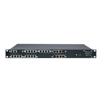
Gateway and E-SBC (hereafter, referred to as device). Product Overview AudioCodes Mediant 1000B Gateway and E- SBC, hereafter referred to as device , offers a complete connectivity solution for small-to-medium sized enterprises. The device connects IP- PBXs to any SIP trunking service provider. It offers superior performance in connecting any SIP to SIP environment, legacy TDM-based PBX systems to IP networks, and IP-PBXs to the PSTN in a modular 1U platform. -
Page 40: Typographical Conventions
CHAPTER 1 Introduction Mediant 1000 Gateway & E-SBC | User's Manual Typographical Conventions This document uses the following typographical conventions to convey information: Table 1-1: Typographical Conventions Convention Description Example Text enclosed by a Indicates Web interface parameters. From the 'Debug Level'... - Page 41 CHAPTER 1 Introduction Mediant 1000 Gateway & E-SBC | User's Manual The following table describes the main configuration concepts and terminology. Table 1-2: Configuration Concepts and Terminology Configuration Description Terms IP Group The IP Group is a logical representation of the SIP entity (UA) with which the device receives and sends calls.
- Page 42 CHAPTER 1 Introduction Mediant 1000 Gateway & E-SBC | User's Manual Configuration Description Terms Multiple SRDs are required only for multi-tenant deployments, where it "splits" the device into multiple logical devices. For multiple SRDs, the SRD can be configured with a Sharing Policy. The Sharing Policy simply means whether the SRD's resources (SIP Interfaces, IP Groups, and Proxy Sets) can be used by other SRDs.
- Page 43 CHAPTER 1 Introduction Mediant 1000 Gateway & E-SBC | User's Manual Configuration Description Terms Inbound manipulation lets you manipulate the user part of the SIP URI for source (e.g., in the SIP From header) and destination (e.g., in the Request- URI line) in the incoming SIP dialog request. Outbound manipulation lets you manipulate the user part of the Request-URI for source (e.g., in the SIP From...
-
Page 44: Gateway Application
CHAPTER 1 Introduction Mediant 1000 Gateway & E-SBC | User's Manual The main configuration entities and their involvement in the call processing is summarized in following figure. The figure is used only as an example to provide basic understanding of the configuration terminology. - Page 45 CHAPTER 1 Introduction Mediant 1000 Gateway & E-SBC | User's Manual The following table describes the main configuration concepts and terminology. Table 1-3: Configuration Concepts and Terminology Configuration Terms Description IP Groups The IP Group is a logical representation of the SIP entity (UA) with which the device receives and sends calls.
- Page 46 CHAPTER 1 Introduction Mediant 1000 Gateway & E-SBC | User's Manual Configuration Terms Description IP Profiles The IP Profile is an optional configuration entity that defines a wide range of call settings for a specific SIP entity (IP Group). The IP...
-
Page 47: Part I
Part I Getting Started with Initial Connectivity... -
Page 48: Introduction
CHAPTER 2 Introduction Mediant 1000 Gateway & E-SBC | User's Manual Introduction This part describes how to initially access the device's management interface and change its default IP address to correspond with your networking scheme. - 10 -... -
Page 49: Default Ip Address
CHAPTER 3 Default IP Address Mediant 1000 Gateway & E-SBC | User's Manual Default IP Address The device is shipped with a factory default networking address for operations, administration, maintenance, and provisioning (OAMP), through its LAN interface, as shown in the table below. -
Page 50: Configuring Voip Lan Interface For Oamp
CHAPTER 4 Configuring VoIP LAN Interface for OAMP Mediant 1000 Gateway & E-SBC | User's Manual Configuring VoIP LAN Interface for OAMP You can change the device's default OAMP IP address, using any of the following methods: ■ Embedded HTTP/S-based Web server (see Web Interface) ■... -
Page 51: Changing Oamp Address Through Cli
CHAPTER 4 Configuring VoIP LAN Interface for OAMP Mediant 1000 Gateway & E-SBC | User's Manual In the 'Username' and 'Password' fields, enter the case-sensitive, default login username ("Admin") and password ("Admin"). Click Log In. Configure the Ethernet port(s) that you want to use for the OAMP interface: In the Ethernet Groups table, configure an Ethernet Group by assigning it up to two ports (two ports provide optional, port-pair redundancy). - Page 52 CHAPTER 4 Configuring VoIP LAN Interface for OAMP Mediant 1000 Gateway & E-SBC | User's Manual ➢ To configure the OAMP IP address through CLI: Connect the RS-232 port of the device to the serial communication port on your computer. For more information, refer to the Hardware Installation Manual.
-
Page 53: Changing Oamp Address Through Ini File
CHAPTER 4 Configuring VoIP LAN Interface for OAMP Mediant 1000 Gateway & E-SBC | User's Manual Configure the prefix length: (network-if-0)# prefix-length <prefix length / subnet mask, e.g., 16> Configure the Default Gateway address: (network-if-0)# gateway <IP address> Apply your settings: (network-if-0)# activate Cable the device to your network. -
Page 54: Management Tools
Part II Management Tools... -
Page 55: Introduction
CHAPTER 5 Introduction Mediant 1000 Gateway & E-SBC | User's Manual Introduction This part describes the various management tools that you can use to configure the device: ■ Embedded HTTP/S-based Web server - see Web-based Management ■ Embedded Command Line Interface (CLI) - see CLI-Based Management ■... -
Page 56: Web-Based Management
CHAPTER 6 Web-Based Management Mediant 1000 Gateway & E-SBC | User's Manual Web-Based Management The device provides an embedded Web server (hereafter referred to as Web interface), supporting fault management, configuration, accounting, performance, and security (FCAPS). The Web interface provides a user-friendly, graphical user interface (GUI), which can be accessed using any standard Web browser. -
Page 57: Areas Of The Gui
CHAPTER 6 Web-Based Management Mediant 1000 Gateway & E-SBC | User's Manual In the 'Username' and 'Password' fields, enter the username and password, respectively. If you want the Web browser to remember your username, select the 'Remember Me' check box and then agree to the browser's prompt (depending on your browser). On your next login attempt, the 'Username' field is automatically populated with your username. - Page 58 CHAPTER 6 Web-Based Management Mediant 1000 Gateway & E-SBC | User's Manual Table 6-1: Description of the Web GUI Areas Item# Description Company logo. To customize the logo, see Replacing the Corporate Logo. If you click the logo, the Topology View page opens (see...
- Page 59 CHAPTER 6 Web-Based Management Mediant 1000 Gateway & E-SBC | User's Manual Item# Description Alarm bell icon displaying the number of active alarms generated by the device. The color of the number indicates the highest severity of an active alarm. If you click the icon, the Active Alarms table is displayed.
-
Page 60: Accessing Configuration Pages From Navigation Tree
CHAPTER 6 Web-Based Management Mediant 1000 Gateway & E-SBC | User's Manual Item# Description ■ Troubleshoot menu: Troubleshoot tab SRD filter. When your configuration includes multiple SRDs, you can filter tables in the Web interface by SRD. For more information, see... - Page 61 CHAPTER 6 Web-Based Management Mediant 1000 Gateway & E-SBC | User's Manual When you open the Navigation tree, folders containing commonly required items are opened by default, allowing quick access to their pages. Items that open pages containing tables provide the following indications in the Navigation tree: ■...
-
Page 62: Configuring Stand-Alone Parameters
CHAPTER 6 Web-Based Management Mediant 1000 Gateway & E-SBC | User's Manual Depending on the access level (e.g., Monitor level) of your Web user account, certain pages may not be accessible or may be read-only (see Configuring Management User Accounts). For read-only privileges: ●... -
Page 63: Configuring Table Parameters
CHAPTER 6 Web-Based Management Mediant 1000 Gateway & E-SBC | User's Manual Click Yes to confirm; the changes are save to flash memory. ● If a device reset is required: On the toolbar, click Reset; the Maintenance Actions page opens. Click Reset; the device saves the changes to flash memory and then resets. -
Page 64: Adding Table Rows
CHAPTER 6 Web-Based Management Mediant 1000 Gateway & E-SBC | User's Manual Item# Button Description Adds a new row to the table (see Adding Table Rows). Modifies the selected row (see Modifying Table Rows). Adds a new row with similar settings as the selected row (i.e., clones the row). -
Page 65: Assigning Rows From Other Tables
CHAPTER 6 Web-Based Management Mediant 1000 Gateway & E-SBC | User's Manual If the Save button is surrounded by a red border, you must save your settings to flash memory, otherwise they are discarded if the device resets (without a save to flash) or powers off. -
Page 66: Modifying Table Rows
CHAPTER 6 Web-Based Management Mediant 1000 Gateway & E-SBC | User's Manual The table (e.g., IP Groups table) and dialog box in which the Add new option was selected is minimized to the bottom-left corner of the Web interface and a dialog box appears for adding a new row in the referenced-table (e.g., Proxy Sets table). -
Page 67: Invalid Value Indications
CHAPTER 6 Web-Based Management Mediant 1000 Gateway & E-SBC | User's Manual Click Yes, Delete; the row is removed from the table and the total number of configured rows that is displayed next to the page title and page item in the Navigation tree is updated to reflect the deletion. - Page 68 CHAPTER 6 Web-Based Management Mediant 1000 Gateway & E-SBC | User's Manual ■ Parameters that reference rows of other configuration tables that are configured with invalid values: If a row has a parameter that references a row of another table that has a...
-
Page 69: Viewing Table Rows
CHAPTER 6 Web-Based Management Mediant 1000 Gateway & E-SBC | User's Manual If you assign a non-mandatory parameter with a referenced row and then later delete the referenced row (in the table in which the row is configured), the parameter's value auto- matically changes to an empty field (i.e., no row assigned). -
Page 70: Changing Index Position Of Table Rows
CHAPTER 6 Web-Based Management Mediant 1000 Gateway & E-SBC | User's Manual To sort the column in descending order, click the column name again; only the down arrow is displayed in a darker shade of color, indicating that the column is sorted in descending order: Changing Index Position of Table Rows You can change the position (index) of rows in tables. -
Page 71: Searching For Configuration Parameters
CHAPTER 6 Web-Based Management Mediant 1000 Gateway & E-SBC | User's Manual Table 6-4: Table Search Tool Description Item# Description 'Specify Columns' drop-down list for selecting the table column (parameter) in which to do the search. By default, the search is done in all columns. -
Page 72: Getting Help
CHAPTER 6 Web-Based Management Mediant 1000 Gateway & E-SBC | User's Manual The search key can include only alphanumerics, periods, and spaces. The use of other characters are invalid. ➢ To search for a parameter: In the search box, enter the search key (parameter name or value). -
Page 73: Customizing The Web Interface
SDP "o" line (see the SIPSDPSessionOwner parameter), and Subject header (see the SIPSubject parameter). Replacing the Corporate Logo You can replace the default corporate logo image (i.e., AudioCodes logo) that is displayed in the Web interface. The logo appears in the following Web areas: ■... -
Page 74: Replacing The Corporate Logo With An Image
CHAPTER 6 Web-Based Management Mediant 1000 Gateway & E-SBC | User's Manual You can replace the logo with one of the following: ■ A different image (see Replacing the Corporate Logo with an Image) ■ Text (see Replacing the Corporate Logo with... -
Page 75: Restoring The Default Corporate Logo Image
You can customize the label that appears on the tab of the Web browser that you use to open the device's Web interface. By default, the tab displays "AudioCodes". You can change this to display either the IP address of the device or any customized text. -
Page 76: Customizing The Product Name
CHAPTER 6 Web-Based Management Mediant 1000 Gateway & E-SBC | User's Manual If you have never configured the WebLogoText parameter, you can omit it from the ini file. If you have configured it before, then set it to an empty value, as shown above. -
Page 77: Customizing The Favicon
CHAPTER 6 Web-Based Management Mediant 1000 Gateway & E-SBC | User's Manual UseProductName = 1 UserProductName = < name > Load the ini file using the Auxiliary Files page (see Loading Auxiliary Files). Reset the device with a save-to-flash for your settings to take effect. -
Page 78: Creating A Login Welcome Message
CHAPTER 6 Web-Based Management Mediant 1000 Gateway & E-SBC | User's Manual Click Cmd Shell. In the 'Command Line' field, type the following, and then click Enter: CTACI FAVICON Creating a Login Welcome Message You can create a personalized welcome message that is displayed on the Web Login screen. The message always begins with the title "Note"... -
Page 79: Configuring Additional Management Interfaces
CHAPTER 6 Web-Based Management Mediant 1000 Gateway & E-SBC | User's Manual Configuring Additional Management Interfaces The Additional Management Interfaces table lets you configure up to 16 management interfaces, in addition to the OAMP management interface configured in the IP Interfaces table. Multiple management interfaces lets you remotely access the device's management interfaces (see note below) through different IP addresses. -
Page 80: Configuring Management User Accounts
CHAPTER 6 Web-Based Management Mediant 1000 Gateway & E-SBC | User's Manual Parameter Description ■ Only Control- and/or Media-type IP network interfaces can be associated with additional management interfaces. ■ An IP network interface can be associated with only one additional management interface. - Page 81 CHAPTER 6 Web-Based Management Mediant 1000 Gateway & E-SBC | User's Manual Numeric User Level Representation Privileges in RADIUS Note: Only Master users can delete Master users. If only one Master user exists, it can be deleted only by itself. Administrator...
- Page 82 CHAPTER 6 Web-Based Management Mediant 1000 Gateway & E-SBC | User's Manual The following procedure describes how to configure user accounts through the Web interface. You can also configure it through ini file [WebUsers] or CLI (configure system > user). ➢...
- Page 83 CHAPTER 6 Web-Based Management Mediant 1000 Gateway & E-SBC | User's Manual Parameter Description ■ For security, password characters are not shown in the Web interface and ini file. In the Web interface, they are displayed as dots when you enter the password and then once applied, the password is displayed as an asterisk (*) in the table.
- Page 84 CHAPTER 6 Web-Based Management Mediant 1000 Gateway & E-SBC | User's Manual Parameter Description ■ Valid = User can log in to the Web interface as normal. ■ Failed Login = The state is automatically set for users that exceed a user-defined number of failed login attempts, set by...
- Page 85 CHAPTER 6 Web-Based Management Mediant 1000 Gateway & E-SBC | User's Manual Parameter Description Note: After logging in with your new password, you must save your settings, by clicking the Save button on the Web interface's toolbar. If not, the next time you attempt to log in, you will be prompted again to change the expired password.
-
Page 86: Customizing Access Levels Per Web Page
CHAPTER 6 Web-Based Management Mediant 1000 Gateway & E-SBC | User's Manual Parameter Description The valid value is 0 to 100000, where 0 means that the user can do as many login failures without getting blocked. The default is according to the settings of the 'Deny Authentication Timer'... - Page 87 CHAPTER 6 Web-Based Management Mediant 1000 Gateway & E-SBC | User's Manual Page Name Read-Write Access Level Read-Only Access Level Description Firewall Security Administrator Monitor Assigns read- write privileges to Security Administrator users for the Firewall page. As this is the...
-
Page 88: Displaying Login Information Upon Login
CHAPTER 6 Web-Based Management Mediant 1000 Gateway & E-SBC | User's Manual Configure the rule according to the parameters described in the table below. Click Apply, and then save your settings to flash memory. Table 6-9: Customize Access Level Table Parameter Descriptions... -
Page 89: Viewing Logged-In User Information
CHAPTER 6 Web-Based Management Mediant 1000 Gateway & E-SBC | User's Manual Once enabled, each time you login to the device, the Login Information window is displayed, as shown in the example below: To close the window, click Close. Viewing Logged-In User Information The username of the currently logged in user is displayed in the top-right corner of the Web interface. -
Page 90: Changing Login Password By All User Levels
CHAPTER 6 Web-Based Management Mediant 1000 Gateway & E-SBC | User's Manual You can only perform the configuration described in this section if you are a management user with Security Administrator level or Master level. For more information, see Configuring Management User Accounts. -
Page 91: Configuring Secured (Https) Web
CHAPTER 6 Web-Based Management Mediant 1000 Gateway & E-SBC | User's Manual ● Users with Security Administrator level or Master level can also change passwords for themselves and for other user levels in the Local Users table (see Configuring Management User Accounts). -
Page 92: Configuring Csrf Protection
CHAPTER 6 Web-Based Management Mediant 1000 Gateway & E-SBC | User's Manual ➢ To configure secure (HTTPS) Web access: Open the Web Settings page (Setup menu > Administration tab > Web & CLI folder > Web Settings). Under the General group, configure the following: From the 'Secured Web Connection (HTTPS)' drop-down list, select HTTPS Only. -
Page 93: Configuring Web And Telnet Access List
CHAPTER 6 Web-Based Management Mediant 1000 Gateway & E-SBC | User's Manual ➢ To log in to the Web interface using CAC: Insert the Common Access Card into the card reader. Enter the password only. As some browsers require that the username be provided, it’s recommended to enter the username with an arbitrary value. -
Page 94: Cli-Based Management
CHAPTER 7 CLI-Based Management Mediant 1000 Gateway & E-SBC | User's Manual CLI-Based Management This chapter provides an overview of the CLI-based management and provides configuration relating to CLI management. ● By default, CLI is disabled for security purposes. ● The CLI provides two access modes - Basic mode (basic commands) and Privileged mode (all commands). -
Page 95: Enabling Ssh With Rsa Public Key For Cli
CHAPTER 7 CLI-Based Management Mediant 1000 Gateway & E-SBC | User's Manual Enabling SSH with RSA Public Key for CLI Unless configured for TLS, Telnet is not secure as it requires passwords to be transmitted in clear text. To overcome this, you can use Secure SHell (SSH) which is the de-facto standard for secure CLI. -
Page 96: Configuring Maximum Telnet/Ssh Sessions
CHAPTER 7 CLI-Based Management Mediant 1000 Gateway & E-SBC | User's Manual On the CLI Settings page, do the following: From the 'Enable SSH Server' drop-down list, select Enable. For additional security, you can configure the 'Public Key' field to Enable. This ensures that SSH access is only possible by using the RSA key and not by username and password. -
Page 97: Establishing A Cli Session
CHAPTER 7 CLI-Based Management Mediant 1000 Gateway & E-SBC | User's Manual ● Before changing the setting, make sure that not more than the number of sessions that you want to configure are currently active; otherwise, the new setting will not take effect. -
Page 98: Viewing Current Cli Sessions
CHAPTER 7 CLI-Based Management Mediant 1000 Gateway & E-SBC | User's Manual > enable At the prompt, type the password again, and then press Enter: Password: Admin Viewing Current CLI Sessions You can view users that are currently logged in to the device's CLI. This applies to users logged in to the CLI through RS-232 (console), Telnet, or SSH. -
Page 99: Configuring Displayed Output Lines In Cli Terminal Window
CHAPTER 7 CLI-Based Management Mediant 1000 Gateway & E-SBC | User's Manual Configuring Displayed Output Lines in CLI Terminal Window You can configure the maximum number of lines (height) displayed in the terminal window for the output of CLI commands (Telnet and SSH). The number of displayed lines can be from 0 to 65,535, or determined by re-sizing the terminal window by mouse-dragging the window's border. -
Page 100: Configuring Password Display In Cli
CHAPTER 7 CLI-Based Management Mediant 1000 Gateway & E-SBC | User's Manual Configuring Password Display in CLI You can enable the deviceto display passwords in the CLI's show running-config output in encrypted (obscured) format instead of in plain text. When passwords are displayed encrypted, the word "obscured"... -
Page 101: Snmp-Based Management
Mediant 1000 Gateway & E-SBC | User's Manual SNMP-Based Management The device provides an embedded SNMP agent that lets you manage it using AudioCodes One Voice Operations Center (OVOC) or a third-party SNMP manager. The SNMP agent supports standard and proprietary Management Information Base (MIBs). All supported MIB files are supplied to customers as part of the release. - Page 102 CHAPTER 8 SNMP-Based Management Mediant 1000 Gateway & E-SBC | User's Manual Configure SNMP community strings for access privileges: ● Under the Read Only Community Strings group, configure read-only community strings (see the table below). ● Under the Read/Write Community Strings group, configure read-write community strings (see the table below).
-
Page 103: Configuring Snmp Trap Destinations With Ip Addresses
CHAPTER 8 SNMP-Based Management Mediant 1000 Gateway & E-SBC | User's Manual Parameter Description The default is "public". For ini file configuration, x is 0 for the 'Read-Only 1' parameter. Read-Write Community Strings Defines read-write SNMP community strings. Up to five read-write community configure system >... - Page 104 CHAPTER 8 SNMP-Based Management Mediant 1000 Gateway & E-SBC | User's Manual Configure the SNMP trap manager according to the table below. Select the check boxes corresponding to the configured SNMP managers that you want to enable. Click Apply. ● Rows whose corresponding check boxes are cleared revert to default settings when you click Apply.
-
Page 105: Configuring An Snmp Trap Destination With Fqdn
CHAPTER 8 SNMP-Based Management Mediant 1000 Gateway & E-SBC | User's Manual Parameter Description 'Trap Enable' Activates the sending of traps to the SNMP Manager. [SNMPManagerTrapSendingEnable_ ■ [0] Disable ■ [1] Enable (default) Configuring an SNMP Trap Destination with FQDN Instead of configuring SNMP trap destinations (managers) with IP addresses in dotted-decimal... -
Page 106: Enabling Snmp Traps For Web Activity
CHAPTER 8 SNMP-Based Management Mediant 1000 Gateway & E-SBC | User's Manual Configure an IP address (in dotted-decimal notation) for one or more SNMP Trusted Managers. Select the check boxes corresponding to the configured SNMP Trusted Managers that you want to enable. - Page 107 CHAPTER 8 SNMP-Based Management Mediant 1000 Gateway & E-SBC | User's Manual Configure the SNMP V3 parameters according to the table below. Click Apply, and then reset the device with a save-to-flash for your settings to take effect. Table 8-3: SNMPv3 Users Table Parameters Description...
-
Page 108: Customizing Snmp Alarm Severity
CHAPTER 8 SNMP-Based Management Mediant 1000 Gateway & E-SBC | User's Manual Parameter Description 'Privacy Key' Privacy key. Keys can be entered in the form of a text password or long hex string. Keys are always persisted as long hex strings and keys are priv-key localized. - Page 109 CHAPTER 8 SNMP-Based Management Mediant 1000 Gateway & E-SBC | User's Manual Configure a rule according to the parameters described in the table below. Click Apply, and then reset the device with a save-to-flash for your settings to take effect. Table 8-4: Alarms Customization Parameter Descriptions...
- Page 110 CHAPTER 8 SNMP-Based Management Mediant 1000 Gateway & E-SBC | User's Manual Parameter Description ✔ If configured to any value other than Suppressed, the device always sends the alarm with the configured severity (regardless of condition). ■ [1] Indeterminate ■ [2] Warning ■...
- Page 111 CHAPTER 8 SNMP-Based Management Mediant 1000 Gateway & E-SBC | User's Manual Parameter Description ✔ To suppress the sending of a specific alarm severity: If the alarm has multiple severity levels (based on conditions), configure the 'Original Severity' parameter to the severity that you don't want the device to send.
-
Page 112: Ini File-Based Management
CHAPTER 9 INI File-Based Management Mediant 1000 Gateway & E-SBC | User's Manual INI File-Based Management You can configure the device through an ini file, which is a text-based file with an *.ini file extension name, created using any standard text-based editor such as Notepad. Once you have created an ini file with all your configuration settings, you need to install (load) it to the device to apply the configuration. - Page 113 CHAPTER 9 INI File-Based Management Mediant 1000 Gateway & E-SBC | User's Manual ● A Data line must end with a semicolon ";". ■ End-of-Table Mark: Indicates the end of the table. The same string used for the table’s title, preceded by a backslash "\", e.g., [\MY_TABLE_NAME].
-
Page 114: General Ini File Formatting Rules
CHAPTER 9 INI File-Based Management Mediant 1000 Gateway & E-SBC | User's Manual Do not include read-only parameters in the table ini file parameter. This can cause an error when loading the file to the device. General ini File Formatting Rules The ini file must adhere to the following formatting rules: ■... -
Page 115: Loading An Ini File To The Device
HTTP. These protocols are not secure and are vulnerable to potential hackers. To overcome this security threat, the AudioCodes DConvert utility allows you to binary-encode (encrypt) the ini file before loading it to the device. For more information, refer to the DConvert Utility User's Guide. -
Page 116: Ini Viewer And Editor Utility
CHAPTER 9 INI File-Based Management Mediant 1000 Gateway & E-SBC | User's Manual ● When you load an ini file to the device containing obscured passwords, the passwords are parsed and applied to the device. ● When you load an ini file to the device containing hidden passwords, the passwords are ignored. -
Page 117: Rest-Based Management
CHAPTER 10 REST-Based Management Mediant 1000 Gateway & E-SBC | User's Manual REST-Based Management You can manage the device through the Representational State Transfer (REST) architecture. REST is a Web-based access service, allowing you to access the device's management interface over HTTP/S. Developers can use the device's REST API to integrate the device into their solution and allow administrators to perform management and configuration tasks through automation scripts. - Page 118 CHAPTER 10 REST-Based Management Mediant 1000 Gateway & E-SBC | User's Manual ● If you know the URL of the resource, instead of accessing each resource menu, you can access it directly using the full URL path (e.g., /api/v1/alarms/active). ● For more information on REST API, refer to the document, REST API for Mediant Devices.
-
Page 119: General System Settings
Part III General System Settings... -
Page 120: Date And Time
CHAPTER 11 Date and Time Mediant 1000 Gateway & E-SBC | User's Manual Date and Time The date and time of the device can be configured manually or it can be obtained automatically from a Simple Network Time Protocol (SNTP) server. -
Page 121: Configuring Date And Time Manually
CHAPTER 11 Date and Time Mediant 1000 Gateway & E-SBC | User's Manual If the device does not receive a response from the NTP server, it polls the NTP server for 10 minutes. If there is still no response after this duration, the device declares the NTP server as unavailable and raises an SNMP alarm (acNTPServerStatusAlarm). -
Page 122: Configuring Daylight Saving Time
CHAPTER 11 Date and Time Mediant 1000 Gateway & E-SBC | User's Manual In the 'UTC Offset' fields (NTPServerUTCOffset), configure the time offset in relation to the UTC. For example, if your region is GMT +1 (an hour ahead), enter "1" in the 'Hours' field. -
Page 123: Configuring A Hostname For The Device
The device's SNMP interface's SysName object (under MIB-2) is set to the hostname. ■ TLS certificates used by the device for HTTPS-based communication with AudioCodes OVOC are issued with a hostname (instead of an IP address). For certificate signing requests (CSR) with a Certification Authority (CA), the hostname is used as the Common Name (CN or Subject Name) and Subject Alternative Name (SAN). -
Page 124: General Voip Configuration
Part IV General VoIP Configuration... -
Page 125: Network
CHAPTER 13 Network Mediant 1000 Gateway & E-SBC | User's Manual Network This section describes network-related configuration. Building and Viewing your Network Topology The Network view lets you easily build and view your voice network topology entities, including IP network interfaces, Ethernet Devices (VLANs), Ethernet Groups, and physical Ethernet ports. The Topology view graphically displays these entities and the associations between them, giving you a better understanding of your network topology and configuration. - Page 126 CHAPTER 13 Network Mediant 1000 Gateway & E-SBC | User's Manual Item Description The IP Interface appears as an icon, displaying the application type ("OCM" for OAMP, "C" for Control, and "M" for Media), row index number, name, and IP address, as shown...
- Page 127 CHAPTER 13 Network Mediant 1000 Gateway & E-SBC | User's Manual Item Description Configure the Ethernet Devices as desired, and then click Apply; the Ethernet Devices table closes and you are returned to the Network View, displaying the newly added Ethernet Device.
-
Page 128: Configuring Physical Ethernet Ports
CHAPTER 13 Network Mediant 1000 Gateway & E-SBC | User's Manual Item Description The connectivity status of the port is indicated by the color of the icon: ■ Green: Network connectivity exists through port (port connected to network). ■ Red: No network connectivity through port (e.g., cable disconnected). - Page 129 CHAPTER 13 Network Mediant 1000 Gateway & E-SBC | User's Manual ● All LAN ports (including those of the optional SWX Expansion module) have the same MAC address, which is the MAC address of the device. ● Each Ethernet Group must have a unique VLAN ID in scenarios where the ports of multiple Ethernet Groups are connected to the same switch.
-
Page 130: Configuring Ethernet Port Groups
CHAPTER 13 Network Mediant 1000 Gateway & E-SBC | User's Manual Parameter Description 'Name' (Read-only) Displays the Ethernet port number. See the figure in the beginning of this section for the mapping between the GUI port port number and the physical port on the chassis. - Page 131 CHAPTER 13 Network Mediant 1000 Gateway & E-SBC | User's Manual The Ethernet Groups table also lets you configure the transmit (Tx) and receive (Rx) settings of the Ethernet ports per Ethernet Group. The Tx/Rx setting is applicable only to Ethernet Groups that contain two ports.
- Page 132 CHAPTER 13 Network Mediant 1000 Gateway & E-SBC | User's Manual Configure the Ethernet Group according to the parameters described in the table below. Click Apply, and then reset the device with a burn-to-flash for your settings to take effect. Table 13-3: Ethernet Groups Table Parameter Descriptions...
-
Page 133: Configuring Underlying Ethernet Devices
CHAPTER 13 Network Mediant 1000 Gateway & E-SBC | User's Manual Parameter Description 'Member 2' Assigns the second port to the Ethernet Group. To assign no port, set this field to None. member2 Note: Before you can re-assign a port to a different Ethernet Group, you [EtherGroupTable_ must first remove the port from its current Ethernet Group. - Page 134 CHAPTER 13 Network Mediant 1000 Gateway & E-SBC | User's Manual Configure an Ethernet Device according to the parameters described in the table below. Click Apply. Table 13-4: Ethernet Devices Table Parameter Descriptions Parameter Description 'Index' Defines an index number for the new table row.
-
Page 135: Configuring Ip Network Interfaces
CHAPTER 13 Network Mediant 1000 Gateway & E-SBC | User's Manual Parameter Description ■ [1] Tagged = (Default for new Ethernet Devices) The Ethernet Device accepts packets that have the same VLAN ID as the Ethernet Device and sends packets with this VLAN ID. For all... - Page 136 CHAPTER 13 Network Mediant 1000 Gateway & E-SBC | User's Manual The device is shipped with a default OAMP interface (see Default IP Address). The IP Interfaces table lets you change this OAMP interface and configure additional network interfaces for control and media, if necessary.
- Page 137 CHAPTER 13 Network Mediant 1000 Gateway & E-SBC | User's Manual ■ IP interface types can be combined: ● Example 1: One combined OAMP-Media-Control interface with an IPv4 address ◆ ● Example 2: One OAMP-type interface with an IPv4 address ◆...
- Page 138 CHAPTER 13 Network Mediant 1000 Gateway & E-SBC | User's Manual Configure the IP network interface according to the parameters described in the table below. Click Apply. ● If you modify the OAMP interface's address, after clicking Apply you will lose connectivity with the device and need to access the device with the new address.
- Page 139 CHAPTER 13 Network Mediant 1000 Gateway & E-SBC | User's Manual Parameter Description ■ Only one IP network interface can be configured with OAMP in this table. To configure additional management interfaces, see Configuring Additional Management Interfaces. 'Ethernet Device' Assigns an Ethernet Device to the IP interface. An...
-
Page 140: Networking Configuration Examples
CHAPTER 13 Network Mediant 1000 Gateway & E-SBC | User's Manual Parameter Description The valid value of the prefix length depends on the IP address version: ■ IPv4: 0 to 31 (default is 16) ■ IPv6: 64 (default is 64) 'Default Gateway' Defines the IP address of the default gateway for the IP interface. - Page 141 CHAPTER 13 Network Mediant 1000 Gateway & E-SBC | User's Manual ■ Multiple interfaces, one per application type: The IP Interfaces table is configured with three interfaces, each for a different application type (one for OAMP, one for Call Control, and one for RTP Media), and each with a different VLAN...
- Page 142 CHAPTER 13 Network Mediant 1000 Gateway & E-SBC | User's Manual Index Destination Prefix Length Gateway 176.85.49.0 192.168.0.10 The NTP application is configured (through the ini file) to serve as OAMP applications: EnableNTPasOAM = 1 Configure Layer-2 QoS mapping in the QoS Mapping table. Packets sent with the configured...
-
Page 143: Configuring Static Ip Routes
CHAPTER 13 Network Mediant 1000 Gateway & E-SBC | User's Manual Configuring Static IP Routes The Static Routes table lets you configure up to 30 static IP routing rules. Static routes let you communicate with LAN networks that are not located behind the Default Gateway that is specified for an IP network interface in the IP Interfaces table, from which the packets are sent. -
Page 144: Configuration Example Of Static Ip Routes
CHAPTER 13 Network Mediant 1000 Gateway & E-SBC | User's Manual Table 13-6: Static Routes Table Parameter Descriptions Parameter Description 'Index' Defines an index number for the new table row. [StaticRouteTable_ The valid value is 0 to 29. Index] Note: Each row must be configured with a unique index. -
Page 145: Troubleshooting The Static Routes Table
CHAPTER 13 Network Mediant 1000 Gateway & E-SBC | User's Manual Note the following configuration: ■ The static route is configured with a subnet mask of 24 (255.255.255.0), enabling the device to use the static route to send all packets destined for 10.1.1.x to this gateway and therefore, to the network in which the softswitch resides. -
Page 146: Network Address Translation Support
CHAPTER 13 Network Mediant 1000 Gateway & E-SBC | User's Manual If a static route is required to access OAMP applications (for remote management, for example) and the route is not configured correctly, the route is not added and the device is not accessible remotely. -
Page 147: Configuring A Static Nat Ip Address For All Interfaces
CHAPTER 13 Network Mediant 1000 Gateway & E-SBC | User's Manual Configuring a Static NAT IP Address for All Interfaces You can configure a global (public) IP address of the router to enable static NAT between the device and the Internet for all network interfaces. The device replaces the source IP address for media of all outgoing SIP messages sent on any of its network interfaces to this public IP address. -
Page 148: Remote Ua Behind Nat
CHAPTER 13 Network Mediant 1000 Gateway & E-SBC | User's Manual Click Apply, and then save your settings to flash memory. Table 13-7: NAT Translation Table Parameter Descriptions Parameter Description Source 'Index' Defines an index number for the new table row. -
Page 149: Sip Signaling Messages
CHAPTER 13 Network Mediant 1000 Gateway & E-SBC | User's Manual SIP Signaling Messages By default, the device resolves NAT issues for SIP signaling, using its NAT Detection mechanism. The NAT Detection mechanism checks whether the endpoint is located behind NAT by comparing the source IP address of the incoming UDP/TCP packet (in which the SIP message is received) with the IP address in the SIP Contact header. - Page 150 CHAPTER 13 Network Mediant 1000 Gateway & E-SBC | User's Manual First Incoming Packet Mechanism In scenarios where the remote user agent (UA) resides behind a NAT server, it’s possible that the device, if not configured for NAT traversal, will send the media (RTP, RTCP and T.38) streams to an invalid IP address and UDP port.
-
Page 151: Robust Receipt Of Media Streams By Media Latching
CHAPTER 13 Network Mediant 1000 Gateway & E-SBC | User's Manual Configure the time interval during which the device sends No-Op packets when silence occurs (i.e., no RTP or T.38 traffic), using the [NoOpInterval] parameter. For RTP No-Op packets, configure the payload type of the No-Op packets, using the [RTPNoOpPayloadType] parameter. - Page 152 CHAPTER 13 Network Mediant 1000 Gateway & E-SBC | User's Manual Table 13-8: Traffic/Network Types and Priority Class-of-Service Application Traffic / Network Types (Priority) Debugging interface Management Bronze Telnet Management Bronze Web server (HTTP) Management Bronze SNMP GET/SET Management Bronze Web server (HTTPS)
-
Page 153: Configuring Diffserv-To-Vlan Priority Mapping
CHAPTER 13 Network Mediant 1000 Gateway & E-SBC | User's Manual Configure DiffServ values per CoS according to the parameters described in the table below. Click Apply, and then save your settings to flash memory. Table 13-9: QoS Settings Parameter Descriptions... -
Page 154: Configuring Icmp Messages
CHAPTER 13 Network Mediant 1000 Gateway & E-SBC | User's Manual The following procedure describes how to configure DiffServ-to-VLAN priority mapping through the Web interface. You can also configure it through ini file [DiffServToVlanPriority] or CLI (configure network > qos vlan-mapping). -
Page 155: Dns
CHAPTER 13 Network Mediant 1000 Gateway & E-SBC | User's Manual This feature is applicable to IPv4 and IPv6 addressing schemes. ➢ To configure handling of ICMP messages: Open the Network Settings page (Setup menu > IP Network tab > Advanced folder >... -
Page 156: Configuring The Internal Dns Table
CHAPTER 13 Network Mediant 1000 Gateway & E-SBC | User's Manual ➢ To modify the default DNS server addresses: Open the DNS Settings page (Setup menu > IP Network tab > DNS folder > DNS Settings). In the 'Default Primary DNS Server IP' field, configure the address of the default primary DNS server. - Page 157 CHAPTER 13 Network Mediant 1000 Gateway & E-SBC | User's Manual Configure a DNS rule according to the parameters described in the table below. Click Apply. Table 13-11:Internal DNS Table Parameter Description Parameter Description 'Index' Defines an index number for the new table row.
-
Page 158: Configuring The Internal Srv Table
CHAPTER 13 Network Mediant 1000 Gateway & E-SBC | User's Manual Configuring the Internal SRV Table The Internal SRV table lets you configure up to 10 SRV rows. The table is used to resolve hostnames into DNS A-Records. You can assign three different A-Records per hostname, where each A-Record includes the hostname, priority, weight, and port. -
Page 159: Open Solution Network (Osn) Server
CHAPTER 13 Network Mediant 1000 Gateway & E-SBC | User's Manual Parameter Description 'Transport Type' Defines the transport type. ■ [0] UDP (default) transport-type ■ [1] TCP [Srv2Ip_ ■ [2] TLS TransportType] 1st/2nd/3rd Entry 'DNS Name (1-3)' Defines the first, second or third DNS A-Record to which the hostname is translated. -
Page 160: Disabling Internal Switch Port For Osn
CHAPTER 13 Network Mediant 1000 Gateway & E-SBC | User's Manual ➢ To configure a Native VLAN for the OSN: Open the Network Settings page (Setup menu > IP Network tab > Advanced folder > Network Settings). Scroll down to the OSN group: In the 'OSN Native VLAN ID' field, configure the VLAN ID, and then click Apply. -
Page 161: Security
CHAPTER 14 Security Mediant 1000 Gateway & E-SBC | User's Manual Security This section describes the VoIP security-related configuration. Configuring SSL/TLS Certificates The TLS Contexts table lets you configure X.509 certificates which are used for secure management of the device, secure SIP transactions, and other security applications. - Page 162 CHAPTER 14 Security Mediant 1000 Gateway & E-SBC | User's Manual ■ Online Certificate Status Protocol (OCSP). Some Public-Key Infrastructures (PKI) can revoke a certificate after it has been issued. You can configure the device to check whether a peer's certificate has been revoked, using the OCSP. When OCSP is enabled, the device queries the OCSP server for revocation information whenever a peer certificate is received (TLS client mode, or TLS server mode with mutual authentication).
- Page 163 CHAPTER 14 Security Mediant 1000 Gateway & E-SBC | User's Manual Configure the TLS Context according to the parameters described in the table below. Click Apply, and then reset the device with a save-to-flash for your settings to take effect. Table 14-1: TLS Contexts Parameter Descriptions...
- Page 164 CHAPTER 14 Security Mediant 1000 Gateway & E-SBC | User's Manual Parameter Description ■ [1] DTLSv1.0 ■ [2] DTLSv1.2 For more information on WebRTC, see WebRTC. Note: The parameter is applicable only to the SBC application. 'Cipher Server' Defines the supported cipher suite for the TLS server (in OpenSSL cipher list format).
-
Page 165: Assigning Csr-Based Certificates To Tls Contexts
CHAPTER 14 Security Mediant 1000 Gateway & E-SBC | User's Manual Parameter Description 'Secondary OCSP Server' Defines the IP address (in dotted-decimal notation) of the secondary OCSP server (optional). ocsp-server-secondary The default is 0.0.0.0. [TLSContexts_ OcspServerSecondary] 'OCSP Port' Defines the OCSP server's TCP port number. - Page 166 CHAPTER 14 Security Mediant 1000 Gateway & E-SBC | User's Manual ● Fill in the fields according to you security provider's instructions. ● If you leave the 'Common Name [CN]' field empty, the device generates the CSR with the default Common Name (CN=ACL_<6-digit serial number of device>).
-
Page 167: Viewing Certificate Information
CHAPTER 14 Security Mediant 1000 Gateway & E-SBC | User's Manual Select the required TLS Context row. Click the Certificate Information link located below the table. Make sure that the 'Status' field displays "OK"; otherwise, consult with your security administrator: ●... -
Page 168: Assigning Externally Created Private Keys To Tls Contexts
CHAPTER 14 Security Mediant 1000 Gateway & E-SBC | User's Manual Assigning Externally Created Private Keys to TLS Contexts The following procedure describes how to assign an externally created private key to a TLS Context. ➢ To assign an externally created private key to a TLS Context: Obtain a private key in either textual PEM (PKCS #7) or PFX (PKCS #12) format (typically provided by your security administrator). -
Page 169: Generating Private Keys For Tls Contexts
CHAPTER 14 Security Mediant 1000 Gateway & E-SBC | User's Manual Open the TLS Contexts table (see Configuring TLS Certificate Contexts). In the table, select the required TLS Context index row, and then click the Change Certificate link located below the table; the Change Certificates page appears. -
Page 170: Creating Self-Signed Certificates For Tls Contexts
CHAPTER 14 Security Mediant 1000 Gateway & E-SBC | User's Manual From the 'Private Key Size' drop-down list, select the desired private key size (in bits) for RSA public-key encryption for newly self-signed generated keys: ● ● ● 1024 (default) ●... -
Page 171: Importing Certificates Into Trusted Root Certificate Store
CHAPTER 14 Security Mediant 1000 Gateway & E-SBC | User's Manual Under the Certificate Signing Request group, in the 'Common Name [CN]' field, enter the fully-qualified DNS name (FQDN) as the certificate subject. Alternatively (or in addition), if you want to generate a self-signed SAN certificate (with multiple subject alternate names), then from the 'Subject Alternative Name [SAN]' drop-down list, select the type of SAN (e-mail address, DNS hostname, URI, or IP address), and then enter the relevant value. -
Page 172: Configuring Mutual Tls Authentication
CHAPTER 14 Security Mediant 1000 Gateway & E-SBC | User's Manual You can also import multiple TLS root certificates in bulk from a single file. Each certificate in the file must be Base64 encoded (PEM). When copying-and-pasting the certificates into the file, each Base64 ASCII encoded certificate string must be enclosed between "-----BEGIN CERTIFICATE---... -
Page 173: Tls For Sip Clients
CHAPTER 14 Security Mediant 1000 Gateway & E-SBC | User's Manual TLS for SIP Clients When Secure SIP (SIPS) is implemented using TLS, it is sometimes required to use two-way (mutual) authentication between the device and a SIP user agent (client). When the device acts as the TLS server in a specific connection, the device demands the authentication of the SIP client’s... -
Page 174: Configuring Tls Server Certificate Expiry Check
CHAPTER 14 Security Mediant 1000 Gateway & E-SBC | User's Manual When a user connects to the secured Web interface of the device: ■ If the user has a client certificate from a CA that is listed in the Trusted Root Certificate file, the connection is accepted and the user is prompted for the system password. - Page 175 Protocol: Any ✔ Action Upon Match: Block ● If the device needs to communicate with AudioCodes OVOC, you must also add rules to allow incoming traffic from OVOC. For more information, see Configuring Firewall Rules to Allow Incoming OVOC Traffic on page 141.
- Page 176 CHAPTER 14 Security Mediant 1000 Gateway & E-SBC | User's Manual Configure a firewall rule according to the parameters described in the table below. Click Apply, and then reset the device with a save-to-flash for your settings to take effect. Table 14-2: Firewall Table Parameter Descriptions...
- Page 177 CHAPTER 14 Security Mediant 1000 Gateway & E-SBC | User's Manual Parameter Description 'Start Port' Defines the first UDP/TCP port in the range of ports on the device on which the incoming packet is received. From the perspective of the remote IP start-port entity, this is the destination port.
- Page 178 CHAPTER 14 Security Mediant 1000 Gateway & E-SBC | User's Manual Parameter Description 'Packet Size' Defines the maximum allowed packet size. The valid range is 0 to 65535. packet- size Note: When filtering fragmented IP packets, this field relates to the overall [AccessList_ (re-assembled) packet size, and not to the size of each fragment.
-
Page 179: Configuring Firewall Rules To Allow Incoming Ovoc Traffic
Rule 5: Blocks all other traffic. Configuring Firewall Rules to Allow Incoming OVOC Traffic If the device needs to communicate with AudioCodes OVOC, you need to configure the device's firewall (Firewall table) with the below "allow" firewall rules to permit incoming traffic from OVOC. -
Page 180: Configuring Tls For Sip
CHAPTER 14 Security Mediant 1000 Gateway & E-SBC | User's Manual Acti- Pre- Pac- Byt- Sou- Spe- Inter- Sour- Pro- Upo- Index cific face ce IP Len- tocol Siz- Port Inter- Name Mat- face <OV Enabl <inter- Allo (HTT OC IP... - Page 181 CHAPTER 14 Security Mediant 1000 Gateway & E-SBC | User's Manual ● When a TLS connection with the device is initiated by a SIP client, the device also responds using TLS, regardless of whether or not TLS was configured. ● The device regulates the number of new concurrent TLS connections that can be established per second.
-
Page 182: Intrusion Detection System
CHAPTER 14 Security Mediant 1000 Gateway & E-SBC | User's Manual Intrusion Detection System The device's Intrusion Detection System (IDS) feature detects malicious attacks on the device and reacts accordingly. A remote host is considered malicious if it has reached or exceeded a user- defined threshold (counter) of specified malicious attacks. -
Page 183: Configuring Ids Policies
CHAPTER 14 Security Mediant 1000 Gateway & E-SBC | User's Manual Click Apply. Configuring IDS Policies An IDS Policy is configured using two tables with "parent-child" type relationship: ■ IDS Policies table ("parent"): Defines a name and provides a description for the IDS Policy. - Page 184 CHAPTER 14 Security Mediant 1000 Gateway & E-SBC | User's Manual Click Apply. Table 14-5: IDS Policies Table Parameter Descriptions Parameter Description 'Index' Defines an index number for the new table row. Note: Each row must be configured with a unique index.
- Page 185 CHAPTER 14 Security Mediant 1000 Gateway & E-SBC | User's Manual Parameter Description [IDSRule_RuleID] 'Reason' Defines the type of intrusion attack (malicious event). ■ [0] Any = All events listed below are considered as attacks and reason are counted together. [IDSRule_Reason] ■...
- Page 186 CHAPTER 14 Security Mediant 1000 Gateway & E-SBC | User's Manual Parameter Description ✔ Requests and responses without a matching transaction user (except ACK requests) ✔ Requests and responses without a matching transaction (except ACK requests) 'Threshold Scope' Defines the source of the attacker to consider in the device's detection count.
-
Page 187: Assigning Ids Policies
CHAPTER 14 Security Mediant 1000 Gateway & E-SBC | User's Manual Parameter Description 'Deny Period' Defines the duration (in sec) to keep the attacker on the blacklist, if configured using the 'Deny Threshold' parameter. deny-period The valid range is 0 to 1,000,000. The default is -1 (i.e., not [IDSRule_DenyPeriod] configured). - Page 188 CHAPTER 14 Security Mediant 1000 Gateway & E-SBC | User's Manual Parameter Description [IDSMatch_SIPInterface] The valid value is the ID of the SIP Interface. The following syntax is supported: ■ A comma-separated list of SIP Interface IDs (e.g., 1,3,4) ■ A hyphen "-" indicates a range of SIP Interfaces (e.g., 3,4-7 means IDs 3, and 4 through 7) ■...
-
Page 189: Viewing Ids Alarms
CHAPTER 14 Security Mediant 1000 Gateway & E-SBC | User's Manual Viewing IDS Alarms For the IDS feature, the device sends the following SNMP traps: ■ Traps that notify the detection of malicious attacks: ● acIDSPolicyAlarm: The device sends this alarm whenever a threshold of a specific IDS Policy rule is crossed. - Page 190 CHAPTER 14 Security Mediant 1000 Gateway & E-SBC | User's Manual The device also sends IDS notifications and alarms in Syslog messages to a Syslog server. This occurs only if you have configured Syslog (see Enabling Syslog). An example of a Syslog message...
-
Page 191: Configuring Sip Response Codes To Exclude From Ids
CHAPTER 14 Security Mediant 1000 Gateway & E-SBC | User's Manual Reason Description Syslog String Abnormal Flow Requests and responses without a matching flow-no-match-tu transaction user (except ACK requests) Requests and responses without a matching flow-no-match-transaction transaction (except ACK requests) Configuring SIP Response Codes to Exclude from IDS You can specify SIP response codes (reject reasons) that you want the IDS mechanism to ignore in its' count as reasons for SIP-dialog establishment failures. -
Page 192: Media
CHAPTER 15 Media Mediant 1000 Gateway & E-SBC | User's Manual Media This section describes media-related configuration. Configuring Voice Settings The section describes various voice- related configuration such as voice volume, silence suppression, and DTMF transport type. For a detailed description of these parameters, see Configuration Parameters Reference. -
Page 193: Fax And Modem Capabilities
CHAPTER 15 Media Mediant 1000 Gateway & E-SBC | User's Manual From the 'Echo Canceller' drop-down list (EnableEchoCanceller), select Enable. Open the Media Settings page (Setup menu > Signaling & Media tab > Media folder > Media Settings). From the 'Max Echo Canceller Length' drop-down list (MaxEchoCancellerLength), select the maximum echo path delay (tail length) for the echo canceller. -
Page 194: Fax/Modem Operating Modes
CHAPTER 15 Media Mediant 1000 Gateway & E-SBC | User's Manual Fax/Modem Operating Modes The device supports two modes of operation: ■ Fax/modem negotiation that is not performed during the establishment of the call. ■ Voice-band data (VBD) mode for V.152 implementation (see V.152... - Page 195 CHAPTER 15 Media Mediant 1000 Gateway & E-SBC | User's Manual T.38 can be configured in the following ways: ■ Switching to T.38 mode using SIP Re-INVITE messages (see Switching to T.38 Mode using Re-INVITE) ■ Automatically switching to T.38 mode without using SIP Re-INVITE messages (see Automatically Switching to T.38 Mode without SIP...
- Page 196 Call Parties belong to AudioCodes Devices: T.38-over-RTP method is used, whereby the device encapsulates the entire T.38 packet (payload with all its headers) in the sent RTP. For T.38 over RTP, AudioCodes devices use the proprietary identifier "AcUdptl" in the 'a=ftmp' line of the SDP. For example: o=AudioCodesGW 1357424688 1357424660 IN IP4 10.8.6.68...
-
Page 197: G.711 Fax / Modem Transport Mode
CHAPTER 15 Media Mediant 1000 Gateway & E-SBC | User's Manual ■ Device initiates a call: The device always sends the SDP offer with the proprietary token "AcUdpTl" in the 'fmtp' attribute. If the SDP answer includes the same token, the device employs the proprietary T.38-over-RTP mode;... -
Page 198: Fax/Modem Bypass Mode
CHAPTER 15 Media Mediant 1000 Gateway & E-SBC | User's Manual ■ Echo Canceller = on ■ Silence Compression = off ■ Echo Canceller Non-Linear Processor Mode = off ■ Dynamic Jitter Buffer Minimum Delay = 40 ■ Dynamic Jitter Buffer Optimization Factor = 13 When the device initiates a fax session using G.711, a ‘gpmd’... -
Page 199: Fax / Modem Nse Mode
G.711 packets with standard payload type (8 for G.711 A-Law and 0 for G.711 Mu-Law). In this mode, no Re-INVITE messages are sent. The voice channel is optimized for fax/modem transmission (same as for usual bypass mode). The following parameters that configure the payload type for the AudioCodes proprietary Bypass mode used... -
Page 200: Fax / Modem Transparent With Events Mode
CHAPTER 15 Media Mediant 1000 Gateway & E-SBC | User's Manual The Cisco gateway must include the following definition: modem passthrough nse payload-type 100 codec g711alaw ➢ To configure NSE mode: Open the Gateway General Settings page (Setup menu > Signaling & Media tab > Gateway folder >... -
Page 201: Fax / Modem Transparent Mode
CHAPTER 15 Media Mediant 1000 Gateway & E-SBC | User's Manual Fax / Modem Transparent Mode In this mode, fax and modem signals are transferred using the current voice coder without notifications to the user and without automatic adaptations. It's possible to use Profiles (see Coders and Profiles ) to apply certain adaptations to the channel used for fax / modem. -
Page 202: V.34 Fax Support
CHAPTER 15 Media Mediant 1000 Gateway & E-SBC | User's Manual ● Set the 'V.xx Modem Transport Type' parameters to Enable Bypass (VxxModemTransportType = 2). Configure the [FaxModemNTEMode] parameter to [1] (enables this feature). V.34 Fax Support V.34 fax machines can transmit data over IP to the remote side using various methods. The device supports the following modes for transporting V.34 fax data over IP:... -
Page 203: Relay Mode For T.30 And V.34 Faxes
CHAPTER 15 Media Mediant 1000 Gateway & E-SBC | User's Manual ● Set the 'V.34 Modem Transport Type' parameter to Enable Bypass [V34ModemTransportType = 2]. Configure the [V34FaxTransportType] parameter to [2] (Bypass). Relay Mode for T.30 and V.34 Faxes In this scenario, V.34 fax machines are forced to use their backward compatibility with T.30 faxes and operate in the slower T.30 mode. - Page 204 CHAPTER 15 Media Mediant 1000 Gateway & E-SBC | User's Manual ● 'V.22 Modem Transport Type' to Disable (V22ModemTransportType = 0). ● 'V.23 Modem Transport Type' to Disable (V23ModemTransportType = 0). ● 'V.32 Modem Transport Type' to Disable (V32ModemTransportType = 0).
-
Page 205: V.152 Support
CHAPTER 15 Media Mediant 1000 Gateway & E-SBC | User's Manual a=T38FaxMaxDatagram:122 a=T38FaxRateManagement:transferredTCF a=T38FaxUdpEC:t38UDPRedundancy V.152 Support The device supports the ITU-T recommendation V.152 (Procedures for Supporting Voice-Band Data over IP Networks). Voice-band data (VBD) is the transport of modem, facsimile, and text telephony signals over a voice channel of a packet network with a codec appropriate for such signals. -
Page 206: Configuring The Dynamic Jitter Buffer
CHAPTER 15 Media Mediant 1000 Gateway & E-SBC | User's Manual Configuring the Dynamic Jitter Buffer Voice frames are transmitted at a fixed rate. If the frames arrive at the other end at the same rate, voice quality is perceived as good. However, some frames may arrive slightly faster or slower than the other frames. -
Page 207: Comfort Noise Generation
CHAPTER 15 Media Mediant 1000 Gateway & E-SBC | User's Manual Set the 'Dynamic Jitter Buffer Minimum Delay' parameter (DJBufMinDelay) to the minimum delay (in msec) for the Dynamic Jitter Buffer. Set the 'Dynamic Jitter Buffer Optimization Factor' parameter (DJBufOptFactor) to the Dynamic Jitter Buffer frame error/delay optimization factor. - Page 208 CHAPTER 15 Media Mediant 1000 Gateway & E-SBC | User's Manual Set the 'Declare RFC 2833 in SDP' parameter to No (RxDTMFOption = 0). Set the 'First Tx DTMF Option' parameter to INFO Nortel (FirstTxDTMFOption = 1). DTMF digits are removed from the audio stream (and the 'DTMF Transport Type' parameter is automatically set to Mute DTMF).
-
Page 209: Configuring Rfc 2833 Payload
CHAPTER 15 Media Mediant 1000 Gateway & E-SBC | User's Manual DTMF digits are removed from the audio stream (and the 'DTMF Transport Type' parameter is automatically set to Mute DTMF). ● The device is always ready to receive DTMF packets over IP in all possible transport modes: INFO messages, NOTIFY, and RFC 2833 (in proper payload type) or as part of the audio stream. -
Page 210: Configuring Invalid Rtp/Rtcp Packet Handling
CHAPTER 15 Media Mediant 1000 Gateway & E-SBC | User's Manual Within the port range, the device allocates the UDP ports per media channel (leg) in "jumps" (spacing) of 10. For example, if the port range starts at 6000 and the UDP port spacing is 10, the available ports are 6000, 6010, 6020, 6030, and so on. -
Page 211: Event Detection And Notification Using X-Detect Header
CHAPTER 15 Media Mediant 1000 Gateway & E-SBC | User's Manual From the 'Forward Invalid RTP Packets' drop-down list, select the required handling for invalid RTP and RTCP packets. Click Apply. Invalid packet handling configuration is applicable only to the SBC application. - Page 212 CHAPTER 15 Media Mediant 1000 Gateway & E-SBC | User's Manual ■ Each time the device detects the supported event, it sends an INFO message to the remote party with the following message body: Content-Type: Application/X-Detect Type = [event type] Subtype = [subtype of each event type] The table below lists the event types and subtypes that can be detected by the device.
-
Page 213: Sit Event Detection
CHAPTER 15 Media Mediant 1000 Gateway & E-SBC | User's Manual Event Subtype Description and Required Configuration Type ■ voice-end SIT Event Detection The device can detect and report the following Special Information Tones (SIT) types from the PSTN: ■ SIT-NC (No Circuit found) ■... -
Page 214: Detecting Answering Machine Beeps
CHAPTER 15 Media Mediant 1000 Gateway & E-SBC | User's Manual INFO sip:5001@10.33.2.36 SIP/2.0 Via: SIP/2.0/UDP 10.33.45.65;branch=z9hG4bKac2042168670 Max-Forwards: 70 From: <sip:5000@10.33.45.65;user=phone>;tag=1c1915542705 To: <sip:5001@10.33.2.36;user=phone>;tag=WQJNIDDPCOKAPIDSCOTG Call-ID: AIFHPETLLMVVFWPDXUHD@10.33.2.36 CSeq: 1 INFO Contact: <sip:2206@10.33.45.65> Supported: em,timer,replaces,path,resource-priority Content-Type: application/x-detect Content-Length: 28 Type= CPT SubType= SIT-IC Detecting Answering Machine Beeps The device can detect the "beep"... -
Page 215: Sip Call Flow Examples Of Event Detection And Notification
CHAPTER 15 Media Mediant 1000 Gateway & E-SBC | User's Manual SIP Call Flow Examples of Event Detection and Notification Two SIP call flow examples are provided below of event detection and notification: ■ Example 1: This example shows a SIP call flow of the device's AMD and event detection... - Page 216 CHAPTER 15 Media Mediant 1000 Gateway & E-SBC | User's Manual Max-Forwards: 70 From: sut <sip:3000@172.22.168.249:5060>;tag=1c419779142 To: sipp <sip:sipp@172.22.2.9:5060>;tag=1 Call-ID: 1-29753@172.22.2.9 CSeq: 1 INFO Contact: <sip:56700@172.22.168.249> Supported: em,timer,replaces,path,resource-priority Allow: REGISTER,OPTIONS,INVITE,ACK,CANCEL,BYE,NOTIFY,PRACK,REFER,I NFO,SUBSCRIBE,UPDATE User-Agent: AudioCodes-Sip-Gateway/7.20A.252.011 Content-Type: application/x-detect Content-Length: 34 Type= PTT SubType= SPEECH-END The application server sends its message to leave on the answering message.
-
Page 217: Answering Machine Detection (Amd)
You will be typically required to provide AudioCodes with a database of recorded voices (calls) in the language on which the device's AMD feature can base its voice detector algorithms. - Page 218 Once you have provided AudioCodes with your database of recordings, AudioCodes compiles it into a loadable file. For a brief description of the file format and for installing the file on the device, AMD Sensitivity File.
-
Page 219: Configuring Amd
CHAPTER 15 Media Mediant 1000 Gateway & E-SBC | User's Manual Table 15-4: Approximate AMD High Detection Sensitivity - Parameter Suite 1 (Based on North Amer- ican English) AMD Detection Sensitivity Performance Level Success Rate for Live Success Rate for Answering... -
Page 220: Enabling Ip-To-Tel Call Disconnection Upon Detection Of Answering Machine
CHAPTER 15 Media Mediant 1000 Gateway & E-SBC | User's Manual Scroll down to the Answer Machine Detector group: Select the AMD algorithm suite: In the 'Answer Machine Detector Sensitivity Parameter Suite' field, select the required Parameter Suite included in the installed AMD Sensitivity file. -
Page 221: Automatic Gain Control (Agc)
CHAPTER 15 Media Mediant 1000 Gateway & E-SBC | User's Manual Automatic Gain Control (AGC) Automatic Gain Control (AGC) adjusts the energy of the output signal to a required level (volume). This feature compensates for near-far gain differences. AGC estimates the energy of the incoming signal from the IP or Tel side, determined by the 'AGC Redirection' parameter, calculates the essential gain, and then performs amplification. -
Page 222: Configuring Ground- Or Loop-Start Signaling Per Analog Port
CHAPTER 15 Media Mediant 1000 Gateway & E-SBC | User's Manual Configure the 'Transcoding Mode' [TranscodingMode] parameter to Force when using AGC for SBC calls. You can configure this using the global parameter or per IP Profile. Click Apply. Configuring Ground- or Loop-Start Signaling per... -
Page 223: Dsp Channel Resources For Transcoding
CHAPTER 15 Media Mediant 1000 Gateway & E-SBC | User's Manual ➢ To select a DSP Template: Open the Media Settings page (Setup menu > Signaling & Media tab > Media folder > Media Settings). In the 'DSP Version Template Number' field, enter the required DSP Template number. -
Page 224: Configuring Media (Srtp) Security
CHAPTER 15 Media Mediant 1000 Gateway & E-SBC | User's Manual ● Set the IPmediaChannels parameter to the number of DSP channels that you want to “borrow” (use) from each PRI module. The setting below shows an example of borrowing DSP channels from PRI modules #1 and #2:... - Page 225 CHAPTER 15 Media Mediant 1000 Gateway & E-SBC | User's Manual ■ UNENCRYPTED_SRTCP ■ UNAUTHENTICATED_SRTP Session parameters should be the same for the local and remote sides. When the device is the offering side, the session parameters are configured by the following parameters - 'Authentication on Transmitted RTP Packets', 'Encryption on Transmitted RTP Packets, and 'Encryption on Transmitted RTCP Packets'.
- Page 226 CHAPTER 15 Media Mediant 1000 Gateway & E-SBC | User's Manual Configure the other SRTP parameters as required. Click Apply, and then reset the device with a save-to-flash for your settings to take effect. - 188 -...
-
Page 227: Services
CHAPTER 16 Services Mediant 1000 Gateway & E-SBC | User's Manual Services This section describes configuration for various supported services. DHCP Server Functionality The device can serve as a Dynamic Host Configuration Protocol (DHCP) server that assigns and manages IP addresses from a user-defined address pool for DHCP clients. The DHCP server can also be configured to supply additional information to the requesting client such as the IP address of the TFTP server, DNS server, NTP server, and default router (gateway). - Page 228 CHAPTER 16 Services Mediant 1000 Gateway & E-SBC | User's Manual DHCP Option Code DHCP Option Name Option 42 Network Time Protocol Server Option 2 Time Offset Option 66 TFTP Server Name Option 67 Boot file Name Option 120 SIP Server Once you have configured the DHCP server, you can configure the following: ■...
- Page 229 CHAPTER 16 Services Mediant 1000 Gateway & E-SBC | User's Manual Configure a DHCP server according to the parameters described in the table below. Click Apply. Table 16-2: DHCP Servers Table Parameter Descriptions Parameter Description General 'Index' Defines an index number for the new table row.
- Page 230 CHAPTER 16 Services Mediant 1000 Gateway & E-SBC | User's Manual Parameter Description 'DNS Server 2' Defines the IP address (IPv4) of the secondary DNS server that the DHCP server assigns to the DHCP client. The value is sent in dns-server-2 DHCP Option 6 (Domain Name Server).
- Page 231 CHAPTER 16 Services Mediant 1000 Gateway & E-SBC | User's Manual Parameter Description 'Boot File Name' Defines the name of the boot file image for the DHCP client. The boot file stores the boot image for the client. The boot image is...
-
Page 232: Configuring The Vendor Class Identifier
The VCI is a string that identifies the vendor and functionality of a DHCP client to the DHCP server. For example, Option 60 can show the unique type of hardware (e.g., "AudioCodes 440HD IP Phone") or firmware of the DHCP client. The DHCP server can then differentiate between DHCP clients and process their requests accordingly. -
Page 233: Configuring Additional Dhcp Options
CHAPTER 16 Services Mediant 1000 Gateway & E-SBC | User's Manual Parameter Description 'Vendor Class Identifier' Defines the value of the VCI DHCP Option 60. The valid value is a string of up to 80 characters. By default, no vendor-class value is defined. - Page 234 CHAPTER 16 Services Mediant 1000 Gateway & E-SBC | User's Manual Table 16-4: DHCP Option Table Parameter Descriptions Parameter Description 'Index' Defines an index number for the new table row. Note: Each row must be configured with a unique dhcp option index.
-
Page 235: Configuring Static Ip Addresses For Dhcp Clients
CHAPTER 16 Services Mediant 1000 Gateway & E-SBC | User's Manual Parameter Description ■ <IP>: Replaced by the IP address assigned by the DHCP server to the client. For example, the parameter can be set to: http://192.168.3.155:5000/provisioning/cfg_ <IP>.txt 'Expand Value' Enables the use of the special placeholder strings, "<MAC>"... -
Page 236: Viewing And Deleting Dhcp Clients
CHAPTER 16 Services Mediant 1000 Gateway & E-SBC | User's Manual Table 16-5: DHCP Static IP Table Parameter Descriptions Parameter Description 'Index' Defines an index number for the new table row. Note: Each row must be configured with a unique index. -
Page 237: Customizing Recorded Sip Messages Sent To Srs
CHAPTER 16 Services Mediant 1000 Gateway & E-SBC | User's Manual ➢ To view or delete DHCP clients: Open the DHCP Servers table (see Configuring the DHCP Server). Select the row of the desired DHCP server for which you want to view DHCP clients, and then click the DHCP Clients link located below the table;... - Page 238 CHAPTER 16 Services Mediant 1000 Gateway & E-SBC | User's Manual Parameter Value Name Send My-header to SRS Manipulation Set ID Message Type Invite.Request Condition Var.Session.0 != '' Action Subject Header.My-header Action Type Action Value Var.Session.0 Assign the above manipulation rules to the relevant IP Groups: In the IP Group of the recorded call leg which sends this header, configure the ◆...
-
Page 239: Radius-Based Services
CHAPTER 16 Services Mediant 1000 Gateway & E-SBC | User's Manual Parameter Value Action Subject Header.My-header1 Action Type Action Value Row Rule Use Current Condition Index Name Send My-header2 to SRS Manipulation Set ID Message Type Invite.Request Condition Var.Session.0 regex (.*),(.*),(.*) Action Subject Header.My-header2... -
Page 240: Enabling Radius Services
CHAPTER 16 Services Mediant 1000 Gateway & E-SBC | User's Manual ■ Accounting where the device sends accounting data of SIP calls as call detail records (CDR) to a RADIUS Accounting server (for third-party billing purposes). Enabling RADIUS Services Before you can implement any RADIUS services, you must enable the RADIUS feature, as described in the procedure below. - Page 241 CHAPTER 16 Services Mediant 1000 Gateway & E-SBC | User's Manual # show system radius servers status The example below shows the status of two RADIUS servers in redundancy mode for authorization and accounting: servers 0 ip-address 10.4.4.203 auth-port 1812 auth-ha-state "ACTIVE"...
-
Page 242: Configuring Interface For Radius Communication
CHAPTER 16 Services Mediant 1000 Gateway & E-SBC | User's Manual Table 16-6: RADIUS Servers Table Parameter Descriptions Parameter Description 'Index' Defines an index number for the new table row. [RadiusServers_ Note: Each row must be configured with a unique index. -
Page 243: Configuring The Radius Vendor Id
CHAPTER 16 Services Mediant 1000 Gateway & E-SBC | User's Manual ➢ To configure RADIUS packet retransmission: Open the Authentication Server page (Setup menu > Administration tab > Web & CLI folder > Authentication Server). Under the RADIUS group, do the following: ●... -
Page 244: Setting Up A Third-Party Radius Server
CHAPTER 16 Services Mediant 1000 Gateway & E-SBC | User's Manual If you enable RADIUS- based user login authentication, when users with Security Administrator privilege level log in to the device’s CLI, they are automatically given access to the CLI privileged mode (“#”). For all other user privilege levels, the user needs to run the enable command and then enter the password to access the CLI privileged mode. -
Page 245: Configuring Radius-Based User Authentication
CHAPTER 16 Services Mediant 1000 Gateway & E-SBC | User's Manual # clients.conf - client configuration directives client 10.31.4.47 { secret = FutureRADIUS shortname = audc_device If access levels are required, set up a Vendor-Specific Attributes (VSA) dictionary for the RADIUS server and select an attribute ID that represents each user's access level. The example below shows a dictionary file for FreeRADIUS that defines the attribute "ACL-Auth-... -
Page 246: Securing Radius Communication
CHAPTER 16 Services Mediant 1000 Gateway & E-SBC | User's Manual ● If the RADIUS server response includes the access level attribute: In the 'RADIUS VSA Access Level Attribute' field, enter the code that indicates the access level attribute in the VSA section of the received RADIUS packet. For defining the RADIUS server with... -
Page 247: Radius-Based User Authentication In Url
CHAPTER 16 Services Mediant 1000 Gateway & E-SBC | User's Manual RADIUS-based User Authentication in URL RADIUS authentication of the management user is typically done after the user accesses the Web interface by entering only the device's IP address in the Web browser's URL field (for example, http://10.13.4.12/) and then entering the username and password credentials in the Web interface's... - Page 248 CHAPTER 16 Services Mediant 1000 Gateway & E-SBC | User's Manual ■ Management-related LDAP Queries: LDAP can be used for authenticating and authorizing management users (Web and CLI) and is based on the user's login username and password (credentials) when attempting login to one of the device's management platforms. When...
-
Page 249: Enabling The Ldap Service
CHAPTER 16 Services Mediant 1000 Gateway & E-SBC | User's Manual ● Management Service-type LDAP server: This LDAP server account is used only for user authorization (i.e., the user's management access level and privileges). The device has an always-on connection with the LDAP server and uses a configured (fixed) LDAP username (Bind Name) and password. -
Page 250: Configuring Ldap Server Groups
CHAPTER 16 Services Mediant 1000 Gateway & E-SBC | User's Manual Under the LDAP group, from the 'Use LDAP for Web/Telnet Login' drop-down list, select Enable. Click Apply, and then reset the device with a save-to-flash for your settings to take effect. - Page 251 CHAPTER 16 Services Mediant 1000 Gateway & E-SBC | User's Manual Configure an LDAP Server Group according to the parameters described in the table below. Click Apply. Table 16-7: LDAP Server Groups Table Parameter Descriptions Parameter Description General 'Index' Defines an index number for the new table row.
-
Page 252: Configuring Ldap Servers
CHAPTER 16 Services Mediant 1000 Gateway & E-SBC | User's Manual Parameter Description ■ [0] Sequential = (Default) The query is done in each DN object, one by one, until a result is returned. For example, a search for the DN object record "JohnD" is first run in DN object "Marketing"... - Page 253 CHAPTER 16 Services Mediant 1000 Gateway & E-SBC | User's Manual Configure an LDAP server according to the parameters described in the table below. Click Apply. Table 16-8: LDAP Servers Table Parameter Descriptions Parameter Description General 'Index' Defines an index number for the new table row.
- Page 254 CHAPTER 16 Services Mediant 1000 Gateway & E-SBC | User's Manual Parameter Description To configure TLS Contexts, see Configuring TLS Certificate Contexts. Note: The parameter is applicable only if the 'Use TLS' parameter is configured to Yes. Connection 'LDAP Server IP' Defines the IP address of the LDAP server (in dotted- decimal notation, e.g., 192.10.1.255).
- Page 255 CHAPTER 16 Services Mediant 1000 Gateway & E-SBC | User's Manual Parameter Description ■ [1] Yes = The device verifies the authentication of the certificate received from the LDAP server. The device authenticates the certificate against the trusted root certificate store associated with the...
- Page 256 CHAPTER 16 Services Mediant 1000 Gateway & E-SBC | User's Manual Parameter Description ■ LDAP-based SIP queries: The DN is used as the bind-dn username during connection and binding to the [LdapConfiguration_ LDAP server. The DN is used to uniquely name an LdapConfBindDn] AD object.
-
Page 257: Configuring Ldap Dns (Base Paths) Per Ldap Server
CHAPTER 16 Services Mediant 1000 Gateway & E-SBC | User's Manual Parameter Description The valid value to enable this feature is any value greater than 0. The default is 0 (i.e., if there is no activity on the connection, the device does not send "abandon"... -
Page 258: Configuring The Ldap Search Filter Attribute
CHAPTER 16 Services Mediant 1000 Gateway & E-SBC | User's Manual Parameter Description 'Base DN' Defines the full path (DN) to the objects in the AD where the query is done. set base-path The valid value is a string of up to 256 characters. - Page 259 CHAPTER 16 Services Mediant 1000 Gateway & E-SBC | User's Manual ● The Management LDAP Groups table is applicable only to LDAP-based login authentication and authorization queries. ● If the LDAP response received by the device includes multiple groups of which the user is a member and you have configured different access levels for some of these groups, the device assigns the user the highest access level.
-
Page 260: Configuring The Device's Ldap Cache
CHAPTER 16 Services Mediant 1000 Gateway & E-SBC | User's Manual In the table, select the row of the LDAP server for which you want to configure management groups with a corresponding access level, and then click the Management LDAP Groups link located below the table;... - Page 261 CHAPTER 16 Services Mediant 1000 Gateway & E-SBC | User's Manual If an LDAP query is required for an Attribute of a key that is already cached with that same Attribute, instead of sending a query to the LDAP server, the device uses the cache. However, if an LDAP query is required for an Attribute that does not appear for the cached key, the device queries the LDAP server, and then saves the new Attribute (and response) in the cache for that key.
-
Page 262: Refreshing The Ldap Cache
CHAPTER 16 Services Mediant 1000 Gateway & E-SBC | User's Manual ● The LDAP Cache feature is applicable only to LDAP-based SIP queries (Control). ● The maximum LDAP cache size is 10,000 entries. ● The device can save up to six LDAP Attributes in the cache per searched LDAP key. -
Page 263: Clearing The Ldap Cache
CHAPTER 16 Services Mediant 1000 Gateway & E-SBC | User's Manual ➢ To refresh the LDAP cache per LDAP Server Group: Open the LDAP Settings page (Setup menu > IP Network tab > RADIUS & LDAP folder > LDAP Settings). Under the Cache Actions group, do the following:... -
Page 264: Configuring Local Database For Management User Authentication
CHAPTER 16 Services Mediant 1000 Gateway & E-SBC | User's Manual Click Clear Group. Configuring Local Database for Management User Authentication You can configure the device to use the Local Users table (local database) to authenticate management users based on username-password combination. You can configure the device to... - Page 265 CHAPTER 16 Services Mediant 1000 Gateway & E-SBC | User's Manual ■ DN (base path): OU=testMgmt,OU=QA,DC=testqa,DC=local. The DN path to search for the username in the directory is shown below: ■ Search Attribute Filter: (sAMAccountName=$). The login username is found based on this...
- Page 266 CHAPTER 16 Services Mediant 1000 Gateway & E-SBC | User's Manual ■ Management Attribute: memberOf. The attribute contains the member groups of the user: ■ Management Group: mySecAdmin. The group to which the user belongs, as listed under the memberOf attribute:...
- Page 267 CHAPTER 16 Services Mediant 1000 Gateway & E-SBC | User's Manual The configuration to match the above LDAP data structure schema is as follows: ■ LDAP-based login authentication (management) is enabled in the LDAP Server Groups table (see Configuring LDAP Server Groups): ■...
-
Page 268: Enabling Ldap Searches For Numbers With Characters
CHAPTER 16 Services Mediant 1000 Gateway & E-SBC | User's Manual ■ The group management attribute is configured by the 'Management Attribute' parameter in the LDAP Servers table: ■ The management group and its corresponding access level is configured in the Management... -
Page 269: Ad-Based Routing For Microsoft Skype For Business
CHAPTER 16 Services Mediant 1000 Gateway & E-SBC | User's Manual To enable the device to search the AD for numbers that may contain characters between its digits, you need to specify the Attribute (up to five) for which you want to apply this functionality, using the LDAPNumericAttributes parameter. - Page 270 CHAPTER 16 Services Mediant 1000 Gateway & E-SBC | User's Manual Queried User Query or Query Result Parameter Domain Example (Attribute) in AD MSLDAPOCSNumAttributeName Mediation Server / msRTCSIP- Skype for Line=john.smith@company.co Business client number (e.g., "msRTCSIP- Line") MSLDAPMobileNumAttributeNam Mobile number mobile=+3247647156 (e.g., "mobile")
- Page 271 CHAPTER 16 Services Mediant 1000 Gateway & E-SBC | User's Manual The device adds unique prefix keywords to the query results in order to identify the query type (i.e., IP domain). These prefixes are used as the prefix destination number value in the Tel-to- IP Routing table to denote the IP domains: ●...
-
Page 272: Configuring Ad-Based Routing Rules
CHAPTER 16 Services Mediant 1000 Gateway & E-SBC | User's Manual If you are using the device's local LDAP cache, see Configuring the Device's LDAP Cache for the LDAP query process. Configuring AD-Based Routing Rules The following procedure describes how to configure outbound IP routing based on LDAP queries. - Page 273 CHAPTER 16 Services Mediant 1000 Gateway & E-SBC | User's Manual Configure the LDAP attribute names as desired. Gateway application: Configure AD-based Tel-to-IP routing rules: Open the Tel-to-IP Routing table (see Configuring Tel-to-IP Routing Rules). Configure query-result routing rules for each IP domain (private, PBX / IP PBX, Skype for...
- Page 274 CHAPTER 16 Services Mediant 1000 Gateway & E-SBC | User's Manual Table 16-13:AD-Based Tel-to-IP Routing Rule Configuration Examples Index Destination Phone Prefix Destination IP Address PRIVATE: 10.33.45.60 PBX: 10.33.45.65 OCS: 10.33.45.68 MOBILE: 10.33.45.100 LDAP_ERR 10.33.45.80 LDAP 10.33.45.72 The table below shows an example for configuring AD-based SBC routing rules in the IP-to-IP...
-
Page 275: Querying The Ad For Calling Name
CHAPTER 16 Services Mediant 1000 Gateway & E-SBC | User's Manual ● LDAP query is successful but call fails (due to, for example, busy line) to all the relevant attribute destinations (private, Skype for Business, PBX, and mobile), and a relevant Tel-... -
Page 276: Overview
CHAPTER 16 Services Mediant 1000 Gateway & E-SBC | User's Manual Overview The LCR feature enables the device to choose the outbound IP destination routing rule based on lowest call cost. This is useful in that it enables service providers to optimize routing costs for customers. - Page 277 CHAPTER 16 Services Mediant 1000 Gateway & E-SBC | User's Manual Below are a few examples of how you can implement LCR: ■ Example 1: This example uses two different Cost Groups for routing local calls and international calls: Two Cost Groups are configured as shown below:...
-
Page 278: Configuring Lcr
CHAPTER 16 Services Mediant 1000 Gateway & E-SBC | User's Manual Cost Group Time Band Start Time End Time Connection Cost Minute Cost CG Local 16:00 17:00 17:00 18:00 Assume that the call duration is 10 minutes, occurring between 16:55 and 17:05. In other words, the first 5 minutes occurs in time band "TB1"... - Page 279 CHAPTER 16 Services Mediant 1000 Gateway & E-SBC | User's Manual Configure a Cost Group according to the parameters described in the table below. Click Apply, and then save your settings to flash memory. Table 16-16:Cost Groups Table Parameter Descriptions Parameter...
- Page 280 CHAPTER 16 Services Mediant 1000 Gateway & E-SBC | User's Manual ● You cannot configure overlapping Time Bands. ● If a Time Band is not configured for a specific day and time range, the default connection cost and default minute cost configured for the Cost Group in the Cost Groups table is applied.
-
Page 281: Assigning Cost Groups To Routing Rules
CHAPTER 16 Services Mediant 1000 Gateway & E-SBC | User's Manual Parameter Description 'End Time' Defines the day and time of day until when this time band is applicable. For a description of the valid values, see the parameter end-time above. - Page 282 CHAPTER 16 Services Mediant 1000 Gateway & E-SBC | User's Manual ● Configuration Status: Status is reported when IP Groups, Trunk Groups, (Gateway application only) or SIP Interfaces that are configured to be used by remote Web-based services (i.e., the UsedByRoutingServer parameter is set to 1 - Used) are created or deleted.
- Page 283 CHAPTER 16 Services Mediant 1000 Gateway & E-SBC | User's Manual Parameter Description 'Index' Defines an index number for the new table row. [HTTPRemoteServices_ Note: Index] ■ Each row must be configured with a unique index. ■ The parameter is mandatory.
- Page 284 CHAPTER 16 Services Mediant 1000 Gateway & E-SBC | User's Manual Parameter Description [HTTPRemoteServices_ ■ [0] Round Robin = (Default) The device does load Policy] balancing of traffic across all the hosts in the group. Every consecutive message is sent to the next available host.
- Page 285 CHAPTER 16 Services Mediant 1000 Gateway & E-SBC | User's Manual Parameter Description ■ [1] Enable = (Default) The device creates the HTTP connection once you have configured the service. If the server closes the connection, the device re-opens it. If...
- Page 286 CHAPTER 16 Services Mediant 1000 Gateway & E-SBC | User's Manual Parameter Description ■ [1] Enable = The device verifies the authentication of the certificate received from the HTTPS peer. The device authenticates the certificate against the trusted root certificate store associated with the associated TLS Context (see 'TLS Context' parameter above) and if ok, allows communication with the HTTPS peer.
-
Page 287: Configuring Remote Http Hosts
CHAPTER 16 Services Mediant 1000 Gateway & E-SBC | User's Manual Parameter Description 'Status' (Read-only) Displays the status of the host associated with the Web service. ■ "Connected": At least one of the hosts is connected. ■ "Disconnected": All hosts are disconnected. - Page 288 CHAPTER 16 Services Mediant 1000 Gateway & E-SBC | User's Manual Table 16-19:HTTP Remote Hosts Table Parameter Descriptions Parameter Description General 'Index' Defines an index number for the new table row. Note: rest-servers [HTTPRemoteHosts_ ■ Each row must be configured with a unique index.
-
Page 289: Enabling Topology Status Services
CHAPTER 16 Services Mediant 1000 Gateway & E-SBC | User's Manual Parameter Description ■ [0] HTTP (default) rest-transport- type ■ [1] HTTPS [HTTPRemoteHosts_ HTTPTransportType] Grouping 'Group ID' Defines the host's group ID. The group number (ID) reflects the priority of the group. The device sends traffic to host groups according... -
Page 290: Centralized Third-Party Routing Server
You can employ a remote, third- party Routing server to handle call routing decisions in deployments consisting of multiple AudioCodes devices. The Routing server can be used to handle SBC, Tel-to-IP, and IP-to-Tel calls. Employing a Routing server replaces the need for the device's routing tables--IP-to-IP Routing table for SBC calls , and Tel-to-IP Routing table and IP-to-Tel Routing table for Tel-to-IP and IP-to-Tel calls respectively--to determine call destination. - Page 291 CHAPTER 16 Services Mediant 1000 Gateway & E-SBC | User's Manual The Routing server can also manipulate call data such as calling name, if required. It can also create new IP Groups and associated configuration entities, if necessary for routing. Multiple Routing servers can also be employed, whereby each device in the chain path can use a specific Routing server.
- Page 292 CHAPTER 16 Services Mediant 1000 Gateway & E-SBC | User's Manual ■ Call Status: The device can report call status to the Routing server to indicate whether a call has successfully been established and/or failed (disconnected). The device can also report when an IP Group (Proxy Set) is unavailable, detected by the keep-alive mechanism, or when the CAC thresholds permitted per IP Group have been crossed.
-
Page 293: Configuring Qos-Based Routing By Routing Server
CHAPTER 16 Services Mediant 1000 Gateway & E-SBC | User's Manual Configuring QoS-Based Routing by Routing Server You can configure the device to allow the routing server to route calls based on QoS metrics (media and signaling). The device collects QoS metrics per IP Group that you have configured to operate with the routing server ('Used by Routing Server' parameter configured to Used in the IP Groups table). - Page 294 CHAPTER 16 Services Mediant 1000 Gateway & E-SBC | User's Manual ➢ To configure an HTTP GET operation: Open the Remote Web Services table, and then configure a Remote Web Service for the HTTP server: ● 'Name': MyHTTP ● 'Type': General ●...
-
Page 295: Http-Based Proxy Services
CHAPTER 16 Services Mediant 1000 Gateway & E-SBC | User's Manual HTTP/1.1 200 OK Access-Control-Allow-Origin: * Cache-Control: max-age=0 Content-Type: text/html Date: Thu, 07 Dec 2017 14:35:21 GMT Server: nginx/1.8.1 Content-Length: 6 Connection: keep-alive Alice Outgoing SIP message: INVITE sip:2000@10.7.7.246;user=phone SIP/2.0 Via: SIP/2.0/UDP 10.7.7.246:5060;branch=z9hG4bKac1693897511 Max-Forwards: 70 From: Alice <sip:+15551234567@10.7.2.15;user=phone>;tag=1c1900944531... - Page 296 CHAPTER 16 Services Mediant 1000 Gateway & E-SBC | User's Manual Another example is to use the HTTP Proxy to intermediate between IP Phones and remote servers for file download. The figure below illustrates this example where IP Phones (clients) retrieve their configuration and firmware files from remote file servers (Upstream Hosts) and where the device (HTTP Proxy) intermediates between the two.
-
Page 297: Enabling The Http Proxy Application
CHAPTER 16 Services Mediant 1000 Gateway & E-SBC | User's Manual ■ HTTP-based OVOC service for AudioCodes equipment located behind NAT that are managed by the AudioCodes OVOC server: For more information, see Configuring an HTTP-based OVOC Service on page 274 Enabling the HTTP Proxy Application Before you can configure HTTP- based proxy services, you must enable the HTTP Proxy application, as described in the following procedure. -
Page 298: Configuring Http Proxy Servers
CHAPTER 16 Services Mediant 1000 Gateway & E-SBC | User's Manual In the 'Primary DNS Server IP' field, enter the IP address of your main DNS server. (Optional) In the 'Secondary DNS Server IP' field, enter the IP address of the secondary DNS server. - Page 299 CHAPTER 16 Services Mediant 1000 Gateway & E-SBC | User's Manual Parameter Description [HTTPServer_Index] Note: ■ Each row must be configured with a unique index. ■ The parameter is mandatory. 'Name' Defines a descriptive name, which is used when associating the row in other tables.
-
Page 300: Configuring Http Locations
CHAPTER 16 Services Mediant 1000 Gateway & E-SBC | User's Manual Parameter Description Verify Client Enables the verification of the client TLS certificate, where the client Certificate is the device or user that issues the HTTPS request. ■ [0] No = (Default) No certificate verification is done. - Page 301 CHAPTER 16 Services Mediant 1000 Gateway & E-SBC | User's Manual The HTTP Locations table is a "child" of the HTTP Proxy Servers table (see Configuring HTTP Proxy Servers on page 260), reflecting the nesting of Location contexts within Server contexts in the NGINX configuration file.
- Page 302 CHAPTER 16 Services Mediant 1000 Gateway & E-SBC | User's Manual Parameter Description ■ [1] Exact = Defines an exact pattern to match, for example, "/abc/def" matches only the file "/abc/def". For NGINX, this option is specified using the "=" modifier.
- Page 303 CHAPTER 16 Services Mediant 1000 Gateway & E-SBC | User's Manual Parameter Description ■ The NGINX directive for this parameter is "proxy_bind". 'Additional Directive Assigns an NGINX directive set for the HTTP location. To configure Set' NGINX directives, see Configuring HTTP Directive Sets page 272.
-
Page 304: Configuring Tcp-Udp Proxy Servers
CHAPTER 16 Services Mediant 1000 Gateway & E-SBC | User's Manual Configuring TCP-UDP Proxy Servers The TCP/UDP Proxy Servers table lets you configure up to 10 TCP/UDP proxy servers. This table allows you to configure the device as a proxy for other applications that are not based on HTTP. For example, it can be used to intermediate between clients and a DNS server for DNS lookup or between clients and an NTP server for clock synchronization. - Page 305 CHAPTER 16 Services Mediant 1000 Gateway & E-SBC | User's Manual Parameter Description 'Listening Interface' Assigns a local IP network interface for the listening (source) interface for communication with the TCP-UDP proxy server. To listen-interface configure IP Interfaces, see Configuring IP Network Interfaces [TcpUdpServer_ on page 97.
-
Page 306: Configuring Upstream Groups
CHAPTER 16 Services Mediant 1000 Gateway & E-SBC | User's Manual Parameter Description Note: ■ The parameter is mandatory. ■ The NGINX directive for this parameter is "proxy_bind". 'Upstream Side SSL' Enables SSL for securing connection requests with the Upstream Group. - Page 307 CHAPTER 16 Services Mediant 1000 Gateway & E-SBC | User's Manual An Upstream Group is a set of one or more hosts (Upstream Host) that can serve a particular set of data. The HTTP Proxy distributes the requests among the members (hosts) of the Upstream Group according to the specified load balancing mode.
-
Page 308: Configuring Upstream Hosts
CHAPTER 16 Services Mediant 1000 Gateway & E-SBC | User's Manual Parameter Description ■ To assign the Upstream Group to a TCP/UDP Proxy Server, configure the parameter to TCP/UDP. To configure TCP/UDP Proxy Servers, see Configuring TCP-UDP Proxy Servers page 266. ■... - Page 309 CHAPTER 16 Services Mediant 1000 Gateway & E-SBC | User's Manual Configure an Upstream Host according to the parameters described in the table below. Click Apply, and then save your settings to flash memory. Table 16-24:Upstream Hosts Table Parameter Descriptions Parameter...
-
Page 310: Configuring Http Directive Sets
CHAPTER 16 Services Mediant 1000 Gateway & E-SBC | User's Manual Parameter Description Note: The NGINX directive for this parameter is "server ip:port max_conns=n". 'Backup' Enables the host to serve as a backup host. The backup host does not receive any requests unless all backup the primary hosts in the Upstream Group are down. -
Page 311: Configuring Http Directives
CHAPTER 16 Services Mediant 1000 Gateway & E-SBC | User's Manual ➢ To configure an HTTP Directive Set: Open the HTTP Directive Sets table (Setup menu > IP Network tab > HTTP Proxy folder > HTTP Directive Sets). Click New; the following dialog box appears: Configure an HTTP Directive Set according to the parameters described in the table below. -
Page 312: Configuring An Http-Based Ovoc Service
Make sure that you end the directive with a semicolon (;). Configuring an HTTP-based OVOC Service The OVOC Services table lets you configure a single HTTP- based AudioCodes One Voice Operations Center (OVOC) service. You can configure the device to act as an HTTP Proxy that enables OVOC to manage AudioCodes equipment (such as IP Phones) over HTTP when the equipment is located behind NAT (e.g., in the LAN) and OVOC is located in a public domain (e.g., in... - Page 313 CHAPTER 16 Services Mediant 1000 Gateway & E-SBC | User's Manual ➢ To configure an OVOC Service: Open the OVOC Services table (Setup menu > IP Network tab > HTTP Proxy folder > OVOC Services). Click New; the following dialog box appears: Configure an OVOC Service according to the parameters described in the table below.
- Page 314 CHAPTER 16 Services Mediant 1000 Gateway & E-SBC | User's Manual Parameter Description 'Device Scheme' Defines the protocol for communication with the requesting client. device-scheme ■ [0] HTTP (default) [OVOCService_ DeviceScheme] ■ [1] HTTPS Note: If configured to HTTPS, you must assign a TLS Context (see the 'Device Login TLS Context' parameter, below).
- Page 315 CHAPTER 16 Services Mediant 1000 Gateway & E-SBC | User's Manual Parameter Description [OVOCService_ ■ [1] HTTPS EMSScheme] Note: ■ If configured to HTTPS, you must assign a TLS Context (see the 'OVOC Interface TLS Context' parameter, below). ■ The NGINX directive for this parameter is "proxy_pass scheme://upstream".
-
Page 316: Troubleshooting Nginx Configuration
CHAPTER 16 Services Mediant 1000 Gateway & E-SBC | User's Manual Troubleshooting NGINX Configuration Troubleshooting may be necessary when configuring your HTTP or TCP/UDP proxy services with NGINX directives. Due to the large and complex dictionary of directives supported by NGINX and their complex grammatical structure, the device assists you by validating your configured directives. -
Page 317: E9-1-1 Support For Microsoft Skype For Business
This section describes the E9- 1- 1 solution provided by Microsoft Skype for Business and AudioCodes' device's ELIN interworking capabilities, which provides the SIP Trunk or ISDN (or CAMA) connectivity to the E9-1-1 emergency service provider. This section also describes the configuration of the device for interoperating between the Skype for Business environment and the E9-1-1 emergency provider. -
Page 318: Microsoft Skype For Business And E9-1-1
Mediant 1000 Gateway & E-SBC | User's Manual The VoIP user dials 9-1-1. The AudioCodes' ELIN device sends the call to the emergency service provider over the PSTN or SIP Trunk (PSAP server). The emergency service provider identifies the call is an emergency call and sends it to an E9-1- 1 Selective Router in the Emergency Services provider's network. -
Page 319: Gathering Location Information Of Skype For Business Clients For 911 Calls
CHAPTER 16 Services Mediant 1000 Gateway & E-SBC | User's Manual Gathering Location Information of Skype for Business Clients for 911 Calls When a Microsoft Skype for Business client is enabled for E9-1-1, the location data that is stored on the client is sent during an emergency call. This stored location information is acquired automatically from the Microsoft Location Information Server (LIS). -
Page 320: Adding Elins To The Location Information Server
CHAPTER 16 Services Mediant 1000 Gateway & E-SBC | User's Manual Link Layer Discovery Protocol-Media Endpoint Discovery (LLDP-MED) chassis ID ◆ and port ID For a Skype for Business client that moves inside the corporate network such as a soft phone... -
Page 321: Passing Location Information To The Pstn Emergency Provider
CHAPTER 16 Services Mediant 1000 Gateway & E-SBC | User's Manual <ChassisID>,<Description>,<Location>,<CompanyName>, <HouseNum- ber>,<HouseNumberSuffix>,<PreDirectional>,<StreetName>,<StreetSuffix>, <PostDirectional>, <City>,<State>,<PostalCode>,<Country> For the ELIN number to be included in the SIP INVITE (XML-based PIDF-LO message) sent by the Mediation Server to the ELIN device, the administrator must add the ELIN number to the <CompanyName>... -
Page 322: Audiocodes Elin Device For Skype For Business E9-1-1 Calls To Pstn
ELIN. This ensures that the call is routed to an appropriate PSAP, based on ELIN-address match lookup in the emergency service provider's ALI database. The figure below illustrates an AudioCodes ELIN device deployed in the Skype for Business environment for handling E9-1-1 calls between the company and the emergency service provider. -
Page 323: Detecting And Handling E9-1-1 Calls
CHAPTER 16 Services Mediant 1000 Gateway & E-SBC | User's Manual Detecting and Handling E9-1-1 Calls The ELIN device identifies E9-1-1 calls and translates their incoming E9-1-1 calling numbers into ELIN numbers, sent toward the PSAP. The device handles the received E9-1-1 calls as follows: The device identifies E9-1-1 calls if the incoming SIP INVITE message contains a PIDF-LO XML message body. - Page 324 CHAPTER 16 Services Mediant 1000 Gateway & E-SBC | User's Manual ELIN Time Count Index Call From 4257275616 22:11:45 4258359777 The ELIN table stores this information for a user-defined period (see Configuring the E9-1-1 Callback Timeout), starting from when the E9-1-1 call, established with the PSAP, terminates.
-
Page 325: Pre-Empting Existing Calls For E9-1-1 Calls
CHAPTER 16 Services Mediant 1000 Gateway & E-SBC | User's Manual <?xml version="1.0" encoding="utf-8"?> <presence xmlns="urn:ietf:params:xml:ns:pidf" xmlns:gp="urn:ietf:params:xml:ns:pidf:geopriv10" xmlns:bp="urn:ietf:params:xml:ns:pidf:geopriv10:basicPolicy" xmlns:ca="urn:ietf:params:xml:ns:pidf:geopriv10:civicAddr" xmlns:ms="urn:schema:Rtc.LIS.msftE911PidfExtn.2008" entity="sip:voip_911_ user1@contoso.com"><tuple id="0"><status><gp:geopriv><gp:location- info><ca:civicAddress><ca:country>US</ca:country><ca:A1>WA</ca:A1><ca:A3>Red mond</ca:A3><ca:RD>163rd</ca:RD><ca:STS>Ave</ca:STS><ca:POD>NE</ca:POD ><ca:HNO>3910</ca:HNO><ca:LOC>40/4451</ca:LOC> <ca:NAM>1111-222-333; 1234567890 </ca:NAM> <ca:PC>98052</ca:PC></ca:civicAddress></gp:location-info><gp:usage- rules><bp:retransmission-allowed>true</bp:retransmission-allowed></gp:usage- rules></gp:geopriv><ms:msftE911PidfExtn><ms:ConferenceUri>sip:+14255550199@con toso.com;user=phone</ms:ConferenceUri><ms:ConferenceMode>twoway</ms:Conferen ceMode><LocationPolicyTagID xmlns="urn:schema:Rtc.Lis.LocationPolicyTagID.2008">user-tagid</LocationPolicyTagID ></ms:msftE911PidfExtn></status><timestamp>1991-09- 22T13:37:31.03</timestamp></tuple></presence> ------=_NextPart_000_4A6D_01CAB3D6.7519F890-- Pre-empting Existing Calls for E9-1-1 Calls... -
Page 326: Selecting Elin For Multiple Calls Within Same Erl
CHAPTER 16 Services Mediant 1000 Gateway & E-SBC | User's Manual In the ELIN table of the device, the temporarily stored From header value of the SIP INVITE message originally received from the E9-1-1 caller is used for PSAP callback. When the PSAP makes a callback to the E9-1-1 caller, the device translates the called number (i.e., ELIN) received... -
Page 327: Location Based Emergency Routing
Routing. Location-based emergency routing is applicable only to the Gateway application. Configuring AudioCodes ELIN Device This section describes E9-1-1 configuration of the AudioCodes ELIN Gateway deployed in the Skype for Business environment. Enabling the E9-1-1 Feature By default, the ELIN device feature for E9-1-1 emergency call handling in a Skype for Business environment is disabled. -
Page 328: Configuring The Sip Release Cause Code For Failed E9-1-1 Calls
CHAPTER 16 Services Mediant 1000 Gateway & E-SBC | User's Manual ➢ To configure the E9-1-1 callback timeout Open the Priority & Emergency page (Setup menu > Signaling & Media tab > SIP Definitions folder > Priority and Emergency). In the 'E911 Callback Timeout' field (E911CallbackTimeout), enter the required callback timeout. -
Page 329: Configuring Location-Based Emergency Routing
CHAPTER 16 Services Mediant 1000 Gateway & E-SBC | User's Manual Configuring Location-Based Emergency Routing The device identifies the geographical location of emergency callers by their ELIN numbers, which is present in the PIDF-LO XML body of received SIP INVITE messages. Therefore, you need to configure the device to route emergency calls to a destination (i.e., emergency center such as... -
Page 330: Viewing The Elin Table
CHAPTER 16 Services Mediant 1000 Gateway & E-SBC | User's Manual In the Destination Phone Number Manipulation for IP-to-Tel Calls table (see Configuring Source/Destination Number Manipulation), add the following two rules for manipulating the destination number of incoming emergency calls, based on ELIN numbers: Index 0 manipulates the destination number for London emergency callers;... - Page 331 CHAPTER 16 Services Mediant 1000 Gateway & E-SBC | User's Manual The device notifies the Skype for Business Server of a user's presence status, by using SIP PUBLISH messages. The message transactions between the device and Skype for Business Server is as follows: The device routes a call between two Skype for Business users and when connected, sends a PUBLISH message with the Event header set to "presence", Expires header set to "600",...
-
Page 332: Configuring Skype For Business Server For Presence
CHAPTER 16 Services Mediant 1000 Gateway & E-SBC | User's Manual When the call ends, the device sends a PUBLISH message to cancel the user's online presence status (and the user's previous presence state is restored). The message is sent with a SIP-If-Match header set to the matching entity tag (SIP-ETag) value (i.e., SIP-ETag value of... -
Page 333: Configuring The Device For Skype For Business Presence
CHAPTER 16 Services Mediant 1000 Gateway & E-SBC | User's Manual Obtain the Site ID Run the following cmdlet to retrieve the SiteId property of the site: Get-CsSite Create a Trusted Application Pool Run the following cmdlet to create a new pool to host the presence application: New-CsTrustedApplicationPool -Identity <Pool FQDN>... - Page 334 CHAPTER 16 Services Mediant 1000 Gateway & E-SBC | User's Manual The device uses a Call Setup Rule to perform LDAP queries on the Microsoft Active Directory to retrieve Skype for Business usernames (Request URIs) for the corresponding calling (source) and/or called (destination) number. For SBC calls, the Call Setup Rule is associated with the classified source IP Group (in the IP Groups table).
- Page 335 CHAPTER 16 Services Mediant 1000 Gateway & E-SBC | User's Manual Parameter Rule 1 Rule 2 'Request Type' LDAP LDAP 'Request Key' 'mobile=+' + param.call.dst.user 'mobile=+' + param.call.src.user 'Attributes To Get' ipPhone ipPhone 'Condition' ldap.attr.ipPhone exists ldap.attr.ipPhone exists 'Action Subject' presence.dst presence.src...
-
Page 336: Quality Of Experience
This chapter describes how to configure the Quality of Experience feature. Reporting Voice Quality of Experience to OVOC The device can be configured to report voice (media) Quality of Experience (QoE) to AudioCodes' One Voice Operations Center (OVOC). The reports include real-time metrics of the quality of the actual call experience, which are then processed by OVOC. -
Page 337: Configuring The Ovoc Server For Qoe
CHAPTER 17 Quality of Experience Mediant 1000 Gateway & E-SBC | User's Manual ● For SNMP v3: In the SNMPv3 Users table (see Configuring SNMP V3 Users), configure an SNMPv3 user for authentication and privacy. In the SNMP Trap Destinations table (see Configuring SNMP Trap Destinations with IP Addresses), configure OVOC (defined by IP address and port) as the destination to where the device sends traps. - Page 338 CHAPTER 17 Quality of Experience Mediant 1000 Gateway & E-SBC | User's Manual Click Apply, and then reset the device with a save-to-flash for your settings to take effect. Table 17-1: Quality of Experience Settings Parameter Descriptions Parameter Description General 'Index' Defines an index number for the new table row.
- Page 339 CHAPTER 17 Quality of Experience Mediant 1000 Gateway & E-SBC | User's Manual Parameter Description 'TLS Context' Assigns a TLS Context (certificate) for the TLS connection with the OVOC server. tls-context-name The default is the default TLS Context (ID 0). [QOESettings_ContextName] Note: The parameter is applicable only if the 'Use TLS' parameter is configured to Enable.
-
Page 340: Configuring Clock Synchronization Between Device And Ovoc
Enabling RTCP XR Reporting to OVOC For the device to be able to send voice metric reports to AudioCodes OVOC, you need to enable the RTP Control Protocol Extended Reports (RTCP XR) VoIP management protocol. RTCP XR defines a set of voice metrics that contain information for assessing VoIP call quality and diagnosing problems. - Page 341 CHAPTER 17 Quality of Experience Mediant 1000 Gateway & E-SBC | User's Manual ■ Packet Loss: Lost packets are RTP packets that are not received by the voice endpoint. Packet loss can result in choppy voice transmission. ■ Jitter: Jitter can result from uneven delays between received voice packets. To space evenly, the device's jitter buffer adds delay.
- Page 342 Each time a voice metric threshold is crossed (i.e., color changes), the device can do the following depending on configuration: ■ Report the change in the measured metrics to AudioCodes' OVOC. OVOC displays this call quality status for the associated link (IP Group, Media Realm, or Remote Media Subnet). To configure the OVOC's address, see Configuring the SEM Server.
- Page 343 CHAPTER 17 Quality of Experience Mediant 1000 Gateway & E-SBC | User's Manual Configure a QoE Profile according to the parameters described in the table below. Click Apply. Table 17-3: Quality of Experience Profile Table Parameter Descriptions Parameter Description 'Index' Defines an index number for the new table row.
- Page 344 CHAPTER 17 Quality of Experience Mediant 1000 Gateway & E-SBC | User's Manual Click New, and then save your settings to flash memory. Table 17-4: Quality of Experience Color Rules Table Parameter Descriptions Parameter Description General 'Index' Defines an index number for the new table row.
-
Page 345: Configuring Bandwidth Profiles
CHAPTER 17 Quality of Experience Mediant 1000 Gateway & E-SBC | User's Manual Parameter Description ■ Echo measures the Residual Echo Return Loss (RERL) in dB. 'Minor Hysteresis Defines the amount of fluctuation (hysteresis) from the Minor (Yellow)' threshold, configured by the 'Minor Threshold (Yellow)' parameter in order for the threshold to be considered as crossed. - Page 346 ■ Send an SNMP alarm (acMediaRealmBWThresholdAlarm). The device clears the alarm when bandwidth utilization returns to normal (Green). AudioCodes One Voice Operations Center (OVOC) displays bandwidth utilization using color- coded states: ■ Green: Indicates bandwidth utilization is within normal range.
- Page 347 CHAPTER 17 Quality of Experience Mediant 1000 Gateway & E-SBC | User's Manual Table 17-5: Threshold Crossings based on Threshold and Hysteresis Threshold Threshold Calculation based on Crossing Example Green to The change occurs if the current bandwidth crosses the 32,000 Kbps Yellow (Minor configured Minor threshold only (i.e., hysteresis is not...
- Page 348 CHAPTER 17 Quality of Experience Mediant 1000 Gateway & E-SBC | User's Manual Configure a rule according to the parameters described in the table below. Click Apply, and then reset the device with a save to flash memory. Table 17-6: Bandwidth Profile Table Parameter Descriptions...
- Page 349 CHAPTER 17 Quality of Experience Mediant 1000 Gateway & E-SBC | User's Manual Parameter Description 'Total Egress Bandwidth' Defines the major (total) threshold for video and audio outgoing bandwidth (in Kbps). total-egress-bandwidth [BWProfile_ TotalEgressBandwidth] 'Total Ingress Bandwidth' Defines the major (total) threshold for video and audio incoming bandwidth (in Kbps).
-
Page 350: Configuring Quality Of Service Rules
CHAPTER 17 Quality of Experience Mediant 1000 Gateway & E-SBC | User's Manual Parameter Description ■ [1] Enable Configuring Quality of Service Rules The Quality of Service Rules table lets you configure up to 510 Quality of Service rules. A Quality of Service rule defines an action to perform when the threshold (major or minor) of a specific performance monitoring call metric is crossed for a specific IP Group. - Page 351 CHAPTER 17 Quality of Experience Mediant 1000 Gateway & E-SBC | User's Manual Configure a rule according to the parameters described in the table below. Click Apply, and then reset the device with a save-to-flash for your settings to take effect.
- Page 352 CHAPTER 17 Quality of Experience Mediant 1000 Gateway & E-SBC | User's Manual Parameter Description Action 'Rule Action' Defines the action to be done if the rule is matched. ■ [0] Reject Calls = (Default) New calls destined to the rule-action specified IP Group are rejected for a user-defined duration.
-
Page 353: Core Entities
CHAPTER 18 Core Entities Mediant 1000 Gateway & E-SBC | User's Manual Core Entities This section describes configuration of core SIP entities. Configuring Media Realms The Media Realms table lets you configure a pool of up to 12 SIP media interfaces, termed Media Realms. - Page 354 CHAPTER 18 Core Entities Mediant 1000 Gateway & E-SBC | User's Manual Configure the Media Realm according to the parameters described in the table below. Click Apply. Table 18-1: Media Realms table Parameter Descriptions Parameter Description General 'Index' Defines an index number for the new table row.
- Page 355 CHAPTER 18 Core Entities Mediant 1000 Gateway & E-SBC | User's Manual Parameter Description To configure IP network interfaces, see Configuring IP Network ipv6if Interfaces. [CpMediaRealm_ IPv6IF] 'Port Range Start' Defines the starting port for the range of media interface UDP ports.
-
Page 356: Configuring Remote Media Subnets
CHAPTER 18 Core Entities Mediant 1000 Gateway & E-SBC | User's Manual Parameter Description 'Default Media Defines the Media Realm as the default Media Realm. The default Realm' Media Realm is used for SIP Interfaces and IP Groups for which you have not assigned a Media Realm. - Page 357 CHAPTER 18 Core Entities Mediant 1000 Gateway & E-SBC | User's Manual The following procedure describes how to configure Remote Media Subnets through the Web interface. You can also configure it through ini file [RemoteMediaSubnet] or CLI (configure voip > remote-media-subnet).
-
Page 358: Configuring Srds
CHAPTER 18 Core Entities Mediant 1000 Gateway & E-SBC | User's Manual Parameter Description [RemoteMediaSubnet_ Note: Each row must be configured with a unique index. RemoteMediaSubnetIndex] 'Name' Defines a descriptive name, which is used when associating the row in other tables. - Page 359 CHAPTER 18 Core Entities Mediant 1000 Gateway & E-SBC | User's Manual ■ IP Group (mandatory) - see Configuring IP Groups ■ Proxy Set (mandatory) - see Configuring Proxy Sets ■ (SBC application only) Classification rule - see Configuring Classification Rules As mentioned previously, if you use only a single SRD, the device automatically assigns it to the above-listed configuration entities.
- Page 360 CHAPTER 18 Core Entities Mediant 1000 Gateway & E-SBC | User's Manual ● It is recommended to use a single-SRD configuration topology, unless you are deploying the device in a multi-tenant environment, in which case multiple SRDs are required. ● Each SIP Interface, Proxy Set, and IP Group can be associated with only one SRD.
- Page 361 CHAPTER 18 Core Entities Mediant 1000 Gateway & E-SBC | User's Manual Table 18-3: SRDs table Parameter Descriptions Parameter Description General 'Index' Defines an index for the new table row. [SRD_Index] Note: Each row must be configured with a unique index.
- Page 362 CHAPTER 18 Core Entities Mediant 1000 Gateway & E-SBC | User's Manual Parameter Description ■ The settings of the parameter also determines the default behavior of related parameters in the IP Profiles table (SBCRemoteRepresentationMode, SBCKeepVIAHeaders, SBCKeepUserAgentHeader, SBCKeepRoutingHeaders, SBCRemoteMultipleEarlyDialogs). ■ If the 'SBC Operation Mode' parameter is...
- Page 363 CHAPTER 18 Core Entities Mediant 1000 Gateway & E-SBC | User's Manual Parameter Description To configure CAC Profiles, see Configuring Call Admission Control on page 756. Registration 'Max. Number of Registered Users' Defines the maximum number of users belonging to the SRD that can register with the device.
- Page 364 CHAPTER 18 Core Entities Mediant 1000 Gateway & E-SBC | User's Manual Parameter Description ■ When the corresponding parameter in the SIP Interfaces table (SIPInterface_ BlockUnRegUsers) is configured to any value other than default [-1] for a SIP Interface that is...
-
Page 365: Filtering Tables In Web Interface By Srd
CHAPTER 18 Core Entities Mediant 1000 Gateway & E-SBC | User's Manual Filtering Tables in Web Interface by SRD When your configuration includes multiple SRDs, you can filter tables in the Web interface by SRD. The filter is configured in the SRD Filter drop-down list, located on the Web interface's toolbar, as shown below. - Page 366 CHAPTER 18 Core Entities Mediant 1000 Gateway & E-SBC | User's Manual In a multi-tenant deployment, each tenant is represented by a dedicated SRD. The different Layer-3 networks (e.g., LAN IP-PBX users, WAN SIP Trunk, and WAN far-end users) of the tenant are represented by SIP Interfaces, which are all associated with the tenant's SRD.
- Page 367 CHAPTER 18 Core Entities Mediant 1000 Gateway & E-SBC | User's Manual To facilitate multi-tenant configuration through CLI, you can access a specific tenant "view". Once in a specific tenant view, all configuration commands apply only to the currently viewed tenant.
-
Page 368: Cloning Srds
CHAPTER 18 Core Entities Mediant 1000 Gateway & E-SBC | User's Manual Cloning SRDs You can clone (duplicate) existing SRDs. This is especially useful when operating in a multi-tenant environment and you need to add new tenants (SRDs). The new tenants can quickly and easily be added by simply cloning one of the existing SRDs. -
Page 369: Automatic Configuration Based On Srd
CHAPTER 18 Core Entities Mediant 1000 Gateway & E-SBC | User's Manual Automatic Configuration based on SRD To facilitate configuration and eliminate possible flaws in configuration due to invalid associations between configuration entities, the Web interface automatically configures configuration entities based on SRD: ■... - Page 370 CHAPTER 18 Core Entities Mediant 1000 Gateway & E-SBC | User's Manual ■ (SBC application only) IP-to-IP Routing rules for specifying the destination SIP Interface to where you want to route the call. For more information, see Configuring SBC IP-to-IP Routing Rules.
- Page 371 CHAPTER 18 Core Entities Mediant 1000 Gateway & E-SBC | User's Manual Table 18-4: SIP Interfaces table Parameter Descriptions Parameter Description 'SRD' Assigns an SRD to the SIP Interface. If only one SRD is configured in the SRDs table, the srd-name SRD is assigned to the SIP Interface by default.
- Page 372 CHAPTER 18 Core Entities Mediant 1000 Gateway & E-SBC | User's Manual Parameter Description 'UDP Port' Defines the device's listening and source port for SIP signaling traffic over UDP. udp-port The valid range is 1 to 65534. The default is 5060.
- Page 373 CHAPTER 18 Core Entities Mediant 1000 Gateway & E-SBC | User's Manual Parameter Description 'Additional UDP Ports' Defines a port range for the device's local, listening and source ports for SIP signaling traffic over UDP. additional-udp-ports The parameter can be used for the following features: [SIPInterface_AdditionalUDPPorts] ■...
- Page 374 CHAPTER 18 Core Entities Mediant 1000 Gateway & E-SBC | User's Manual Parameter Description ■ The maximum number of ports in the range is limited to the maximum number of licensed registered SBC users as specified in the License Key installed on the device, or the maximum...
- Page 375 CHAPTER 18 Core Entities Mediant 1000 Gateway & E-SBC | User's Manual Parameter Description 'Enable TCP Keepalive' Enables the TCP Keep-Alive mechanism with the IP entity on this SIP Interface. TCP keep-alive can be tcp-keepalive-enable used, for example, to keep a NAT entry open for...
- Page 376 CHAPTER 18 Core Entities Mediant 1000 Gateway & E-SBC | User's Manual Parameter Description This feature is important for preventing Denial of Service (DoS) attacks, typically initiated from the WAN. Malicious attackers can use SIP scanners to detect ports used by SIP devices. These scanners...
- Page 377 CHAPTER 18 Core Entities Mediant 1000 Gateway & E-SBC | User's Manual Parameter Description ■ If Classification fails or the request is rejected prior to the Classification stage, then manipulation rules according to this parameter are applied to the reject response. In this case, the device adds a Reason header to the reject response.
- Page 378 CHAPTER 18 Core Entities Mediant 1000 Gateway & E-SBC | User's Manual Parameter Description 'Direct Media' Enables direct media (RTP/SRTP) flow (i.e., no Media Anchoring) between endpoints associated with sbc-direct-media the SIP Interface. [SIPInterface_SBCDirectMedia] ■ [0] Disable = (Default) Media Anchoring is...
- Page 379 CHAPTER 18 Core Entities Mediant 1000 Gateway & E-SBC | User's Manual Parameter Description ■ For incoming calls: The assigned TLS Context is used if no TLS Context is configured for the Proxy Set associated with the call or classification to an IP Group based on Proxy Set fails.
- Page 380 CHAPTER 18 Core Entities Mediant 1000 Gateway & E-SBC | User's Manual Parameter Description ■ [2] Accept Registered Users from Same Source = Accepts requests only from registered users whose source address is the same as that registered with the device (during the REGISTER message process).
- Page 381 CHAPTER 18 Core Entities Mediant 1000 Gateway & E-SBC | User's Manual Parameter Description In normal operation scenarios in which the proxy server is available, the device forwards the REGISTER request to the proxy and if authenticated by the proxy (i.e., device receives a success response), the device adds the user to its registration database.
-
Page 382: Configuring Ip Groups
CHAPTER 18 Core Entities Mediant 1000 Gateway & E-SBC | User's Manual Configuring IP Groups The IP Groups table lets you configure up to 80 IP Groups. An IP Group represents a SIP entity in the network with which the device communicates. This can be a server (e.g., IP PBX or ITSP) or a group of users (e.g., LAN IP phones). - Page 383 CHAPTER 18 Core Entities Mediant 1000 Gateway & E-SBC | User's Manual ➢ To configure an IP Group: Open the IP Groups table (Setup menu > Signaling & Media tab > Core Entities folder > IP Groups). Click New; the following dialog box appears: Configure an IP Group according to to the parameters described in the table below.
- Page 384 CHAPTER 18 Core Entities Mediant 1000 Gateway & E-SBC | User's Manual Parameter Description [IPGroup_TopologyLocation] ■ [0] Down = (Default) The IP Group element is displayed on the lower border of the view. ■ [1] Up = The IP Group element is displayed on the upper border of the view.
- Page 385 CHAPTER 18 Core Entities Mediant 1000 Gateway & E-SBC | User's Manual Parameter Description ✔ The IP Group cannot be defined as a User-type since the SIP Contact header of the incoming REGISTER does not represent a specific user. The Request-URI user part can change and...
- Page 386 CHAPTER 18 Core Entities Mediant 1000 Gateway & E-SBC | User's Manual Parameter Description 'IP Profile' Assigns an IP Profile to the IP Group. By default, no value is defined. ip-profile-name [IPGroup_ProfileName] To configure IP Profiles, see Configuring IP Profiles. 'Media Realm' Assigns a Media Realm to the IP Group.
- Page 387 CHAPTER 18 Core Entities Mediant 1000 Gateway & E-SBC | User's Manual Parameter Description ■ The parameter overrides inbound message manipulation rules that manipulate the host name in Request-URI, To, and/or From SIP headers. If you configure the parameter and you want to manipulate...
- Page 388 CHAPTER 18 Core Entities Mediant 1000 Gateway & E-SBC | User's Manual Parameter Description ■ "Connected": Keep-alive success (i.e., connectivity with the IP Group). The connectivity status is also displayed in the Topology View page (see Building and Viewing SIP Entities in Topology View).
- Page 389 CHAPTER 18 Core Entities Mediant 1000 Gateway & E-SBC | User's Manual Parameter Description ■ For security, it is recommended to classify SIP dialogs based on Proxy Set only if the IP address of the IP Group is unknown. In other words, if the Proxy Set associated with the IP Group is configured with an FQDN.
- Page 390 CHAPTER 18 Core Entities Mediant 1000 Gateway & E-SBC | User's Manual Parameter Description 'SBC Client Forking Mode' Defines call forking of INVITE messages to up to five separate SIP outgoing legs for User-type IP Groups. sbc-client-forking-mode This occurs if multiple contacts are registered under the [IPGroup_ same AOR in the device's registration database.
- Page 391 CHAPTER 18 Core Entities Mediant 1000 Gateway & E-SBC | User's Manual Parameter Description 'Always Use Src Address' Enables the device to always send SIP requests and responses, within a SIP dialog, to the source IP address always-use-source-addr received in the previous SIP message packet. This...
- Page 392 CHAPTER 18 Core Entities Mediant 1000 Gateway & E-SBC | User's Manual Parameter Description 'Destination URI Input' Defines the SIP header in the incoming INVITE to use as a call matching characteristic based on destination dst-uri-input URIs. The parameter is used for classification and [IPGroup_DestUriInput] routing purposes.
- Page 393 CHAPTER 18 Core Entities Mediant 1000 Gateway & E-SBC | User's Manual Parameter Description 'SIP Connect' Defines the IP Group as representing multiple registering servers, each of which may use a single registration, yet sip-connect represent multiple users. In addition, it defines how the...
- Page 394 CHAPTER 18 Core Entities Mediant 1000 Gateway & E-SBC | User's Manual Parameter Description [IPGroup_SBCPSAPMode] ■ [0] Disable (default) ■ [1] Enable For more information, see E9-1-1 Support for Microsoft Skype for Business. 'Route Using Request URI Port' Enables the device to use the port indicated in the...
- Page 395 CHAPTER 18 Core Entities Mediant 1000 Gateway & E-SBC | User's Manual Parameter Description 'Tags' Defines a tag, which can be implemented in one of the following manners: tags ■ Classification based on source tags: If the tag [IPGroup_Tags] (name=value or value only) is the same tag as that of...
- Page 396 CHAPTER 18 Core Entities Mediant 1000 Gateway & E-SBC | User's Manual Parameter Description 'Inbound Message Manipulation Assigns a Message Manipulation Set (rule) to the IP Set' Group for SIP message manipulation on the inbound leg. inbound-mesg- By default, no value is defined.
- Page 397 CHAPTER 18 Core Entities Mediant 1000 Gateway & E-SBC | User's Manual Parameter Description To configure Message Manipulation rules, see Configuring SIP Message Manipulation. 'Proxy Keep-Alive using IP Group Enables the device to apply certain IP Group settings to Settings' keep-alive SIP OPTIONS messages that are sent by the device to the proxy server.
- Page 398 CHAPTER 18 Core Entities Mediant 1000 Gateway & E-SBC | User's Manual Parameter Description ■ [2] Registrations not Needed = The device adds users to its database in active state. 'User Stickiness' Enables user "stickiness" (binding) to a specific registrar server. The registrar server is one of the IP addresses of...
- Page 399 CHAPTER 18 Core Entities Mediant 1000 Gateway & E-SBC | User's Manual Parameter Description ■ The Proxy Set's Hot-Swap feature (for proxy redundancy) is not supported for users that are already bound to a registrar. However, you can achieve proxy "hot-swap" for failed initial (non- bounded) REGISTER requests.
- Page 400 CHAPTER 18 Core Entities Mediant 1000 Gateway & E-SBC | User's Manual Parameter Description The device assigns a unique port upon the first REGISTER request received from the user. Sub- sequent SIP messages other than REGISTER mes- sages (e.g., INVITE) from the user are sent to the proxy server on this unique local port.
- Page 401 CHAPTER 18 Core Entities Mediant 1000 Gateway & E-SBC | User's Manual Parameter Description If there is no Account in the Accounts table for the Served IP Group and Serving IP Group (i.e., the IP Group you are now configuring), the...
- Page 402 CHAPTER 18 Core Entities Mediant 1000 Gateway & E-SBC | User's Manual Parameter Description [IPGroup_ ■ [-1] According to Global Parameter = (Default) TypeSBCServerAuthType] Authentication is according to the settings of the SBCServerAuthMode parameter. ■ [0] Authentication is performed locally = The device authenticates incoming SIP requests locally.
- Page 403 CHAPTER 18 Core Entities Mediant 1000 Gateway & E-SBC | User's Manual Parameter Description Note: If you configure the 'Authentication Mode' parameter to SBC as Server, you can specify the SIP request (method) types (e.g., INVITE) that must be challenged by the device, using the IP Group's 'Authentication Method List' parameter.
-
Page 404: Configuring Proxy Sets
CHAPTER 18 Core Entities Mediant 1000 Gateway & E-SBC | User's Manual Parameter Description GW Group Status 'GW Group Registered IP Address' (Read-only field) Displays the IP address of the IP Group entity (gateway) if registered with the device; otherwise, the field is blank. - Page 405 CHAPTER 18 Core Entities Mediant 1000 Gateway & E-SBC | User's Manual To use a configured Proxy Set, you need to assign it to an IP Group in the IP Groups table (see Configuring IP Groups). When the device sends INVITE messages to an IP Group, it sends it to the address configured for the Proxy Set.
- Page 406 CHAPTER 18 Core Entities Mediant 1000 Gateway & E-SBC | User's Manual Configure the address of the Proxy Set according to the parameters described in the table below. Click Apply. Table 18-6: Proxy Sets Table and Proxy Address Table Parameter Description...
- Page 407 CHAPTER 18 Core Entities Mediant 1000 Gateway & E-SBC | User's Manual Parameter Description 'SBC IPv4 SIP Assigns an IPv4-based SIP Interface for SBC calls to the Proxy Interface' Set. Note: sbcipv4-sip-int- name ■ At least one SIP Interface must be assigned to the Proxy Set.
- Page 408 CHAPTER 18 Core Entities Mediant 1000 Gateway & E-SBC | User's Manual Parameter Description 'Proxy Keep-Alive' Enables the device's Proxy Keep-Alive feature, which checks connectivity with all the proxy servers of the Proxy Set, by sending proxy-enable- keep-alive messages. keep-alive ■...
- Page 409 CHAPTER 18 Core Entities Mediant 1000 Gateway & E-SBC | User's Manual Parameter Description [ProxySet_ Note: The parameter is applicable only if the 'Proxy Keep-Alive' ProxyKeepAliveTime] parameter is set to Using Options. 'Keep-Alive Failure Defines SIP response codes that if any is received in response to a...
- Page 410 CHAPTER 18 Core Entities Mediant 1000 Gateway & E-SBC | User's Manual Parameter Description Redundancy 'Redundancy Mode' Enables the proxy redundancy mode. ■ [-1] = Not configured (Default). Proxy redundancy method is proxy-redundancy- according to the settings of the global parameter mode [ProxyRedundancyMode].
- Page 411 CHAPTER 18 Core Entities Mediant 1000 Gateway & E-SBC | User's Manual Parameter Description ✔ No response is received from the proxy each time the device re-sends it. The number of retransmissions is configured by the [HotSwapRtx] parameter. In such a scenario, the device issues itself the SIP response code 408 (Request Timeout).
- Page 412 CHAPTER 18 Core Entities Mediant 1000 Gateway & E-SBC | User's Manual Parameter Description 'Min. Active Servers for Defines the minimum number of proxies in the Proxy Set that must Load Balancing' be online for the device to consider the Proxy Set as online, when proxy load balancing is used.
- Page 413 CHAPTER 18 Core Entities Mediant 1000 Gateway & E-SBC | User's Manual Parameter Description ✔ If no match is found for above, it selects the Proxy Set whose IP address match the source of the incoming SIP request (if the parameter is configured to IP Address Only).
- Page 414 CHAPTER 18 Core Entities Mediant 1000 Gateway & E-SBC | User's Manual Parameter Description ■ [3] Microsoft Skype for Business = An SRV query is done as required by Microsoft when the device is deployed in a Microsoft Skype for Business environment. The device sends a...
- Page 415 CHAPTER 18 Core Entities Mediant 1000 Gateway & E-SBC | User's Manual Parameter Description ■ If you are configuring the Proxy Sets with IP addresses, it is highly recommended to configure each Proxy Set with a unique IP address. Configuring multiple Proxy Sets with the same IP address can cause problems classifying incoming SIP requests to source IP Groups based on Proxy Set.
-
Page 416: Building And Viewing Sip Entities In Topology View
CHAPTER 18 Core Entities Mediant 1000 Gateway & E-SBC | User's Manual Parameter Description ■ The parameter is applicable to load balancing (see the 'Proxy Load Balancing Method' parameter), and homing and parking redundancy (see the 'Redundancy Mode' parameter). 'Proxy Random Weight' Defines the weight of the proxy. - Page 417 CHAPTER 18 Core Entities Mediant 1000 Gateway & E-SBC | User's Manual Table 18-7: Description of Topology View Item # Description Demarcation area of the topology. By default, the Topology view displays the following names to represent the different demarcations of your voice configuration: ■...
- Page 418 CHAPTER 18 Core Entities Mediant 1000 Gateway & E-SBC | User's Manual Item # Description By default, configuration entities are displayed on the bottom border. To define the position, use the 'Topology Location' parameter when configuring the entity, where Down is the bottom border and Up the top border: Configured SIP Interfaces.
- Page 419 CHAPTER 18 Core Entities Mediant 1000 Gateway & E-SBC | User's Manual Item # Description If you hover your mouse over the icon, a pop-up appears displaying the following basic information (example): If you click the icon, a drop-down menu appears listing the following commands: ■...
- Page 420 CHAPTER 18 Core Entities Mediant 1000 Gateway & E-SBC | User's Manual Item # Description ■ Edit: Opens a dialog box in the IP Groups table to modify the IP Group. ■ Show List: Opens the IP Groups table. ■ Delete: Opens the IP Groups table where you are prompted to confirm deletion of the IP Group.
- Page 421 CHAPTER 18 Core Entities Mediant 1000 Gateway & E-SBC | User's Manual Item # Description ■ Routing: Opens the IP-to-IP Routing table where you can configure IP-to-IP routing rules (see Configuring SBC IP-to-IP Routing Rules). ■ SBC Settings: Opens the SBC General Settings page where you can configure miscellaneous settings.
- Page 422 CHAPTER 18 Core Entities Mediant 1000 Gateway & E-SBC | User's Manual Item # Description ■ GW Settings: Opens the Gateway General Settings page where you can configure general gateway related settings. - 384 -...
-
Page 423: Coders And Profiles
CHAPTER 19 Coders and Profiles Mediant 1000 Gateway & E-SBC | User's Manual Coders and Profiles This section describes configuration of coders and SIP profiles. Configuring Coder Groups The Coder Groups table lets you configure up to 11 Coder Groups. The Coder Group determines the audio (voice) coders used for calls. - Page 424 CHAPTER 19 Coders and Profiles Mediant 1000 Gateway & E-SBC | User's Manual The following procedure describes how to configure the Coder Groups table through the Web interface. You can also configure it through ini file [AudioCodersGroups] and [AudioCoders], or CLI (configure voip >...
-
Page 425: Supported Audio Coders
CHAPTER 19 Coders and Profiles Mediant 1000 Gateway & E-SBC | User's Manual Parameter Description 'Rate' Defines the bit rate (in kbps) for the coder. For rates, see Supported Audio Coders. rate [AudioCoders_rate] 'Payload Type' Defines the payload type if the payload type (i.e., format of the RTP payload) for the coder is dynamic. - Page 426 CHAPTER 19 Coders and Profiles Mediant 1000 Gateway & E-SBC | User's Manual Table 19-2: Supported Audio Coders Packetization Time (msec) [1] 10, [2] 20, [3] Silence Coder Name Rate (kbps) Payload Type 30, [4] 40, [5] 50, Suppression [6] 60, [8] 80, [9] 90, [10] 100, [12] G.711 A-law...
- Page 427 CHAPTER 19 Coders and Profiles Mediant 1000 Gateway & E-SBC | User's Manual Packetization Time (msec) [1] 10, [2] 20, [3] Silence Coder Name Rate (kbps) Payload Type 30, [4] 40, [5] 50, Suppression [6] 60, [8] 80, [9] 90, [10] 100, [12] ■...
-
Page 428: Configuring Allowed Audio Coder Groups
CHAPTER 19 Coders and Profiles Mediant 1000 Gateway & E-SBC | User's Manual Packetization Time (msec) [1] 10, [2] 20, [3] Silence Coder Name Rate (kbps) Payload Type 30, [4] 40, [5] 50, Suppression [6] 60, [8] 80, [9] 90, [10] 100, [12]... - Page 429 CHAPTER 19 Coders and Profiles Mediant 1000 Gateway & E-SBC | User's Manual Allowed Audio Coders Groups restrict coders for SIP entities. Only coders listed in the Allowed Audio Coders Group (i.e., allowed coders) that is associated with the SIP entity can be used. If the...
- Page 430 CHAPTER 19 Coders and Profiles Mediant 1000 Gateway & E-SBC | User's Manual Configure a name for the Allowed Audio Coders Group according to the parameters described in the table below. Click Apply. Select the new row that you configured, and then click the Allowed Audio Coders link located below the table;...
-
Page 431: Configuring Allowed Video Coder Groups
CHAPTER 19 Coders and Profiles Mediant 1000 Gateway & E-SBC | User's Manual Parameter Description 'Index' Defines an index number for the new table row. Note: Each row must be configured with a unique allowed-audio-coders index. <group index/coder index> [AllowedAudioCoders_ AllowedAudioCodersIndex] 'Coder' Selects a coder from the list of coders. - Page 432 CHAPTER 19 Coders and Profiles Mediant 1000 Gateway & E-SBC | User's Manual Configure a name for the Allowed Video Coders Group according to the parameters described in the table below. Click Apply. Select the new row that you configured, and then click the Allowed Video Coders link located below the table;...
-
Page 433: Configuring Ip Profiles
CHAPTER 19 Coders and Profiles Mediant 1000 Gateway & E-SBC | User's Manual Parameter Description Note: Each row must be configured with a unique allowed-video-coders index. <group index/coder index> [AllowedVideoCoders_ AllowedVideoCodersIndex] 'User Define Coder' Defines a user-defined coder. user-define-coder The valid value is a string of up to 24 characters (case- insensitive). - Page 434 CHAPTER 19 Coders and Profiles Mediant 1000 Gateway & E-SBC | User's Manual Configure an IP Profile according to the parameters described in the table below. Click Apply. Table 19-5: IP Profiles Table Parameter Descriptions Parameter Description General 'Index' Defines an index number for the new table row.
- Page 435 CHAPTER 19 Coders and Profiles Mediant 1000 Gateway & E-SBC | User's Manual Parameter Description If two SBC legs (after offer-answer negotiation) use different security types (i.e., one RTP and the other SRTP), the device performs RTP-SRTP transcoding. To transcode between RTP and SRTP, the following prerequisites must be met: ■...
- Page 436 CHAPTER 19 Coders and Profiles Mediant 1000 Gateway & E-SBC | User's Manual Parameter Description Note: ■ The parameter is applicable only to the Gateway application. ■ The parameter is applicable only when the EnableMediaSecurity parameter is set to 1. ■...
- Page 437 CHAPTER 19 Coders and Profiles Mediant 1000 Gateway & E-SBC | User's Manual Parameter Description ■ Gateway application: The device only initiates the MKI size. ■ SBC application: The device can forward MKI size as is for SRTP-to-SRTP flows or override the MKI size during negotiation.
- Page 438 CHAPTER 19 Coders and Profiles Mediant 1000 Gateway & E-SBC | User's Manual Parameter Description 'SBC Remove Crypto Lifetime Defines the handling of the lifetime field in the 'a=crypto' in SDP' attribute of the SDP for the SIP entity associated with the IP Profile.
- Page 439 CHAPTER 19 Coders and Profiles Mediant 1000 Gateway & E-SBC | User's Manual Parameter Description ■ [1] Supported = (Default) Multiple 18x responses are forwarded to the caller. 'Remote Early Media Response Defines the SIP provisional response type - 180 or 183 - for...
- Page 440 CHAPTER 19 Coders and Profiles Mediant 1000 Gateway & E-SBC | User's Manual Parameter Description ■ [0] Disable = Device sends the multiple SDP answers with the same To-header tag, to the SIP entity. In other words, this option is relevant if the SIP entity does not support multiple dialogs (and multiple tags).
- Page 441 CHAPTER 19 Coders and Profiles Mediant 1000 Gateway & E-SBC | User's Manual Parameter Description ■ [0] Not Supported = (Default) UA does not support receipt of 18x messages with delayed RTP. For the device's handling of this remote UA support, see Interworking SIP Early Media.
- Page 442 CHAPTER 19 Coders and Profiles Mediant 1000 Gateway & E-SBC | User's Manual Parameter Description ■ [1] Force Transcoding = Transcoding is always done on the outgoing leg. The device interworks the media for the SIP entity (as both legs have different media capabilities), by implementing DSP transcoding.
- Page 443 CHAPTER 19 Coders and Profiles Mediant 1000 Gateway & E-SBC | User's Manual Parameter Description ■ [0] Restriction = In the incoming SDP offer, the device uses only Allowed coders; the rest are removed from the SDP offer (i.e., only coders common between those in the received SDP offer and the Allowed coders are used).
- Page 444 CHAPTER 19 Coders and Profiles Mediant 1000 Gateway & E-SBC | User's Manual Parameter Description 'Direct Media Tag' Defines an identification tag for enabling direct media (no Media Anchoring) for the SIP entity associated with the IP sbc-dm-tag Profile. Direct media occurs between all endpoints whose [IPProfile_SBCDirectMediaTag] IP Profiles have the same tag value (non-empty value).
- Page 445 CHAPTER 19 Coders and Profiles Mediant 1000 Gateway & E-SBC | User's Manual Parameter Description 'Alternative DTMF Method' The device's first priority for DTMF method at each leg is RFC 2833. Thus, if the device successfully negotiates sbc-alternative-dtmf- RFC 2833 for the SIP entity associated with the IP Profile, method the chosen DTMF method for this leg is RFC 2833.
- Page 446 CHAPTER 19 Coders and Profiles Mediant 1000 Gateway & E-SBC | User's Manual Parameter Description The Message Manipulation rule adds the proprietary header with the value of the new IP Profile to the incoming re- INVITE or UPDATE message and as a result, the device uses the new IP Profile for the SIP entity and stops sending it SIP INFO messages.
- Page 447 CHAPTER 19 Coders and Profiles Mediant 1000 Gateway & E-SBC | User's Manual Parameter Description ■ When using the X-AC-Action header to switch IP Profiles, it is recommended that the settings of the switched IP Profile are identical (except for the 'Send...
- Page 448 CHAPTER 19 Coders and Profiles Mediant 1000 Gateway & E-SBC | User's Manual Parameter Description ■ [1] Original Offer = Use ptime according to SDP offer. ■ [2] Preferred Value = Use the ptime according to the 'Preferred Ptime' parameter (see below) if it is configured to a non-zero value.
- Page 449 CHAPTER 19 Coders and Profiles Mediant 1000 Gateway & E-SBC | User's Manual Parameter Description a=rtpmap:<payload type> red/8000/1 RTP redundancy is useful when there is packet loss; the missing information may be reconstructed at the receiver side from the redundant packets.
- Page 450 CHAPTER 19 Coders and Profiles Mediant 1000 Gateway & E-SBC | User's Manual Parameter Description 'Jitter Compensation' Enables the on-demand jitter buffer for SBC calls. The jitter buffer can be used when other functionality such as voice sbc-jitter-compensation transcoding are not done on the call. The jitter buffer is...
- Page 451 CHAPTER 19 Coders and Profiles Mediant 1000 Gateway & E-SBC | User's Manual Parameter Description The parameter supports indication of RTCP-based feedback, according to RFC 5124, during RTP profile negotiation between two communicating SIP entities. RFC 5124 defines an RTP profile (S)AVPF for (secure) real-time communications to provide timely feedback from the receivers to a sender.
- Page 452 CHAPTER 19 Coders and Profiles Mediant 1000 Gateway & E-SBC | User's Manual Parameter Description Jitter Buffer 'Dynamic Jitter Buffer Minimum Defines the minimum delay (in msec) of the device's Delay' dynamic Jitter Buffer. The valid range is 0 to 150. The default delay is 10.
- Page 453 CHAPTER 19 Coders and Profiles Mediant 1000 Gateway & E-SBC | User's Manual Parameter Description SBC Signaling 'PRACK Mode' Defines the device's handling of SIP PRACK messages for the SIP entity associated with the IP Profile. sbc-prack-mode ■ [1] Optional = PRACK is optional. If required, the...
- Page 454 CHAPTER 19 Coders and Profiles Mediant 1000 Gateway & E-SBC | User's Manual Parameter Description [IpProfile_ ■ [1] Add = Diversion header is converted to a History- SBCHistoryInfoMode] Info header. ■ [2] Remove = History-Info header is removed from the SIP dialog and the conversion to the Diversion header depends on the SBCDiversionMode parameter.
- Page 455 CHAPTER 19 Coders and Profiles Mediant 1000 Gateway & E-SBC | User's Manual Parameter Description [IpProfile_ ■ [0] Not Supported = re-INVITE is not supported and SBCRemoteReinviteSupport] the device does not forward re-INVITE requests. The device sends a SIP response to the re-INVITE request,...
- Page 456 CHAPTER 19 Coders and Profiles Mediant 1000 Gateway & E-SBC | User's Manual Parameter Description ■ [2] Transparent = Device doesn't change the Contact header and doesn't add a Record-Route header for itself. Instead, it relies on its' own inherent mechanism...
- Page 457 CHAPTER 19 Coders and Profiles Mediant 1000 Gateway & E-SBC | User's Manual Parameter Description ✔ The messages in the setup and previous transaction didn't include the Record-Route header, and therefore hadn't set the route set. Note: Record-Routes are kept only for SIP INVITE, UPDATE, SUBSCRIBE and REFER messages.
- Page 458 CHAPTER 19 Coders and Profiles Mediant 1000 Gateway & E-SBC | User's Manual Parameter Description For more information on interworking SIP and SIP-I, see Interworking SIP and SIP-I Endpoints. 'ISUP Variant' Defines the ISUP variant for interworking SIP and SIP-I endpoints.
- Page 459 CHAPTER 19 Coders and Profiles Mediant 1000 Gateway & E-SBC | User's Manual Parameter Description The valid value is 0 to 2,000,000. If configured to 0, the Expires header's value received in the user’s REGISTER request remains unchanged. By default, no value is defined (-1).
- Page 460 CHAPTER 19 Coders and Profiles Mediant 1000 Gateway & E-SBC | User's Manual Parameter Description Before forwarding the REFER request, the device changes the host part to the device's IP address and adds a special prefix ("T~&R_") to the Contact user part.
- Page 461 CHAPTER 19 Coders and Profiles Mediant 1000 Gateway & E-SBC | User's Manual Parameter Description 'Remote Replaces Mode' Enables the device to handle incoming INVITEs containing the Replaces header for the SIP entity (which does not sbc-rmt-replaces- support the header) associated with the IP Profile. The...
- Page 462 CHAPTER 19 Coders and Profiles Mediant 1000 Gateway & E-SBC | User's Manual Parameter Description Typically, the transferee hears a ringback tone only if the transfer target sends it early media. However, if the transferee is put on-hold before being transferred, no ringback tone is heard.
- Page 463 CHAPTER 19 Coders and Profiles Mediant 1000 Gateway & E-SBC | User's Manual Parameter Description ■ [1] Database URL = The device changes the Contact header so that the re-route request is sent through the device. The device changes the URI in the Contact header of the received SIP 3xx response to its own URI and adds a special user prefix ("T~&R_”), which is then...
- Page 464 CHAPTER 19 Coders and Profiles Mediant 1000 Gateway & E-SBC | User's Manual Parameter Description ■ The corresponding global parameter is SBC3xxBehavior. SBC Hold 'Remote Hold Format' Defines the format of the SDP in the SIP re-INVITE (or UPDATE) for call hold that the device sends to the held remote-hold-Format party.
- Page 465 CHAPTER 19 Coders and Profiles Mediant 1000 Gateway & E-SBC | User's Manual Parameter Description 'Play Held Tone' Enables the device to play Music-on-Hold (MoH) to call parties that are placed on hold. This is useful if the held play-held-tone party does not support the play of a local hold tone, or for IP...
- Page 466 CHAPTER 19 Coders and Profiles Mediant 1000 Gateway & E-SBC | User's Manual Parameter Description Note: The parameter is applicable only if you set the IpProfile_SBCFaxBehavior parameter to a value other than [0]. 'Fax Answer Mode' Defines the coders included in the outgoing SDP answer (sent to the calling "fax") for the SIP entity associated with...
- Page 467 CHAPTER 19 Coders and Profiles Mediant 1000 Gateway & E-SBC | User's Manual Parameter Description ■ This feature is applicable only when both SIP entities do not fully support fax detection (receive or send) and negotiation: one SIP entity must be assigned an IP...
- Page 468 CHAPTER 19 Coders and Profiles Mediant 1000 Gateway & E-SBC | User's Manual Parameter Description ■ If during a call the source IP address (from where the RTP packets are received by the device) is changed without notifying the device, the device rejects these RTP packets.
- Page 469 CHAPTER 19 Coders and Profiles Mediant 1000 Gateway & E-SBC | User's Manual Parameter Description If you configure the parameter to a "prefer" option, the outgoing SDP offer contains two medias which are the same except for the "c=" field. The first media is the preferred address type (and this type is also on the session level "c="...
- Page 470 CHAPTER 19 Coders and Profiles Mediant 1000 Gateway & E-SBC | User's Manual Parameter Description [IpProfile_EnableEarlyMedia] ■ [0] Disable (default) ■ [1] Enable ✔ Digital: The device sends a SIP 18x response with SDP, allowing the media stream to be established before the call is answered.
- Page 471 CHAPTER 19 Coders and Profiles Mediant 1000 Gateway & E-SBC | User's Manual Parameter Description ■ The parameter is applicable only to digital interfaces. ■ This parameter is applicable only to IP-to-Tel ISDN calls and applies to all calls. ■ To enable this feature, set the [EnableEarlyMedia] parameter to [1].
- Page 472 CHAPTER 19 Coders and Profiles Mediant 1000 Gateway & E-SBC | User's Manual Parameter Description ■ [1] Enable = Plays a ringback tone after a SIP 183 session progress response is sent. Note: ■ To enable the device to send a 183/180+SDP responses, set the EnableEarlyMedia parameter to 1.
- Page 473 CHAPTER 19 Coders and Profiles Mediant 1000 Gateway & E-SBC | User's Manual Parameter Description ✔ Analog: For IP-to-Tel calls, if the EnableEarlyMedia parameter is set to 1, the device sends a 183 Session Progress message with SDP immediately after a call is placed to the analog line.
- Page 474 CHAPTER 19 Coders and Profiles Mediant 1000 Gateway & E-SBC | User's Manual Parameter Description ■ The feature is similar to that of the EnableISDNTunnelingIP2Tel parameter. If both parameters are configured, the EnableISDNTunnelingIP2Tel parameter takes precedence. ■ The corresponding global parameter is AddIEinSetup.
- Page 475 CHAPTER 19 Coders and Profiles Mediant 1000 Gateway & E-SBC | User's Manual Parameter Description ■ [2] Before Manipulation = Copies the called number before manipulation. The device first copies the original called number to the SIP Diversion header, and then performs IP-to-Tel destination phone number manipulation.
- Page 476 CHAPTER 19 Coders and Profiles Mediant 1000 Gateway & E-SBC | User's Manual Parameter Description Note: ■ When out-of-band DTMF transfer is used ([1], [2], [3], or [5]), the DTMFTransportType parameter is automatically set to 0 (DTMF digits are removed from the RTP stream).
- Page 477 CHAPTER 19 Coders and Profiles Mediant 1000 Gateway & E-SBC | User's Manual Parameter Description Note: ■ Fax adaptations (for options 2 and 3): ✔ Echo Canceller = On ✔ Silence Compression = Off ✔ Echo Canceller Non-Linear Processor Mode = Off ✔...
- Page 478 CHAPTER 19 Coders and Profiles Mediant 1000 Gateway & E-SBC | User's Manual Parameter Description Note: The corresponding global parameter is CNGDetectorMode. 'Vxx Modem Transport Type' Defines the modem transport type. ■ [-1] = (Not Configured) The settings of the global...
- Page 479 CHAPTER 19 Coders and Profiles Mediant 1000 Gateway & E-SBC | User's Manual Parameter Description 'AMD Mode' Enables the device to disconnect an IP-to-Tel call upon detection of an answering machine on the Tel side. amd-mode ■ [0] Don't Disconnect = (Default) Device does not...
- Page 480 CHAPTER 19 Coders and Profiles Mediant 1000 Gateway & E-SBC | User's Manual Parameter Description 'AMD Sensitivity Level' Defines the AMD detection sensitivity level of the selected AMD Parameter Suite (using the 'AMD Sensitivity amd-sensitivity-level Parameter Suite' parameter). [IpProfile_AMDSensitivityLevel] ■ For Parameter Suite 0: The valid range is 0 to 7 (default is 0), where 0 is for best detection of an answering machine and 7 for best detection of a live call.
-
Page 481: Configuring Tel Profile
CHAPTER 19 Coders and Profiles Mediant 1000 Gateway & E-SBC | User's Manual Parameter Description To play user-defined tones, you need to record your tones and then install them on the device using a loadable Prerecorded Tones (PRT) file, which is created using AudioCodes DConvert utility. - Page 482 CHAPTER 19 Coders and Profiles Mediant 1000 Gateway & E-SBC | User's Manual Table 19-6: Tel Profile Table Parameter Descriptions Parameter Description General 'Index' Defines an index number for the new table row. [TelProfile_Index] Note: Each row must be configured with a unique index.
- Page 483 CHAPTER 19 Coders and Profiles Mediant 1000 Gateway & E-SBC | User's Manual Parameter Description ■ If the device initiates a fax session using G.711 (option 2 or 3), a 'gpmd' attribute is added to the SDP in the following format: ✔...
- Page 484 CHAPTER 19 Coders and Profiles Mediant 1000 Gateway & E-SBC | User's Manual Parameter Description ■ Analog interfaces: If the parameter is enabled, it is possible to configure the FXS/FXO interface to wait for dial tone per destination phone number (before or during dialing of destination phone number).
- Page 485 CHAPTER 19 Coders and Profiles Mediant 1000 Gateway & E-SBC | User's Manual Parameter Description [TelProfile_CallPriorityMode] ■ [1] MLPP = Enables MLPP Priority Call handling. MLPP prioritizes call handling whereby the relative importance of various kinds of communications is strictly defined, allowing higher precedence communication at the expense of lower precedence communications.
- Page 486 CHAPTER 19 Coders and Profiles Mediant 1000 Gateway & E-SBC | User's Manual Parameter Description 'Time For Reorder Tone' Defines the duration (in seconds) that the device plays a busy or reorder tone before releasing the line. time-for-reorder-tone Analog interfaces: Typically, after playing the busy or...
- Page 487 CHAPTER 19 Coders and Profiles Mediant 1000 Gateway & E-SBC | User's Manual Parameter Description ■ [1] Cut-Through = (Enabled with tones) Calls can be received in off-hook state. When the IP side ends the call, the device can play a reorder tone to the Tel side for a user-defined duration (configured by the CutThroughTimeForReorderTone parameter).
- Page 488 CHAPTER 19 Coders and Profiles Mediant 1000 Gateway & E-SBC | User's Manual Parameter Description Note: ■ For more information on AGC, see Automatic Gain Control (AGC). ■ The corresponding global parameter is EnableAGC. Analog 'Enable Polarity Reversal' Enables the Polarity Reversal feature for call release.
- Page 489 CHAPTER 19 Coders and Profiles Mediant 1000 Gateway & E-SBC | User's Manual Parameter Description 'DID Wink' Enables Direct Inward Dialing (DID) using Wink-Start signaling, typically used for signaling between an E-911 enable-did-wink switch and the PSAP. [TelProfile_EnableDIDWink] ■ [0] Disable (default) ■...
- Page 490 CHAPTER 19 Coders and Profiles Mediant 1000 Gateway & E-SBC | User's Manual Parameter Description ✔ FXO Interfaces: For IP-to-Tel calls: 1) Upon incoming INVITE message, the FXO interface goes off-hook (seizes the line). 2) Upon detection of a Wink signal from the Tel side (instead of a dial tone), the device dials the digits, "KP911ST"...
- Page 491 CHAPTER 19 Coders and Profiles Mediant 1000 Gateway & E-SBC | User's Manual Parameter Description [TelProfile_IPDiffServ] The valid range is 0 to 63. The default is 46. Note: ■ For more information on DiffServ, see Configuring Class-of-Service QoS. ■ The corresponding global parameter is Premi- umServiceClassMediaDiffServ.
- Page 492 CHAPTER 19 Coders and Profiles Mediant 1000 Gateway & E-SBC | User's Manual Parameter Description ■ Digital: You can also configure early SIP 183 response immediately upon the receipt of an INVITE, using the EnableEarly183 parameter. ■ Analog: To send a 183 response, you must also set the ProgressIndicator2IP parameter to 1.
- Page 493 CHAPTER 19 Coders and Profiles Mediant 1000 Gateway & E-SBC | User's Manual Parameter Description ■ [1] Line Echo Canceller (default) For more information on echo cancellation, see Configuring Echo Cancellation. Note: The corresponding global parameter is EnableEchoCanceller. 'EC NLP Mode' Enables Non-Linear Processing (NLP) mode for echo cancellation.
- Page 494 CHAPTER 19 Coders and Profiles Mediant 1000 Gateway & E-SBC | User's Manual Parameter Description ■ The corresponding global parameter is MWIAnalogLamp. 'MWI Display' Enables sending MWI information to the phone display. ■ [0] Disable = (Default) Does not send MWI information mwi-display to the phone's display.
- Page 495 CHAPTER 19 Coders and Profiles Mediant 1000 Gateway & E-SBC | User's Manual Parameter Description ■ The corresponding global parameter is IsTwoStageDial. 'FXO Double Answer' Enables the FXO Double Answer feature, which rejects (disconnects) incoming (FXO) Tel-to-IP collect calls and fxo-double-answer signals (informs) this call denial to the PSTN.
- Page 496 CHAPTER 19 Coders and Profiles Mediant 1000 Gateway & E-SBC | User's Manual Parameter Description ✔ Hook-flash generation period upon detection of a SIP INFO message containing a hook-flash signal. ■ FXO interfaces: Hook-flash generation period. The valid range is 25 to 3,000. The default is 700.
-
Page 497: Sip Definitions
CHAPTER 20 SIP Definitions Mediant 1000 Gateway & E-SBC | User's Manual SIP Definitions This section describes configuration of various SIP-related functionality. Configuring Registration Accounts The Accounts table lets you configure up to 102 Accounts. An Account defines information for registering and authenticating (digest) Trunk Groups (e.g., PBX) or IP Groups (e.g., IP PBX) with a "serving"... - Page 498 CHAPTER 20 SIP Definitions Mediant 1000 Gateway & E-SBC | User's Manual ● For the Gateway application: If no match is found in the Accounts table for incoming or outgoing calls, the username and password is taken from: ✔ For FXS interfaces: Authentication table (see...
- Page 499 CHAPTER 20 SIP Definitions Mediant 1000 Gateway & E-SBC | User's Manual ➢ To register or un-register an Account: In the table, select the required Account entry row. From the Action drop-down list, choose one of the following commands: ● Register to register the Account.
- Page 500 CHAPTER 20 SIP Definitions Mediant 1000 Gateway & E-SBC | User's Manual Parameter Description ■ IP-to-Tel calls: The serving IP Group is the 'Source IP Group ID' configured in the IP-to-Tel Routing table (see Configuring IP-to-Tel Routing Rules). Note: ■ By default, only IP Groups associated with the SRD to which the Served IP Group is associated are displayed, as well as IP Groups of Shared SRDs.
- Page 501 CHAPTER 20 SIP Definitions Mediant 1000 Gateway & E-SBC | User's Manual Parameter Description ■ [2] GIN = The device performs registration for legacy PBXs, using Global Identification Number (GIN). For more information, see Single Registration for Multiple Phone Numbers using GIN.
- Page 502 CHAPTER 20 SIP Definitions Mediant 1000 Gateway & E-SBC | User's Manual Parameter Description ■ [2] Enable for Non-REGISTER Requests = Enables the Register Stickiness feature, as described for the Enable option (above), except for refresh REGISTER messages. When the device initiates a refresh...
- Page 503 CHAPTER 20 SIP Definitions Mediant 1000 Gateway & E-SBC | User's Manual Parameter Description ✔ The transaction timeout expires for an INVITE sent to the Serving IP Group. ✔ The device receives an INVITE from the Serving IP Group from an IP address other than the address to which it is currently registered.
- Page 504 CHAPTER 20 SIP Definitions Mediant 1000 Gateway & E-SBC | User's Manual Parameter Description Note: The parameter is applicable only if you have enabled the Registrar Stickiness feature (in this table): ■ 'Register' parameter to Regular or GIN. ■ 'Registrar Stickiness' parameter to Enable.
- Page 505 CHAPTER 20 SIP Definitions Mediant 1000 Gateway & E-SBC | User's Manual Parameter Description ■ [1] Enable = The device assigns a unique local port for each Account for which the device initiates registration. The port is taken from a configured UDP port range.
-
Page 506: Regular Registration Mode
CHAPTER 20 SIP Definitions Mediant 1000 Gateway & E-SBC | User's Manual Regular Registration Mode When you configure the registration mode ('Register') in the Accounts table to Regular, the device sends REGISTER requests to the Serving IP Group. The host name (in the SIP From/To headers) and contact user (user in From/To and Contact headers) are taken from the configured Accounts table upon successful registration. -
Page 507: Registrar Stickiness
CHAPTER 20 SIP Definitions Mediant 1000 Gateway & E-SBC | User's Manual The figure below illustrates an incoming call using GIN: Registrar Stickiness You can enable the Registrar Stickiness feature per Account. Registrar Stickiness binds an Account to one of the IP addresses (configured or DNS-resolved) in the Proxy Set associated with the Serving IP Group. -
Page 508: Sip Message Authentication Example
CHAPTER 20 SIP Definitions Mediant 1000 Gateway & E-SBC | User's Manual ■ Click Un-Register button to un-register. Instead of registering the entire device, you can register specific entities as listed below by using the Register button located on the page in which these entities are configured: ■... - Page 509 ● The password from the ini file is "AudioCodes". ● The equation to be evaluated is "122:AudioCodes.com:AudioCodes". According to the RFC, this part is called A1. ● The MD5 algorithm is run on this equation and stored for future usage.
-
Page 510: Configuring User Information
CHAPTER 20 SIP Definitions Mediant 1000 Gateway & E-SBC | User's Manual Contact: <sip:122@10.1.1.200>; expires="Thu, 26 Jul 2012 10:34:42 GMT"; action=proxy; q=1.00 Contact: <122@10.1.1.200:>; expires="Tue, 19 Jan 2038 03:14:07 GMT"; action=proxy; q=0.00 Expires: Thu, 26 Jul 2012 10:34:42 GMT Configuring User Information This section describes User Information configuration. -
Page 511: Configuring Gateway User Information Table Through Web Interface
CHAPTER 20 SIP Definitions Mediant 1000 Gateway & E-SBC | User's Manual If you have configured regular IP- to- Tel manipulation rules (see Configuring Source/Destination Number Manipulation ), the device applies these rules before applying the mapping rules of the User Information table. - Page 512 CHAPTER 20 SIP Definitions Mediant 1000 Gateway & E-SBC | User's Manual ■ Export the configured users to a .csv file: From the Action drop-down list, choose Export and save the file to a folder on your computer. ■ Register and un-register users: ●...
-
Page 513: Configuring Gateway User Information Table Through Cli
CHAPTER 20 SIP Definitions Mediant 1000 Gateway & E-SBC | User's Manual Parameter Description 'Username' Defines the username for registering the user when authentication is necessary. [GWUserInfoTable_Username] The valid value is a string of up to 60 characters. By default, no value is defined. -
Page 514: Configuring Gateway User Information Table From A Loadable File
CHAPTER 20 SIP Definitions Mediant 1000 Gateway & E-SBC | User's Manual password (0aGzoKfh5uI=) status (not-resgistered) ■ To view a specific entry (example): (sip-def-proxy-and-reg)# user-info gw-user-info <index, e.g., 0> (gw-user-info-0)# display pbx-ext (405) global-phone-num (405) display-name (Ext405) username (user405) password (0aGzoKfh5uI=) status (not-resgistered) ■... -
Page 515: Configuring Sbc User Information
CHAPTER 20 SIP Definitions Mediant 1000 Gateway & E-SBC | User's Manual You can load the User Information file using any of the following methods: ■ Web interface - User Information table (see Configuring Gateway User Information Table through Web Interface on page 473) -
Page 516: Configuring Sbc User Information Table Through Web Interface
CHAPTER 20 SIP Definitions Mediant 1000 Gateway & E-SBC | User's Manual ● For the SBC User Information feature, the device's License Key must include the license "Far End Users (FEU)", which specifies the maximum number of supported far-end users. If no far-end users are licensed, then this feature cannot be used. - Page 517 CHAPTER 20 SIP Definitions Mediant 1000 Gateway & E-SBC | User's Manual Configure a user according to the table below. Click Apply. Table 20-3: User Information Table Parameter Descriptions Parameter Description 'Index' Defines an index number for the new table row.
-
Page 518: Configuring Sbc User Information Table Through Cli
CHAPTER 20 SIP Definitions Mediant 1000 Gateway & E-SBC | User's Manual Configuring SBC User Information Table through CLI The SBC User Information table can be configured in the CLI using the following commands: ■ To add and/or modify a user (example):... -
Page 519: Configuring Sbc User Information Table From A Loadable File
CHAPTER 20 SIP Definitions Mediant 1000 Gateway & E-SBC | User's Manual ■ To search a user by local-user: (sip-def-proxy-and-reg)# user-info find <local-user, e.g., JohnDoe> JohnDee: Found at index 0 in SBC user info table, not registered To configure the User Information table, make sure that you have enabled the feature as... -
Page 520: Configuring Call Setup Rules
CHAPTER 20 SIP Definitions Mediant 1000 Gateway & E-SBC | User's Manual For backward compatibility only: When configuring a User Information file to load through the Auxiliary Files page, use the following syntax: [SBC] FORMAT LocalUser,UserName,Password,IPGroupID For example: [SBC] FORMAT LocalUser,UserName,Password,IPGroupID... - Page 521 CHAPTER 20 SIP Definitions Mediant 1000 Gateway & E-SBC | User's Manual ■ ENUM queries: For SBC calls, you can use Call Setup rules to query an ENUM server and to handle responses from the ENUM server. ENUM translates ordinary telephone numbers (E.164 telephone numbers) into Internet addresses (SIP URIs), using the ENUM's DNS...
- Page 522 CHAPTER 20 SIP Definitions Mediant 1000 Gateway & E-SBC | User's Manual Condition: ldap.found exists Action Type: Exit Action Value: True ■ Correct: ● Single rule: Condition: ldap.found !exists Action Type: Exit Action Value: False ● Set of rules: Condition: ldap.found exists Action Type: Exit Action Value: True Condition: <leave it blank>...
- Page 523 CHAPTER 20 SIP Definitions Mediant 1000 Gateway & E-SBC | User's Manual Parameter Description 'Request Type' Defines the type of query. ■ [0] None (default) request-type [CallSetupRules_ ■ [1] LDAP = The Call Setup rule performs an LDAP query with an QueryType] LDAP server.
- Page 524 CHAPTER 20 SIP Definitions Mediant 1000 Gateway & E-SBC | User's Manual Parameter Description 'Request Key' Defines the key to query. ■ For LDAP, the key string is queried on the LDAP server. request-key [CallSetupRules_ ■ For Dial Plans, the key string is searched for in the specified Dial AttributesToQuery] Plan.
- Page 525 CHAPTER 20 SIP Definitions Mediant 1000 Gateway & E-SBC | User's Manual Parameter Description ■ The device saves the retrieved attributes' values for future use in other rules until the next LDAP query or until the call is connected. Thus, the device does not need to re-query the same attributes.
- Page 526 CHAPTER 20 SIP Definitions Mediant 1000 Gateway & E-SBC | User's Manual Parameter Description ■ header.from contains '1234' (SBC application only) ■ param.call.dst.user (called number) ■ param.call.src.user (calling number) ■ param.call.src.name (calling name) ■ param.call.redirect (redirect number) ■ param.call.src.host (source host) ■...
-
Page 527: Call Setup Rule Examples
CHAPTER 20 SIP Definitions Mediant 1000 Gateway & E-SBC | User's Manual Parameter Description ■ srctags ■ http.response.body ■ application/x-www-form-urlencoded (for HTTP Content-Type header in HTTP requests) ■ true (if the 'Action Type' is set to Exit) ■ false (if the 'Action Type' is set to Exit) Call Setup Rule Examples Below are configuration examples for using Call Setup Rules. - Page 528 CHAPTER 20 SIP Definitions Mediant 1000 Gateway & E-SBC | User's Manual 'Action Value': ldap.attr. displayName ◆ ● IP-to-IP Routing table: A single routing rule is assigned the Call Setup Rule Set ID. (Index 1) 'Call Setup Rules Set ID': 2 ◆...
-
Page 529: Configuring Dial Plans
CHAPTER 20 SIP Definitions Mediant 1000 Gateway & E-SBC | User's Manual ● IP Groups table: 'Call Setup Rules Set ID': 4 ● IP-to-IP Routing table: Index 1: ◆ 'Destination Tag': dep-sales ◆ 'Destination IP Group': SALES ◆ Index 2: ◆... - Page 530 CHAPTER 20 SIP Definitions Mediant 1000 Gateway & E-SBC | User's Manual You can assign a Dial Plan to an IP Group or SRD. After Classification and Inbound Manipulation, the device checks if a Dial Plan is associated with the incoming call. It first checks the source IP Group and if no Dial Plan is assigned, it checks the SRD.
- Page 531 CHAPTER 20 SIP Definitions Mediant 1000 Gateway & E-SBC | User's Manual The device employs a "best- match" method instead of a "first- match" method to match the source/destination numbers to prefixes configured in the dial plan. The matching order is done digit- by-digit and from left to right.
- Page 532 CHAPTER 20 SIP Definitions Mediant 1000 Gateway & E-SBC | User's Manual 5321 ■ For incoming calls with prefix number "53124", the rule with tag B is chosen (more specific for digit "1"): Prefix 53([2-4]) 531(4) ■ For incoming calls with prefix number "321444", the rule with tag A is chosen and for incoming calls with prefix number "32144", the rule with tag B is chosen:...
- Page 533 CHAPTER 20 SIP Definitions Mediant 1000 Gateway & E-SBC | User's Manual Dial Plans are configured using two tables with "parent-child" relationship: ■ Dial Plan table ("parent" table): Defines the name of the Dial Plan. You can configure up to 10 Dial Plans.
- Page 534 CHAPTER 20 SIP Definitions Mediant 1000 Gateway & E-SBC | User's Manual Configure a dial plan rule according to the parameters described in the table below. Click New, and then save your settings to flash memory. Table 20-7: Dial Plan Rule Table Parameter Descriptions...
-
Page 535: Importing Dial Plans
CHAPTER 20 SIP Definitions Mediant 1000 Gateway & E-SBC | User's Manual Parameter Description ■ [n-m], (n-m), or ([n1-m1,n2-m2,a,b,c,n3-m3]): Represents a mixed notation of single numbers and multiple ranges for prefixes and suffixes. To represent a prefix, the notation is enclosed by square brackets [...]; to represent a suffix, the notation is enclosed by square brackets which are enclosed by parenthesis ([...]). - Page 536 CHAPTER 20 SIP Definitions Mediant 1000 Gateway & E-SBC | User's Manual ● For creating Dial Plans in a CSV file for import, see Creating Dial Plan Files for Import. ● The CLI lets you import Dial Plans and Dial Plan rules from a file on a remote server, using the import-csv-from command under (config-voip)# sbc dial-plan.
-
Page 537: Creating Dial Plan Files
CHAPTER 20 SIP Definitions Mediant 1000 Gateway & E-SBC | User's Manual Use the Browse button to select the Dial Plan file on your PC, and then click OK. The rules in the imported file replace all existing rules of the specific Dial Plan. -
Page 538: Using Dial Plan Tags For Sbc Ip-To-Ip Routing
CHAPTER 20 SIP Definitions Mediant 1000 Gateway & E-SBC | User's Manual From the 'Action' drop-down menu, choose Export; the following dialog box appears: Select the Save File option, and then click OK; the file is saved to the default folder on your PC for downloading files. -
Page 539: Using Dial Plan Tags For Routing Destinations
CHAPTER 20 SIP Definitions Mediant 1000 Gateway & E-SBC | User's Manual ● Source and destination tags can be used in the same routing rule. ● The same tag can be used for source and destination tags in the same routing rule. - Page 540 CHAPTER 20 SIP Definitions Mediant 1000 Gateway & E-SBC | User's Manual The device searches the IP Groups table and IP Group Set table for an IP Group whose 'Tags' parameter is configured with the same tag as selected from the Dial Plan rule. If found, the device routes the call to this IP Group.
- Page 541 CHAPTER 20 SIP Definitions Mediant 1000 Gateway & E-SBC | User's Manual In the IP Groups table, configure your IP Groups. Make sure that you assign the source IP Group with the Dial Plan that you configured in Step 1 and that you configure each destination IP Group with one of the required Dial Plan tags.
-
Page 542: Dial Plan Backward Compatibility
CHAPTER 20 SIP Definitions Mediant 1000 Gateway & E-SBC | User's Manual ● Please adhere to the following regarding the 'Tag' parameter in the Dial Plan Rule table: ✔ Only one tag name without a value can be configured. In the above example, "Holland"... -
Page 543: Using Dial Plan Tags For Sbc Outbound Manipulation
CHAPTER 20 SIP Definitions Mediant 1000 Gateway & E-SBC | User's Manual The following procedure describes how to configure IP-to-IP routing using prefix tags. ➢ To configure IP-to-IP routing using prefix tags: Configure a Dial Plan file with prefix tags, and then load the file to the device. -
Page 544: Using Dial Plan Tags For Call Setup Rules
CHAPTER 20 SIP Definitions Mediant 1000 Gateway & E-SBC | User's Manual ● 'Source Tags' parameter (IPOutboundManipulation_SrcTags): tag denoting the calling users ● 'Destination Tags' parameter (IPOutboundManipulation_DestTags): tag denoting the called users Using Dial Plan Tags for Call Setup Rules You can use Dial Plan tags in Call Setup rules, configured in the Call Setup Rules table (see Configuring Call Setup Rules ). - Page 545 CHAPTER 20 SIP Definitions Mediant 1000 Gateway & E-SBC | User's Manual Dial Plan Name Dial Plan Rule Comment Name Prefix TEL2IP Local1 21[2-4] NYPSP0 Denotes local area codes with prefixes 212, 213, and 214 Local2 NYPSP0 Denotes local area code with prefix...
-
Page 546: Using Dial Plan Tags For Message Manipulation
CHAPTER 20 SIP Definitions Mediant 1000 Gateway & E-SBC | User's Manual Open the IP-to-Tel Routing table (see Configuring IP-to-Tel Routing Rules on page 593), and then configure a routing rule with the required destination and whose matching characteristics include the tag(s) that you configured in your Dial Plan for IP-to-Tel routing. The tags are assigned using the 'Source Tag' and 'Destination Tag' parameters. -
Page 547: Sip Message Manipulation
CHAPTER 21 SIP Message Manipulation Mediant 1000 Gateway & E-SBC | User's Manual SIP Message Manipulation This section describes SIP message manipulation. Configuring SIP Message Manipulation The Message Manipulations table lets you configure up to 200 Message Manipulation rules. A Message Manipulation rule defines a manipulation sequence for SIP messages. SIP message manipulation enables the normalization of SIP messaging fields between communicating network segments. - Page 548 CHAPTER 21 SIP Message Manipulation Mediant 1000 Gateway & E-SBC | User's Manual The device also supports a built-in SIP message normalization feature that can be enabled per Message Manipulation rule. The normalization feature removes unknown SIP message elements before forwarding the message. These elements can include SIP headers, SIP header parameters, and SDP body fields.
- Page 549 CHAPTER 21 SIP Message Manipulation Mediant 1000 Gateway & E-SBC | User's Manual This manipulation example is done by configuring two Message Manipulation rules, where Rule #1 is assigned to the source IP Group and Rule #2 to the destination IP Group.
- Page 550 CHAPTER 21 SIP Message Manipulation Mediant 1000 Gateway & E-SBC | User's Manual ● For a detailed description of the syntax used for configuring Message Manipulation rules, refer to the Syntax for SIP Message Manipulation Reference Guide. ● For the SBC application: Inbound message manipulation is done only after the Classification, inbound and outbound number manipulation, and routing processes.
- Page 551 CHAPTER 21 SIP Message Manipulation Mediant 1000 Gateway & E-SBC | User's Manual ■ Index 3: If the user part of the From header equals "unknown", then it is changed according to the srcIPGroup call’s parameter. ■ Index 4: Removes the Priority header from an incoming INVITE message.
- Page 552 CHAPTER 21 SIP Message Manipulation Mediant 1000 Gateway & E-SBC | User's Manual Parameter Description ■ Invite = rule applies to all INVITE requests and responses ■ Invite.Request = rule applies to INVITE requests ■ Invite.Response = rule applies to INVITE responses ■...
-
Page 553: Configuring Message Condition Rules
CHAPTER 21 SIP Message Manipulation Mediant 1000 Gateway & E-SBC | User's Manual Parameter Description [MessageManipulations_ ■ string/<message-element>/<call-param> + ActionValue] ■ string/<message-element>/<call-param> For example: ■ 'itsp.com' ■ header.from.url.user ■ param.call.dst.user ■ param.call.dst.host + '.com' ■ param.call.src.user + '<' + header.from.url.user + '@' + header.p-asserted-id.url.host + '>'... -
Page 554: Configuring Sip Message Policy Rules
CHAPTER 21 SIP Message Manipulation Mediant 1000 Gateway & E-SBC | User's Manual Configure a Message Condition rule according to the parameters described in the table below. Click Apply. An example of configured Message Condition rules is shown in the figure below: ■... - Page 555 CHAPTER 21 SIP Message Manipulation Mediant 1000 Gateway & E-SBC | User's Manual ■ Maximum header length ■ Maximum message body length ■ Maximum number of headers ■ Maximum number of bodies ■ Option to send 400 "Bad Request" response if message request is rejected ■...
- Page 556 CHAPTER 21 SIP Message Manipulation Mediant 1000 Gateway & E-SBC | User's Manual Parameter Description 'Name' Defines a descriptive name, which is used when associating the row in other tables. name The valid value is a string of up to 40 characters.
-
Page 557: Configuring Pre-Parsing Manipulation Rules
CHAPTER 21 SIP Message Manipulation Mediant 1000 Gateway & E-SBC | User's Manual Parameter Description 'Method List' Defines SIP methods (e.g., INVITE\BYE) to blacklist or whitelist. method-list Multiple methods are separated by a backslash (\). The method [MessagePolicy_ values are case-insensitive. - Page 558 CHAPTER 21 SIP Message Manipulation Mediant 1000 Gateway & E-SBC | User's Manual For a detailed description of supported regex syntax, refer to the Syntax for SIP Message Manipulation Reference Guide Pre-Parsing Manipulation is configured using two tables with "parent-child" relationship: ■...
- Page 559 CHAPTER 21 SIP Message Manipulation Mediant 1000 Gateway & E-SBC | User's Manual In the Pre-Parsing Manipulation Sets table, select the row, and then click the Pre-Parsing Manipulation Rules link located below the table; the Pre-Parsing Manipulation Rules table appears. Click New; the following dialog box appears: Configure a rule according to the parameters described in the table below.
- Page 560 CHAPTER 21 SIP Message Manipulation Mediant 1000 Gateway & E-SBC | User's Manual Parameter Description For more information on regex, refer to the Syntax for SIP Message Manipulation Reference Guide. - 522 -...
-
Page 561: Gateway Application
Part V Gateway Application... -
Page 562: Introduction
CHAPTER 22 Introduction Mediant 1000 Gateway & E-SBC | User's Manual Introduction This section describes configuration of the Gateway application. The Gateway application refers to IP-to-Tel and Tel-to-IP call routing. The term Tel refers to: ■ Analog: ● FXS equipment such as a fax machine or plain old telephone service (POTS) ●... - Page 563 CHAPTER 22 Introduction Mediant 1000 Gateway & E-SBC | User's Manual ■ Tel-to-IP Call: - 525 -...
- Page 564 CHAPTER 22 Introduction Mediant 1000 Gateway & E-SBC | User's Manual - 526 -...
-
Page 565: Digital Pstn
CHAPTER 23 Digital PSTN Mediant 1000 Gateway & E-SBC | User's Manual Digital PSTN This section describes the configuration of the device's Gateway application for its' digital interfaces (PSTN). Configuring Trunk Settings The Trunk Settings page allows you to configure the device's PSTN trunks. This includes selecting the PSTN protocol and configuring related parameters. - Page 566 CHAPTER 23 Digital PSTN Mediant 1000 Gateway & E-SBC | User's Manual ● The parameters displayed on the Trunk Settings page depends on the protocol type (configured by the 'Protocol Type' parameter). ● When modifying an existing |(configured) trunk through the Web interface, some parameters require you to first stop the trunk.
- Page 567 CHAPTER 23 Digital PSTN Mediant 1000 Gateway & E-SBC | User's Manual On the top of the page, a bar with Trunk number icons displays the status of each trunk according to the following color codes: ● Grey: Disabled ● Green: Active ●...
- Page 568 CHAPTER 23 Digital PSTN Mediant 1000 Gateway & E-SBC | User's Manual Table 23-1: Trunk Settings Table Parameter Descriptions Parameter Description General 'Module ID' Displays the module number to which the trunk belongs. 'Trunk ID' Displays the selected trunk ID number.
- Page 569 CHAPTER 23 Digital PSTN Mediant 1000 Gateway & E-SBC | User's Manual Parameter Description ■ [17] E1 AUSTEL ISDN = ISDN PRI protocol for the Australian Telecom. ■ [18] E1 HKT ISDN = ISDN PRI (E1) protocol for the Hong Kong - HKT.
- Page 570 CHAPTER 23 Digital PSTN Mediant 1000 Gateway & E-SBC | User's Manual Parameter Description ■ [0] Recovered = (Default) Generate the clock according to configure voip > the Rx of the E1/T1 line. interface e1-t1 > clock-masterclock- ■ [1] Generated = Generate the clock according to the master internal TDM bus.
- Page 571 CHAPTER 23 Digital PSTN Mediant 1000 Gateway & E-SBC | User's Manual Parameter Description 'Trace Level' Defines the trace level: ■ [0] No Trace (default) configure voip > interface e1-t1|bri > ■ [1] Full ISDN Trace trace-level ■ [2] Layer 3 ISDN Trace [TraceLevel] ■...
- Page 572 CHAPTER 23 Digital PSTN Mediant 1000 Gateway & E-SBC | User's Manual Parameter Description ■ [0] User side = (Default) ISDN User Termination configure voip > Equipment (TE) side. interface e1-t1|bri > isdn-termination-side ■ [1] Network side = ISDN Network Termination (NT) side.
- Page 573 CHAPTER 23 Digital PSTN Mediant 1000 Gateway & E-SBC | User's Manual Parameter Description ■ [128] SEND USER CONNECT ACK = The Connect ACK message is sent in response to received Q.931 Connect; otherwise, the Connect ACK is not sent. Note: This option is applicable only to Euro ISDN User side outgoing calls.
- Page 574 CHAPTER 23 Digital PSTN Mediant 1000 Gateway & E-SBC | User's Manual Parameter Description ■ [1073741824] QSI ENCODE INTEGER = If this bit is set, INTEGER ASN.1 type is used in operator coding (compliant to new ECMA standards); otherwise, OBJECT IDENTIFIER ASN.1 type is used.
- Page 575 CHAPTER 23 Digital PSTN Mediant 1000 Gateway & E-SBC | User's Manual Parameter Description ■ [256] STORE CHAN ID IN SETUP = The device forces the sending of a Channel-Id IE in an outgoing Setup message even if it's not required by the standard (i.e., optional) and no Channel-Id has been specified in the establishment request.
- Page 576 CHAPTER 23 Digital PSTN Mediant 1000 Gateway & E-SBC | User's Manual Parameter Description ■ [8192] CHAN ID IN CALL PROC = The device sends Channel ID in a Q.931 Call Proceeding message. ■ [65536] PROGR IND IN SETUP ACK = (Default) The...
- Page 577 CHAPTER 23 Digital PSTN Mediant 1000 Gateway & E-SBC | User's Manual Parameter Description [ISDNGeneralCCBehavior] ■ [2] = Data calls with interworking indication use 64 kbps B- channels (physical only). ■ [8] REVERSE CHAN ALLOC ALGO = Channel ID allocation algorithm.
- Page 578 CHAPTER 23 Digital PSTN Mediant 1000 Gateway & E-SBC | User's Manual Parameter Description ■ [65536] GTD5 TBCT = CC implements the VERIZON- GTD-5 Switch variant of the TBCT Supplementary Service, as specified in FSD 01-02-40AG Feature Specification Document from Verizon. Otherwise, TBCT is implemented as specified in GR-2865-CORE specification (default behavior).
- Page 579 CHAPTER 23 Digital PSTN Mediant 1000 Gateway & E-SBC | User's Manual Parameter Description The valid range is 0 to 100. The default interface ID equals the configure voip > trunk's ID. interface e1-t1 > isdn-nfas-interface- Note: ■ If you are modifying the parameter for an existing...
- Page 580 CHAPTER 23 Digital PSTN Mediant 1000 Gateway & E-SBC | User's Manual Parameter Description CASFileName_0 = 'E_M_WinkTable.dat' CASFileName_1 = 'E_M_ImmediateTable.dat' CASTableIndex_0 = 0 CASTableIndex_1 = 0 CASTableIndex_2 = 1 CASTableIndex_3 = 1 Note: You can define CAS tables per B-channel using the parameter CASChannelIndex.
- Page 581 CHAPTER 23 Digital PSTN Mediant 1000 Gateway & E-SBC | User's Manual Parameter Description 'PSTN Alert Timeout' Defines the Alert Timeout (ISDN T301 timer) in seconds for outgoing calls to PSTN, per trunk. This timer is used between configure voip >...
- Page 582 CHAPTER 23 Digital PSTN Mediant 1000 Gateway & E-SBC | User's Manual Parameter Description ■ [1] PI = 1 = The PI value is sent to PSTN in Q.931/Proceeding and Alerting messages. Typically, the PSTN/PBX cuts through the audio channel without playing local ringback tone, enabling the originating party to hear remote Call Progress Tones or network announcements.
- Page 583 CHAPTER 23 Digital PSTN Mediant 1000 Gateway & E-SBC | User's Manual Parameter Description ■ The MaxDigits parameter can be used to limit the length of the collected number for ISDN overlap dialing (if Sending Complete is not received). ■ If a digit map pattern is defined (using the DigitMapping or DialPlanIndex parameters), the device collects digits until a match is found (e.g., for closed numbering schemes) or...
- Page 584 CHAPTER 23 Digital PSTN Mediant 1000 Gateway & E-SBC | User's Manual Parameter Description ✔ Graceful out-of-service enabled: The device rejects new incoming calls. If at least one busy channel exists during the graceful period, the device immediately takes all idle channels out-of-service and sends out-of-service Service messages to the other B-channels as soon as they become idle.
- Page 585 CHAPTER 23 Digital PSTN Mediant 1000 Gateway & E-SBC | User's Manual Parameter Description ✔ Graceful out-of-service disabled: The device rejects new incoming calls and immediately blocks all channels (idle and busy). The device disconnects busy channels before blocking them. ✔...
- Page 586 CHAPTER 23 Digital PSTN Mediant 1000 Gateway & E-SBC | User's Manual Parameter Description ✔ Graceful out-of-service enabled: The device rejects new incoming calls and does the following: - Fully configured trunk (all channels): > If all channels are idle when the graceful period...
- Page 587 CHAPTER 23 Digital PSTN Mediant 1000 Gateway & E-SBC | User's Manual Parameter Description ■ If the ISDN variant does not support the configured out-of- service option of the parameter, the device sets the parameter to Default [0]. ■ The x in the ini file parameter name denotes the trunk number, where 0 is Trunk 1.
- Page 588 CHAPTER 23 Digital PSTN Mediant 1000 Gateway & E-SBC | User's Manual Parameter Description 'Play Ringback Tone to Determines the playing method of the ringback tone to the Trunk' trunk side, per trunk. ■ [-1] Not configured = (Default) The settings of the configure voip >...
- Page 589 CHAPTER 23 Digital PSTN Mediant 1000 Gateway & E-SBC | User's Manual Parameter Description ✔ If LocalISDNRBSource is set to 1, the device plays a ringback tone and sends an ISDN Alert with PI = 8 to the ISDN (unless the [ProgressIndicator2ISDN_x] parameter is configured differently).
-
Page 590: Tdm And Timing
CHAPTER 23 Digital PSTN Mediant 1000 Gateway & E-SBC | User's Manual Parameter Description 'Trunk Name' Defines a descriptive name for a trunk. This can be used to help you easily identify the trunk. config-voip > The valid value is a string of up to 40 characters. The following interface <e1|t1|bri>... -
Page 591: Configuring Internal Clock As Clock Source
CHAPTER 23 Digital PSTN Mediant 1000 Gateway & E-SBC | User's Manual From the 'TDM Bus Clock Source' drop-down list (TDMBusClockSource), select Network to recover the clock from the line interface. In the 'TDM Bus Local Reference' field (TDMBusLocalReference), enter the trunk from which the clock is derived. -
Page 592: Configuring Cas State Machines
CHAPTER 23 Digital PSTN Mediant 1000 Gateway & E-SBC | User's Manual Configuring CAS State Machines The CAS State Machine table lets you modify various timers and other basic parameters to define the initialization of the CAS state machine without changing the state machine itself (no compilation is required). - Page 593 CHAPTER 23 Digital PSTN Mediant 1000 Gateway & E-SBC | User's Manual ● The CAS state machine can only be configured using the Web-based management tool. ● Don't modify the default values unless you fully understand the implications of the changes and know the default values. Every change affects the configuration of the state machine parameters and the call process related to the trunk you are using with this state machine.
-
Page 594: Configuring Digital Gateway Parameters
CHAPTER 23 Digital PSTN Mediant 1000 Gateway & E-SBC | User's Manual Parameter Description 'MAX Incoming Address Digits' Defines the limitation for the maximum [CasStateMachineMaxNumOfIncomingAddress address digits that need to be collected. Digits] After reaching this number of digits, the collection of address digits is stopped. -
Page 595: Tunneling Applications
CHAPTER 23 Digital PSTN Mediant 1000 Gateway & E-SBC | User's Manual Configure the parameters as required. Click Apply. Tunneling Applications This section discusses the device's support for VoIP tunneling applications. TDM Tunneling The device's TDM Tunneling feature allows you to tunnel groups of digital trunk spans or timeslots (B-channels) over the IP network. - Page 596 CHAPTER 23 Digital PSTN Mediant 1000 Gateway & E-SBC | User's Manual The device continuously monitors the established connections. If for some reason, one or more calls are released, the device automatically re-establishes these ‘broken’ connections. When a failure in a physical trunk or in the IP network occurs, the device re-establishes the tunneling connections when the network is restored.
- Page 597 CHAPTER 23 Digital PSTN Mediant 1000 Gateway & E-SBC | User's Manual ;Channel selection by Phone number. ChannelSelectMode = 0 ;Profiles can be used do define different coders per B-channels ;such as Transparent ;coder for B-channels (timeslot 16) that carries PRI ;signaling.
-
Page 598: Dsp Pattern Detector
CHAPTER 23 Digital PSTN Mediant 1000 Gateway & E-SBC | User's Manual ProtocolType_2 = 5 ProtocolType_3 = 5 ;Channel selection by Phone number. ChannelSelectMode = 0 [TrunkGroup] FORMAT TrunkGroup_Index = TrunkGroup_TrunkGroupNum, TrunkGroup_ FirstTrunkId, TrunkGroup_LastTrunkId, TrunkGroup_FirstBChannel, TrunkGroup_ LastBChannel, TrunkGroup_FirstPhoneNumber, TrunkGroup_ProfileName, TrunkGroup_Module; TrunkGroup 0 = 0,0,0,1,31,1000,1;... -
Page 599: Configuring Private Wire Interworking
CHAPTER 23 Digital PSTN Mediant 1000 Gateway & E-SBC | User's Manual ➢ To configure DSP pattern detector: On the DSP Settings page (Setup menu > Signaling & Media tab > Media folder > DSP Settings), do the following: From the 'IPMedia Detectors' drop-down list [EnableDSPIPMDetectors], select Enable. - Page 600 CHAPTER 23 Digital PSTN Mediant 1000 Gateway & E-SBC | User's Manual SIP-based private wire calls are established as any other INVITE dialog, but with the addition of the following headers: ■ SIP Supported header with the value "pw-info-package" (i.e., Supported: pw-info-package).
- Page 601 CHAPTER 23 Digital PSTN Mediant 1000 Gateway & E-SBC | User's Manual ■ Ring Down (Ring and No Ring states): This event signals a ring or no ring state. An example is when the user lifts the handset or pushes a button on the phone to alert the far-end user, which instantly sends ringing to the far end (even though they are already connected).
- Page 602 CHAPTER 23 Digital PSTN Mediant 1000 Gateway & E-SBC | User's Manual </xsd:complexType> <xsd:element name="ringDown" type="ringDownType"/> <!-- hookSwitch --> <xsd:complexType name="hookSwitchType"> <xsd:sequence> <xsd:any namespace="##other" minOccurs="0" maxOccurs="unbounded" processContents="lax" /> </xsd:sequence> <xsd:attribute name="signal" type="hookSwitchSignalType" use="required"/> <xsd:anyAttribute namespace="##other" processContents="lax" /> </xsd:complexType> <xsd:element name="hookSwitch" type="hookSwitchType"/>...
- Page 603 CHAPTER 23 Digital PSTN Mediant 1000 Gateway & E-SBC | User's Manual ➢ To configure private wire interworking: Enable TDM tunneling for private wire services, by doing one of the following: ● Globally: Open the Digital Gateway Parameters page (Setup menu > Signaling &...
-
Page 604: Qsig Tunneling
CHAPTER 23 Digital PSTN Mediant 1000 Gateway & E-SBC | User's Manual QSIG Tunneling The device supports QSIG tunneling over SIP, according to IETF Internet-Draft draft-elwell-sipping- qsig-tunnel-03 ("Tunnelling of QSIG over SIP") and ECMA-355/ISO/IEC 22535. This is applicable to all ISDN variants. QSIG tunneling can be applied to all calls or to specific calls using IP Profiles. -
Page 605: Isdn Non-Facility Associated Signaling (Nfas)
CHAPTER 23 Digital PSTN Mediant 1000 Gateway & E-SBC | User's Manual Configure the ISDNRxOverlap parameter to 0 for tunneling of QSIG overlap-dialed digits (see below for description). The configuration of the ISDNInCallsBehavior and ISDNRxOverlap parameters allows tunneling of QSIG overlap-dialed digits (Tel to IP). In this configuration, the device delays the sending of the QSIG Setup Ack message upon receipt of the QSIG Setup message. -
Page 606: Nfas Interface Id
CHAPTER 23 Digital PSTN Mediant 1000 Gateway & E-SBC | User's Manual NFAS Interface ID Several ISDN switches require an additional configuration parameter per T1 trunk that is called ‘Interface Identifier’. In NFAS T1 trunks, the Interface Identifier is sent explicitly in Q.931 Setup / Channel Identification IE for all NFAS trunks, except for the B-channels of the Primary trunk (see note below). -
Page 607: Creating An Nfas-Related Trunk Configuration
CHAPTER 23 Digital PSTN Mediant 1000 Gateway & E-SBC | User's Manual ISDNIBehavior = 512 ;The parameter should be added because of ;ISDNNFASInterfaceID coniguration above NFASGroupNumber_0 = 1 NFASGroupNumber_1 = 1 NFASGroupNumber_2 = 1 NFASGroupNumber_3 = 1 DchConfig_0 = 0 ;Primary T1 trunk DchConfig_1 = 2 ;B-Channel NFAS trunk... -
Page 608: Isdn Overlap Dialing
CHAPTER 23 Digital PSTN Mediant 1000 Gateway & E-SBC | User's Manual ISDN Overlap Dialing Overlap dialing is a dialing scheme used by several ISDN variants to send and/or receive called number digits one after the other (or several at a time). This is in contrast to en-bloc dialing in which a complete number is sent in one message. -
Page 609: Interworking Isdn Overlap Dialing With Sip According To Rfc
CHAPTER 23 Digital PSTN Mediant 1000 Gateway & E-SBC | User's Manual Interworking ISDN Overlap Dialing with SIP According to RFC 3578 With overlap dialing disabled, the device expects to receive the digits all at once (enbloc) or with very little delay between digits and then sends the complete number in a single message. Overlap signaling sends portions of the number in separate messages as it collects the digits from the sender. -
Page 610: Redirect Number And Calling Name (Display)
CHAPTER 23 Digital PSTN Mediant 1000 Gateway & E-SBC | User's Manual For IP-to-Tel overlap dialing, to send ISDN Setup messages without including the Sending Complete IE, you must configure the ISDNOutCallsBehavior parameter to USER SENDING COMPLETE [2]. For more information on the above mentioned parameters, see PSTN Parameters. -
Page 611: Trunk Groups
CHAPTER 24 Trunk Groups Mediant 1000 Gateway & E-SBC | User's Manual Trunk Groups This section describes Trunk Group configuration. Configuring Trunk Groups The Trunk Group table lets you configure up to 240 Trunk Groups. A Trunk Group is a logical group of physical trunks and channels. - Page 612 CHAPTER 24 Trunk Groups Mediant 1000 Gateway & E-SBC | User's Manual Table 24-1: Trunk Group Table Parameter Descriptions Parameter Description 'Module' Defines the telephony interface module for which you want to define the Trunk Group. module [TrunkGroup_Module] 'From Trunk' Defines the starting physical Trunk number in the Trunk Group.
-
Page 613: Configuring The Trunk Group Settings Table
CHAPTER 24 Trunk Groups Mediant 1000 Gateway & E-SBC | User's Manual Parameter Description ■ This field is ignored if routing of IP-to-Tel calls is done according to the Supplementary Services table, where multiple line extension numbers are configured per port (see Configuring Multi-Line Extensions and Supplementary Services). - Page 614 CHAPTER 24 Trunk Groups Mediant 1000 Gateway & E-SBC | User's Manual Configure settings for a Trunk Group ID according to the parameters described in the table below. Click Apply. Table 24-2: Trunk Group Settings Table Parameter Descriptions Parameter Description General 'Index' Defines an index number for the new table row.
- Page 615 CHAPTER 24 Trunk Groups Mediant 1000 Gateway & E-SBC | User's Manual Parameter Description ■ [3] Cyclic Descending = The next available channel in descending cyclic order is selected. The next lower channel number in the Trunk Group is always selected. When the device...
- Page 616 CHAPTER 24 Trunk Groups Mediant 1000 Gateway & E-SBC | User's Manual Parameter Description ■ [11] By Dest Number & Ascending = The device allocates a channels to incoming IP-to-Tel calls as follows: The device attempts to route the call to the channel that is associated with the destination (called) number.
- Page 617 CHAPTER 24 Trunk Groups Mediant 1000 Gateway & E-SBC | User's Manual Parameter Description The "SipGroupName" in the Request-URI is configured in the IP Groups table (see Configuring IP Groups). Note: ■ If the parameter is not configured, the registration is performed according to the global registration parameter, ChannelSelectMode.
- Page 618 CHAPTER 24 Trunk Groups Mediant 1000 Gateway & E-SBC | User's Manual Parameter Description 'Serving IP Group' Assigns an IP Group to where the device sends INVITE messages for calls received from the Trunk Group. The actual destination to serving-ip-group where the INVITE messages are sent is according to the Proxy Set associated with the IP Group.
- Page 619 CHAPTER 24 Trunk Groups Mediant 1000 Gateway & E-SBC | User's Manual Parameter Description ■ "In Service": Indicates that all channels in the Trunk Group are in service, for example, when the Trunk Group is unlocked or Busy Out state cleared (see the EnableBusyOut parameter for more information).
-
Page 620: Routing
CHAPTER 25 Routing Mediant 1000 Gateway & E-SBC | User's Manual Routing This section describes the configuration of call routing for the Gateway application. Configuring Tel-to-IP Routing Rules The Tel-to-IP Routing table lets you configure up to 180 Tel-to-IP routing rules. Tel-to-IP routing rules are used to route calls from the Tel side to an IP destination. - Page 621 CHAPTER 25 Routing Mediant 1000 Gateway & E-SBC | User's Manual In addition to normal Tel-to-IP routing, you can configure the following features: ■ Least Cost Routing (LCR): If the LCR feature is enabled, the device searches the routing table for matching routing rules and then selects the one with the lowest call cost. The call cost of the routing rule is done by assigning it a Cost Group.
- Page 622 CHAPTER 25 Routing Mediant 1000 Gateway & E-SBC | User's Manual ■ Alternative Routing (when a proxy isn't used): An alternative IP destination (alternative routing rule) can be configured for specific calls ("main" routing rule). When the "main" route fails (e.g., busy), the device can send the call to the alternative route. You must configure the alternative routing rules in table rows (indices) that are located anywhere below the "main"...
- Page 623 CHAPTER 25 Routing Mediant 1000 Gateway & E-SBC | User's Manual Click New; the following dialog box appears: Configure a routing rule according to the parameters described in the table below. Click Apply. The following table shows configuration examples of Tel-to-IP routing rules:...
- Page 624 CHAPTER 25 Routing Mediant 1000 Gateway & E-SBC | User's Manual Below are descriptions of each rule: ■ Rules 1 and 2(Least Cost Routing): For both rules, the called (destination) phone number prefix is 10, the caller's (source) phone number prefix is 100, and the call is assigned IP Profile "ABC".
- Page 625 CHAPTER 25 Routing Mediant 1000 Gateway & E-SBC | User's Manual Parameter Description ■ "QoS Low" = Poor Quality of Service (QoS) of the destination. ■ "DNS Error" = No DNS resolution. This status is applicable only when a domain name is used (instead of an IP address).
-
Page 626: Dialing Plan Notation For Routing And Manipulation
CHAPTER 25 Routing Mediant 1000 Gateway & E-SBC | User's Manual Parameter Description You can use special patterns (notations) to denote the number. For example, if you want to match this rule to user parts whose last four digits (i.e., suffix) are 4 followed by any three digits (e.g., 4008), then configure this parameter to "... - Page 627 CHAPTER 25 Routing Mediant 1000 Gateway & E-SBC | User's Manual Parameter Description ■ If you select an IP Group, you do not need to configure a destination IP address. However, if both parameters are configured in the table, the INVITE message is sent only to the IP Group.
- Page 628 CHAPTER 25 Routing Mediant 1000 Gateway & E-SBC | User's Manual Parameter Description For LDAP-based routing, enter the string "LDAP" to denote the IP address of the LDAP server. For more information, see Active Directory-based Routing for Microsoft Skype for Business.
- Page 629 CHAPTER 25 Routing Mediant 1000 Gateway & E-SBC | User's Manual Parameter Description 'Call Setup Rules Set ID' Assigns a Call Setup Rule Set ID to the routing rule. The device performs the Call Setup rules of this Set ID if the call-setup-rules-set- incoming call matches the characteristics of the routing rule.
- Page 630 CHAPTER 25 Routing Mediant 1000 Gateway & E-SBC | User's Manual Parameter Description ■ Table index entry 1 is defined with Forking Group "1", index entry 2 with Forking Group "2", and index entries 3 and 4 with Forking Group "1": The device first sends the call according to index entries 1, 3, and 4 (all belonging to Forking Group "1"), and if the destination is unavailable...
-
Page 631: Configuring Ip-To-Tel Routing Rules
CHAPTER 25 Routing Mediant 1000 Gateway & E-SBC | User's Manual Parameter Description ■ To implement LCR and its Cost Groups, the Routing Policy must be enabled for LCR (see Configuring a Gateway Routing Policy Rule). If LCR is disabled, the device ignores the parameter. - Page 632 CHAPTER 25 Routing Mediant 1000 Gateway & E-SBC | User's Manual ■ Routing to an Alternative Trunk Group: If the device sends the IP call to the Tel destination and a subsequent call release reason (cause) code (e.g., 17 for User Busy) is received from the...
- Page 633 CHAPTER 25 Routing Mediant 1000 Gateway & E-SBC | User's Manual Configure a routing rule according to the parameters described in the table below. Click Apply. The following table shows configuration examples of Tel-to-IP routing rules: Table 25-3: Example of IP-to-Tel Routing Rules...
-
Page 634: Source Phone Pattern' Src-Phone-Pattern
CHAPTER 25 Routing Mediant 1000 Gateway & E-SBC | User's Manual Parameter Description To configure SIP Interfaces, see Configuring SIP Interfaces. src-sip- interface-name Note: If the incoming INVITE is received on the specified SIP [PstnPrefix_ Interface and the SIP Interface associated with the specified IP... -
Page 635: Source Tags
CHAPTER 25 Routing Mediant 1000 Gateway & E-SBC | User's Manual Parameter Description 'Source Tags' Assigns a Dial Plan tag to denote a group of source URI user names. src-tags The valid value is a string of up to 20 characters. The tag is case [PstnPrefix_SrcTags] insensitive. -
Page 636: Configuring A Gateway Routing Policy Rule
CHAPTER 25 Routing Mediant 1000 Gateway & E-SBC | User's Manual Parameter Description ■ [0] Trunk Group (default) dst-type [PstnPrefix_ ■ [1] Trunk DestType] 'Trunk Group ID' Defines the Trunk Group ID to where the incoming SIP call is sent. Note: This parameter is applicable only if you configure the trunk-group-id 'Destination Type' parameter (see above) to Trunk Group. - Page 637 CHAPTER 25 Routing Mediant 1000 Gateway & E-SBC | User's Manual ■ Enables Least Cost Routing (LCR), and defines default call cost (highest or lowest) and average call duration for Tel-to-IP routing rules that are not assigned LCR Cost Groups. The...
-
Page 638: Alternative Routing For Tel-To-Ip Calls
CHAPTER 25 Routing Mediant 1000 Gateway & E-SBC | User's Manual Parameter Description 'LCR Feature' Enables the Least Cost Routing (LCR) feature for the Routing Policy. lcr-enable ■ [0] Disable (default) [GWRoutingPolicy_ LCREnable] ■ [1] Enable For more information on LCR, see Least Cost Routing. -
Page 639: Alternative Routing Based On Ip Connectivity
CHAPTER 25 Routing Mediant 1000 Gateway & E-SBC | User's Manual ● SIP OPTIONS: The device sends "keep-alive" SIP OPTIONS messages to the IP destination. If the device receives a SIP 200 OK in response, it considers the destination as available. If the destination does not respond to the OPTIONS message, then it is considered unavailable. - Page 640 CHAPTER 25 Routing Mediant 1000 Gateway & E-SBC | User's Manual ● Alternative routing based on IP connectivity is applicable only when a proxy server is not used. ● You can also enable the Busy Out feature, whereby the device can take specified actions if all IP destinations of matching routing rules in the Tel-to-IP Routing table do not respond to connectivity checks.
-
Page 641: Alternative Routing Based On Sip Responses
CHAPTER 25 Routing Mediant 1000 Gateway & E-SBC | User's Manual ➢ To configure alternative Tel-to-IP routing based on IP connectivity: In the Tel-to-IP Routing table (see Configuring Tel-to-IP Routing Rules), add alternative Tel-to- IP routing rules for specific calls. Open the Routing Settings page (Setup menu > Signaling & Media tab > Gateway folder >... - Page 642 CHAPTER 25 Routing Mediant 1000 Gateway & E-SBC | User's Manual ■ 806 Media Limits Exceeded: The device generates Release Cause Code 806 when the call is terminated due to crossed thresholds of QoE metrics such as MOS, packet delay, and...
- Page 643 CHAPTER 25 Routing Mediant 1000 Gateway & E-SBC | User's Manual ■ Proxy Sets: Proxy Sets are used for Server-type IP Groups (e.g., an IP PBX or proxy), which define the address (IP address or FQDN) of the server (see 'Configuring Proxy Sets' on page 415).
-
Page 644: Alternative Routing Upon Sip 3Xx With Multiple Contacts
CHAPTER 25 Routing Mediant 1000 Gateway & E-SBC | User's Manual Enable alternative routing based on SIP responses: Open the Proxy & Registration page (Setup menu > Signaling & Media tab > SIP Definitions folder > Proxy & Registration). From the 'Redundant Routing Mode' drop-down list, select one of the following: ●... -
Page 645: Alternative Routing For Ip-To-Tel Calls
CHAPTER 25 Routing Mediant 1000 Gateway & E-SBC | User's Manual The following procedure describes how to configure alternative Tel-to-IP routing to the PSTN. ➢ To configure alternative Tel-to-IP routing to the PSTN: In the Tel-to-IP Routing table (see Configuring Tel-to-IP Routing Rules), configure an alternative routing rule with the same call matching characteristics (e.g., phone number... - Page 646 CHAPTER 25 Routing Mediant 1000 Gateway & E-SBC | User's Manual ● If a Trunk is disconnected or not synchronized, the device issues itself the internal Cause Code No. 27. This cause code is mapped (by default) to SIP 502. ●...
-
Page 647: Alternative Routing To An Ip Destination Upon A Busy Trunk
CHAPTER 25 Routing Mediant 1000 Gateway & E-SBC | User's Manual Parameter Description 'Release Cause' Defines a Q.931 release code that if received, the device attempts to route the call to an alternative destination (if configured). rel-cause [AltRouteCauseIP2Tel_ ReleaseCause] Alternative Routing to an IP Destination upon a Busy Trunk The Forward on Busy Trunk Destination table lets you configure alternative routing rules for forwarding (i.e., call redirection) IP-to-Tel calls to an alternative IP destination using SIP 3xx... -
Page 648: Alternative Routing Upon Isdn Disconnect
CHAPTER 25 Routing Mediant 1000 Gateway & E-SBC | User's Manual The figure above displays a configuration that forwards IP-to-Tel calls destined for Trunk Group ID 1 to destination IP address 10.13.5.67 if conditions mentioned earlier exist. Configure a rule according to the parameters described in the table below. -
Page 649: Alternative Routing From Fxo To Ip
CHAPTER 25 Routing Mediant 1000 Gateway & E-SBC | User's Manual ➢ To configure alternative routing upon receipt of ISDN Disconnect: Open the Digital Gateway Parameters page (Setup menu > Signaling & Media tab > Gateway folder > Digital Gateway > Digital Gateway Settings). -
Page 650: Manipulation
CHAPTER 26 Manipulation Mediant 1000 Gateway & E-SBC | User's Manual Manipulation This section describes configuration of various manipulation processes for the Gateway application. Configuring Redirect Reasons You can manipulate call redirect (diversion) reasons between IP (SIP) and Tel (ISDN). The SIP Diversion header contains the information on the redirection of the call, including the reason (e.g.,... - Page 651 CHAPTER 26 Manipulation Mediant 1000 Gateway & E-SBC | User's Manual ■ Action: Defines the action that is done if the incoming call matches the characteristics of the rule (e.g., removes a user-defined number of digits from the left of the number).
-
Page 652: Destination Phone Pattern
CHAPTER 26 Manipulation Mediant 1000 Gateway & E-SBC | User's Manual ■ Source Phone Number Manipulation for Tel-to-IP Calls table: ini file [SourceNumberMapTel2IP] or CLI (configure voip > gateway manipulation src- number-map-tel2ip) ➢ To configure a number manipulation rule: Open the required Phone Number Manipulation table (Setup menu > Signaling & Media tab >... - Page 653 CHAPTER 26 Manipulation Mediant 1000 Gateway & E-SBC | User's Manual Table 26-2: Phone Number Manipulation Tables Parameter Descriptions Parameter Description General 'Index' Defines an index number for the new table row. [_Index] Note: Each row must be configured with a unique index.
- Page 654 CHAPTER 26 Manipulation Mediant 1000 Gateway & E-SBC | User's Manual Parameter Description [_SrcHost] You can use special patterns (notations) to denote the host part. For example, if you want to match this rule to host parts that end (suffix) in ".com", then configure this parameter to "(.com)". For...
- Page 655 CHAPTER 26 Manipulation Mediant 1000 Gateway & E-SBC | User's Manual Parameter Description 'Stripped Digits From Defines the number of digits to remove from the right of the Right' telephone number prefix. For example, if you enter 3 and the phone number is 5551234, the new phone number is 5551.
-
Page 656: Manipulating Number Prefix
CHAPTER 26 Manipulation Mediant 1000 Gateway & E-SBC | User's Manual Parameter Description ■ TON can be used in the SIP Remote-Party-ID header by using the EnableRPIHeader and AddTON2RPI parameters. ■ For more information on available NPI/TON values, see Numbering Plans and Type of Number. -
Page 657: Sip Calling Name Manipulations
CHAPTER 26 Manipulation Mediant 1000 Gateway & E-SBC | User's Manual ■ [n,l] = defines the location in the original destination or source number where the digits y are added: ● n = location (number of digits counted from the left of the number) of a specific string in the original destination or source number. - Page 658 CHAPTER 26 Manipulation Mediant 1000 Gateway & E-SBC | User's Manual P-Asserted-Identity: "worker:john" sip:996666@10.13.83.10 The calling name manipulation tables include the following: ■ Calling Name Manipulation for IP-to-Tel Calls table ■ Calling Name Manipulation for Tel-to-IP Calls table Configuration of calling name manipulation rules includes two areas: ■...
-
Page 659: Source Trunk Group Id' Src-Trunk-Group-Id
CHAPTER 26 Manipulation Mediant 1000 Gateway & E-SBC | User's Manual Parameter Description 'Name' Defines a descriptive name, which is used when associating the row in other tables. manipulation-name The valid value is a string of up to 40 characters. [_ManipulationName] Note: Each row must be configured with a unique name. - Page 660 CHAPTER 26 Manipulation Mediant 1000 Gateway & E-SBC | User's Manual Parameter Description Note: The parameter is applicable only to the Calling Name Manipulation for IP-to-Tel Calls table. 'Source Host Pattern' Defines the URI host part of the incoming SIP INVITE message in the From header.
-
Page 661: Configuring Redirect Number Manipulation
CHAPTER 26 Manipulation Mediant 1000 Gateway & E-SBC | User's Manual Parameter Description 'Prefix to Add' Defines the number or string to add at the front of the calling name. prefix-to-add For example, if you enter ITSP and the calling name is [_Prefix2Add] "company:name", the new name is ITSPcompany:john". - Page 662 CHAPTER 26 Manipulation Mediant 1000 Gateway & E-SBC | User's Manual ➢ To configure a redirect number manipulation rule: Open the required redirect number manipulation table (Setup menu > Signaling & Media tab > Gateway folder > Manipulation > Redirect Number Tel > IP or Redirect Number IP >...
- Page 663 CHAPTER 26 Manipulation Mediant 1000 Gateway & E-SBC | User's Manual Parameter Description The default value is the asterisk (*) symbol, meaning any redirect number. 'Source Trunk Group ID' Defines the Trunk Group from where the Tel call is received. To denote any Trunk Group, leave this field empty. The value -1 src-trunk-group-id indicates that this field is ignored in the rule.
- Page 664 CHAPTER 26 Manipulation Mediant 1000 Gateway & E-SBC | User's Manual Parameter Description 'Stripped Digits From Left' Defines the number of digits to remove from the left of the redirect number prefix. remove-from-left For example, if you enter 3 and the redirect number is 5551234, [_RemoveFromLeft] the new number is 1234.
-
Page 665: Manipulating Redirected And Diverted Numbers For Call Diversion
CHAPTER 26 Manipulation Mediant 1000 Gateway & E-SBC | User's Manual Parameter Description ✔ Network-PSTN Specific ✔ Subscriber-Level0 Regional ✔ Abbreviated For more information on available NPI/TON values, see Numbering Plans and Type of Number. Note: The parameter is applicable only to digital interfaces. - Page 666 CHAPTER 26 Manipulation Mediant 1000 Gateway & E-SBC | User's Manual The incoming redirection Facility message includes, among other parameters, the Diverted-to number and Diverting number. The Diverted-to number (i.e., new destination) is mapped to the user part in the Contact header of the SIP 302 response. The Diverting number is mapped to the user part in the Diversion header of the SIP 302 response.
-
Page 667: Mapping Npi/Ton To Sip Phone-Context
CHAPTER 26 Manipulation Mediant 1000 Gateway & E-SBC | User's Manual Mapping NPI/TON to SIP Phone-Context The Phone Contexts table lets you configure up to 20 rules for mapping the Numbering Plan Indication (NPI) and Type of Number (TON) to the SIP 'phone-context' parameter, and vice versa. - Page 668 CHAPTER 26 Manipulation Mediant 1000 Gateway & E-SBC | User's Manual Table 26-7: Phone Contexts table Parameter Description Parameter Description 'Index' Defines an index number for the new table row. [PhoneContext_ Note: Each row must be configured with a unique index.
-
Page 669: Configuring Release Cause Mapping
CHAPTER 26 Manipulation Mediant 1000 Gateway & E-SBC | User's Manual Configuring Release Cause Mapping When a call is disconnected, the reason for the disconnection (or call failure) is sent by the side (IP or Tel) on which the call disconnection occurred. From the IP side, a SIP response is sent (e.g., 406);... -
Page 670: Fixed Mapping Of Sip Response To Isdn Release Reason
CHAPTER 26 Manipulation Mediant 1000 Gateway & E-SBC | User's Manual Click Apply. Table 26-8: Release Cause Mapping from SIP to ISDN Table Parameter Descriptions Parameter Description 'Index' Defines an index number for the new table row. [CauseMapSip2Isdn_ Note: Each row must be configured with a unique index. - Page 671 CHAPTER 26 Manipulation Mediant 1000 Gateway & E-SBC | User's Manual ISDN Release Description Description Response Reason Request entity too long Interworking Request URI too long Interworking Unsupported media type Service/option not implemented Unknown Resource Interworking Priority Bad extension Interworking Temporarily unavailable...
-
Page 672: Isdn-To-Sip Release Cause Mapping
CHAPTER 26 Manipulation Mediant 1000 Gateway & E-SBC | User's Manual ISDN-to-SIP Release Cause Mapping This section shows ISDN-to-SIP release cause mapping. Configuring ISDN-to-SIP Release Cause Mapping The Release Cause Mapping from ISDN to SIP table lets you configure up to 12 ISDN ITU-T Q.850 release cause code (call failure) to SIP response code mapping rules. -
Page 673: Fixed Mapping Of Isdn Release Reason To Sip Response
CHAPTER 26 Manipulation Mediant 1000 Gateway & E-SBC | User's Manual Parameter Description 'Q.850 Causes' Defines the ISDN Q.850 cause code. For example, you can enter "6" (without apostrophes) to represent Cause Code 6 Channel q850-causes Unacceptable. [CauseMapIsdn2Sip_ IsdnReleaseCause] 'SIP Response' Defines the SIP response code. - Page 674 CHAPTER 26 Manipulation Mediant 1000 Gateway & E-SBC | User's Manual ISDN Release Description Description Response Reason Number changed w/o diagnostic Gone Redirection Bad Request Exchange Routing Error Bad Request Non-selected user clearing Not found Destination out of order Bad gateway...
- Page 675 CHAPTER 26 Manipulation Mediant 1000 Gateway & E-SBC | User's Manual ISDN Release Description Description Response Reason Precedence Call Blocked Acceptable Here Resource unavailable Service unavailable QoS unavailable 503* Service unavailable Facility not subscribed 503* Service unavailable Outgoing Calls Barred within CUG...
- Page 676 CHAPTER 26 Manipulation Mediant 1000 Gateway & E-SBC | User's Manual ISDN Release Description Description Response Reason Call identity in use 503* Service unavailable No call suspended 503* Service unavailable Call having the requested call identity has been 408* Request cleared...
-
Page 677: Configuring Isdn-To-Isdn Release Cause Mapping
CHAPTER 26 Manipulation Mediant 1000 Gateway & E-SBC | User's Manual ISDN Release Description Description Response Reason Interworking unspecified Server internal error * Messages and responses were created because the ‘ISUP to SIP Mapping’ draft doesn’t specify their cause code mapping. -
Page 678: Sip Reason Header For Release Cause
CHAPTER 26 Manipulation Mediant 1000 Gateway & E-SBC | User's Manual Configure a mapping rule according to the parameters described in the table below. Click Apply. Table 26-12:Release Cause Mapping ISDN to ISDN Table Parameter Descriptions Parameter Description 'Index' Defines an index number for the new table row. -
Page 679: Mapping Pstn Release Cause To Sip Response For Analog Interfaces
CHAPTER 26 Manipulation Mediant 1000 Gateway & E-SBC | User's Manual Mapping PSTN Release Cause to SIP Response for Analog Interfaces The device's FXO interface interoperates between the SIP network and the PSTN/PBX. This interoperability includes the mapping of PSTN/PBX Call Progress tones to SIP 4xx or 5xx responses for IP-to-Tel calls. - Page 680 CHAPTER 26 Manipulation Mediant 1000 Gateway & E-SBC | User's Manual Description E.164 Unknown [0] A public number in E.164 format, but no Public [1] information on what kind of E.164 number. International-Level2 Regional [1] A public number in complete international E.164 format, e.g., 16135551234.
-
Page 681: Configuring Dtmf And Dialing
CHAPTER 27 Configuring DTMF and Dialing Mediant 1000 Gateway & E-SBC | User's Manual Configuring DTMF and Dialing This section describes configuration of dual- tone multi- frequency (DTMF) and dialing for the Gateway application. Dialing Plan Features This section describes various dialing plan features. -
Page 682: Dial Plan Rules
CHAPTER 27 Configuring DTMF and Dialing Mediant 1000 Gateway & E-SBC | User's Manual In the example, the rule "00[1-7]xxx" denotes dialed numbers that begin with 00, and then any digit from 1 through 7, followed by three digits (of any number). Once the device receives these digits, it does not wait for additional digits, but starts sending the collected digits (dialed number) immediately. -
Page 683: Configuring Hook Flash
CHAPTER 27 Configuring DTMF and Dialing Mediant 1000 Gateway & E-SBC | User's Manual The destination number can be manipulated when this feature is enabled. Note that if manipulation before routing is required, the * and # characters should not be used, as the device will handle them according to the above keypad protocol. -
Page 684: Configuring Supplementary Services
CHAPTER 28 Configuring Supplementary Services Mediant 1000 Gateway & E-SBC | User's Manual Configuring Supplementary Services This section describes the Gateway application's SIP supplementary services that can enhance your telephone service. ● All call participants must support the specific supplementary service that is used. - Page 685 CHAPTER 28 Configuring Supplementary Services Mediant 1000 Gateway & E-SBC | User's Manual The flowchart above describes the following "double" call-hold scenario for analog interfaces: A calls B and establishes a voice path. A places B on hold; A hears a dial tone and B hears a held tone.
-
Page 686: Configuring Moh From External Audio Source
CHAPTER 28 Configuring Supplementary Services Mediant 1000 Gateway & E-SBC | User's Manual For analog interfaces: ● If a party that is placed on hold (e.g., B in the above example) is called by another party (e.g., D), then the on-hold party receives a call waiting tone instead of the held tone. - Page 687 CHAPTER 28 Configuring Supplementary Services Mediant 1000 Gateway & E-SBC | User's Manual ➢ To configure MoH from external audio streamer: Connect the external media player to one of the device's FXS ports through an FXS emulator (analog telephone adapter). Open the Tel Profiles table (see Configuring Tel Profile on page 443), and then configure a Tel...
-
Page 688: Call Pickup
CHAPTER 28 Configuring Supplementary Services Mediant 1000 Gateway & E-SBC | User's Manual Open the IP-to-Tel Routing table (see Configuring IP-to-Tel Routing Rules on page 593), and then configure a routing rule to route INVITE messages from the remote IP call entity to which you want to play MoH, to the FXS port. -
Page 689: Bri Suspend And Resume
CHAPTER 28 Configuring Supplementary Services Mediant 1000 Gateway & E-SBC | User's Manual The Call Pick-Up feature is supported only for FXS endpoints pertaining to the same Trunk Group ID. ➢ To configure phone keys for call pickup: Open the Gateway Advanced Settings page (Setup menu > Signaling & Media tab >... -
Page 690: Consultation Call Transfer
CHAPTER 28 Configuring Supplementary Services Mediant 1000 Gateway & E-SBC | User's Manual Consultation Call Transfer The device supports Consultation Call Transfer. For analog interfaces: It supports Consultation Call Transfer using the SIP REFER message and the Replaces header. The common method to perform consultation transfer is described in the following example, which assumes three call parties: ■... -
Page 691: Consultation Transfer For Qsig Path Replacement
CHAPTER 28 Configuring Supplementary Services Mediant 1000 Gateway & E-SBC | User's Manual Consultation Transfer for QSIG Path Replacement The device can interwork consultation call transfer requests for ISDN QSIG-to-IP calls. When the device receives a request for a consultation call transfer from the PBX, the device sends a SIP REFER message with a Replaces header to the SIP UA to transfer it to another SIP UA. -
Page 692: Call Forward
CHAPTER 28 Configuring Supplementary Services Mediant 1000 Gateway & E-SBC | User's Manual This source number can also be used as the value for the 'Source Phone Pattern' field in the Destination Phone Number Manipulation for IP-to-Tel Calls table. The local IP address is used as the value for the 'Source IP Address' field. -
Page 693: Call Forward Reminder Ring
CHAPTER 28 Configuring Supplementary Services Mediant 1000 Gateway & E-SBC | User's Manual ➢ To enable call forwarding: Open the Supplementary Services Settings page (Setup menu > Signaling & Media tab > Gateway folder > DTMF & Supplementary > Supplementary Services Settings). -
Page 694: Call Forward Reminder (Off-Hook) Special Dial Tone
CHAPTER 28 Configuring Supplementary Services Mediant 1000 Gateway & E-SBC | User's Manual In the 'AS Subscribe IP Group ID' field (ASSubscribeIPGroupID), enter the IP Group ID of the Application server providing the services. In the 'NRT Subscribe Retry Time' field (NRTSubscribeRetryTime), enter the retry period (in seconds) for dialog subscription to the Application server if a previous request fails. -
Page 695: Call Forward Reminder Dial Tone (Off-Hook) Upon Spanish Sip Alert-Info
CHAPTER 28 Configuring Supplementary Services Mediant 1000 Gateway & E-SBC | User's Manual If the MWI service is active, the MWI dial tone overrides this special Call Forward dial tone. Call Forward Reminder Dial Tone (Off-Hook) upon Spanish SIP Alert-Info The device plays a special dial tone to FXS phones in off-hook state that are activated with the call forwarding service. - Page 696 CHAPTER 28 Configuring Supplementary Services Mediant 1000 Gateway & E-SBC | User's Manual To enable the feature, configure the UseFacilityInRequest ini file parameter to 1. ➢ To configure the digit codes for call forwarding services by BRI phones: Open the Supplementary Services Settings page (Setup menu > Signaling & Media tab >...
-
Page 697: Local Handling Of Bri Call Forwarding
CHAPTER 28 Configuring Supplementary Services Mediant 1000 Gateway & E-SBC | User's Manual Local Handling of BRI Call Forwarding You can configure the device to handle BRI call forwarding per BRI extension line, using the Supplementary Services table. The feature is applicable only to BRI interfaces. -
Page 698: Enabling Call Waiting
CHAPTER 28 Configuring Supplementary Services Mediant 1000 Gateway & E-SBC | User's Manual Open the Trunk Settings page (see Configuring Trunk Settings), and then make sure that you configure the BRI ports with the following settings: ● 'Protocol Type': BRI EURO ISDN ●... -
Page 699: Message Waiting Indication
CHAPTER 28 Configuring Supplementary Services Mediant 1000 Gateway & E-SBC | User's Manual Configure call waiting indication and call waiting ringback tones in the Call Progress Tones file (see Call Progress Tones File). You can configure up to four call waiting indication tones (see the FirstCallWaitingToneID parameter). -
Page 700: Caller Id
CHAPTER 28 Configuring Supplementary Services Mediant 1000 Gateway & E-SBC | User's Manual ■ ISDN BRI: The device supports MWI for its BRI phones, using the Euro ISDN BRI variant. When this feature is activated and a voice mail message is recorded to the mail box of a BRI extension, the softswitch sends a notification to the device. -
Page 701: Enabling Caller Id Generation And Detection On Tel Side
CHAPTER 28 Configuring Supplementary Services Mediant 1000 Gateway & E-SBC | User's Manual The feature is applicable only to analog interfaces. Enabling Caller ID Generation and Detection on Tel Side The device's Caller ID support depends on the type of analog interface: ■... -
Page 702: Caller Id On The Ip Side
CHAPTER 28 Configuring Supplementary Services Mediant 1000 Gateway & E-SBC | User's Manual Verify that the caller ID standard (and substandard) of the device matches the standard of the PBX (using the parameters CallerIDType, BellcoreCallerIDTypeOneSubStandard, and ETSICallerIDTypeOneSubStandard). Define the number of rings before the device starts the detection of caller ID (using the parameter RingsBeforeCallerID). -
Page 703: Three-Way Conferencing
CHAPTER 28 Configuring Supplementary Services Mediant 1000 Gateway & E-SBC | User's Manual ● The ‘Privacy: none’ header is included ● The P-Asserted-Identity (or P-Preferred-Identity) header shows the caller ID The caller ID (and presentation) can also be displayed in the Calling Remote-Party-ID header. - Page 704 CHAPTER 28 Configuring Supplementary Services Mediant 1000 Gateway & E-SBC | User's Manual ● The conference-initiating INVITE sent by the device uses only the ConferenceID as the Request-URI. The Conferencing server sets the Contact header of the 200 OK response to the actual unique identifier (Conference URI) to be used by the participants. The device includes this Conference URI in the SIP Refer-To header value in the REFER messages sent by the device to the remote parties.
- Page 705 CHAPTER 28 Configuring Supplementary Services Mediant 1000 Gateway & E-SBC | User's Manual ● Three-way conferencing is applicable only to FXS and BRI interfaces. ● If the device houses three MPMs or more, no other telephony interface module can be installed in the device.
-
Page 706: Emergency E911 Phone Number Services
CHAPTER 28 Configuring Supplementary Services Mediant 1000 Gateway & E-SBC | User's Manual ● From the 'Flash Keys Sequence Style' drop-down list (FlashKeysSequenceStyle), select Sequence 1 or Sequence 2 to use the flash + 3 key-combination to create the three way conference call. - Page 707 CHAPTER 28 Configuring Supplementary Services Mediant 1000 Gateway & E-SBC | User's Manual The FXS device collects the MF digits, and then sends a SIP INVITE message to the PSAP with all collected MF digits in the SIP From header as one string.
-
Page 708: Fxo Device Interworking Sip E911 Calls From Service Provider's Ip Network To Psap Did Lines
CHAPTER 28 Configuring Supplementary Services Mediant 1000 Gateway & E-SBC | User's Manual Typically, the MF spills are sent from the E911 tandem switch to the PSAP, as shown in the table below: Table 28-1: Dialed MF Digits Sent to PSAP... - Page 709 CHAPTER 28 Configuring Supplementary Services Mediant 1000 Gateway & E-SBC | User's Manual When an IP phone subscriber dials 911, the device receives the SIP INVITE message and makes a call to the PSAP as follows: The FXO device seizes the line.
- Page 710 CHAPTER 28 Configuring Supplementary Services Mediant 1000 Gateway & E-SBC | User's Manual FirstTxDTMFOption = 4 ◆ RFC2833PayloadType = 101 ◆ ■ TimeToSampleAnalogLineVoltage = 100 ■ WaitForDialTime = 1000 (default is 1 sec) ■ SetDefaultLinePolarityState = 0 (you need to verify that the RJ-11 two-wire cable is connected without crossing, Tip to Tip, Ring to Ring.
- Page 711 CHAPTER 28 Configuring Supplementary Services Mediant 1000 Gateway & E-SBC | User's Manual ● Manipulation rules can be configured for the calling (ANI) and called number (but not on the "display" string), for example, to strip 00 from the ANI "00INXXYYYY".
-
Page 712: Pre-Empting Existing Calls For E911 Ip-To-Tel Calls
CHAPTER 28 Configuring Supplementary Services Mediant 1000 Gateway & E-SBC | User's Manual INFO sip:4505656002@192.168.13.40:5060 SIP/2.0 Via: SIP/2.0/UDP 192.168.13.2:5060 From: port1vega1 <sip:06@192.168.13.2:5060> To: <sip:4505656002@192.168.13.40:5060>;tag=132878796-1040067870294 Call-ID: 0010-0016-D69A7DA8-1@192.168.13.2 CSeq:2 INFO Content-Type: application/broadsoft Content-Length: 17 event flashhook Pre-empting Existing Calls for E911 IP-to-Tel Calls If the device receives an emergency call (E911) from the IP network destined to the Tel and there are unavailable channels (e.g., all busy), the device terminates one of the current calls (arbitrary) -
Page 713: Multilevel Precedence And Preemption
CHAPTER 28 Configuring Supplementary Services Mediant 1000 Gateway & E-SBC | User's Manual ● The feature is applicable to the following interfaces: ✔ ✔ ISDN ✔ ● The device also identifies emergency calls if the Priority header of the incoming SIP INVITE message contains the “emergency” value. - Page 714 CHAPTER 28 Configuring Supplementary Services Mediant 1000 Gateway & E-SBC | User's Manual ● For digital interfaces, MLPP is applicable only to PRI and BRI interfaces. ● The device provides MLPP interworking between SIP and ISDN (both directions). ● For Trunk Groups configured with call preemption, all must be configured to MLPP [1] or all configured to Emergency [2].
- Page 715 CHAPTER 28 Configuring Supplementary Services Mediant 1000 Gateway & E-SBC | User's Manual The MLPP Q.931 Setup message contains the Precedence IE. The NI digits are presented by four nibbles found in octets 5 and 6. The device checks the NI digits according to the translation table of...
-
Page 716: Mlpp Preemption Events In Sip Reason Header
CHAPTER 28 Configuring Supplementary Services Mediant 1000 Gateway & E-SBC | User's Manual MLPP Preemption Events in SIP Reason Header The device sends the SIP Reason header (as defined in RFC 4411) to indicate the reason and type of a preemption event. The device sends a SIP BYE or CANCEL request, or SIP 480, 486, 488... -
Page 717: Precedence Ring Tone
CHAPTER 28 Configuring Supplementary Services Mediant 1000 Gateway & E-SBC | User's Manual Precedence Ring Tone For analog interfaces: You can assign a ring tone that is defined in the CPT file to be played when a precedence call is received from the IP side. This is configured by the PrecedenceRingingType parameter. - Page 718 CHAPTER 28 Configuring Supplementary Services Mediant 1000 Gateway & E-SBC | User's Manual ■ Routing IP-to-Tel calls (including voice and fax) to specific endpoints based on called line extension number (local number). To enable this functionality, in the Trunk Group Settings...
- Page 719 CHAPTER 28 Configuring Supplementary Services Mediant 1000 Gateway & E-SBC | User's Manual Configure a supplementary service according to the parameters described in the table below. Click Apply. The figure below displays an example of multiple-line extensions configured in the Supplementary...
- Page 720 CHAPTER 28 Configuring Supplementary Services Mediant 1000 Gateway & E-SBC | User's Manual Parameter Description 'Local Phone Number' Defines a local telephone extension number for the endpoint (e.g., the PBX extension number). The local number is used for local-phone-number the following functionality: [ISDNSuppServ_ ■...
-
Page 721: Detecting Collect Calls
CHAPTER 28 Configuring Supplementary Services Mediant 1000 Gateway & E-SBC | User's Manual Parameter Description [ISDNSuppServ_ ■ The parameter is applicable only to BRI interfaces. CFU2PhoneNumber] ■ To enable BRI call forwarding services, see the BRICallForwardHandling parameter. ■ For more information on configuring local handling of BRI call... -
Page 722: Advice Of Charge Services For Euro Isdn
ISDN messages with SIP by converting the AOC messages into SIP INFO (during call) and BYE messages (end of call) using the AudioCodes proprietary SIP AOC header, and vice versa. The device supports both currency (monetary units) and pulse (non- monetary units) AOC messages. - Page 723 CHAPTER 28 Configuring Supplementary Services Mediant 1000 Gateway & E-SBC | User's Manual INFO sip:103@10.10.12.188:5060 SIP/2.0 Via: SIP/2.0/UDP 10.10.12.159:5061;branch=z9hG4bK-1-18439@10.10.12.159;rport From: "2110017: Bob" <sip:4988@10.10.12.188>;tag=1 To: <sip:103@10.10.12.188;user=phone>;tag=pmvsivy1ju Call-ID: 1-18439@10.10.12.159 CSeq: 3 INFO Max-Forwards: 70 Contact: <sip:4988@10.10.12.159:5061;line=qhpks806>;reg-id=1 Content-Type: application/vnd.etsi.aoc+xml Content-Length: 405 <?xml version="1.0" encoding="UTF-8"?>...
-
Page 724: Configuring Charge Codes
CHAPTER 28 Configuring Supplementary Services Mediant 1000 Gateway & E-SBC | User's Manual For more information on the proprietary methods, see the PayPhoneMeteringMode parameter in Metering Tone Parameters. ➢ To configure AOC: Make sure that the PSTN protocol for the trunk line is configured to Euro ISDN and network side. - Page 725 CHAPTER 28 Configuring Supplementary Services Mediant 1000 Gateway & E-SBC | User's Manual ● The Charge Codes table is applicable only to the following interfaces: ✔ ✔ Euro ISDN PRI ✔ Euro ISDN BRI ● Analog interfaces: To enable generation of metering tones, see...
- Page 726 CHAPTER 28 Configuring Supplementary Services Mediant 1000 Gateway & E-SBC | User's Manual Parameter Description The valid value is a time in 24-hour format (hh). For example, to denote end-time-<1-4> 4 AM, configure the parameter to "04". [ChargeCode_ EndTime<1-4>] Note: ■...
-
Page 727: Configuring Voice Mail
CHAPTER 28 Configuring Supplementary Services Mediant 1000 Gateway & E-SBC | User's Manual Parameter Description ■ Digital interfaces: If you configure the 'Multiplier of Amount' parameter (see below), then the actual charge is the value of the 'Amount On Answer' parameter multiplied by the 'Multiplier of Amount' parameter value. - Page 728 CHAPTER 28 Configuring Supplementary Services Mediant 1000 Gateway & E-SBC | User's Manual Under the General group, configure the following: ● 'Line Transfer Mode' (LineTransferMode): Defines the call transfer method used by the device. ● 'Voice Mail Interface' (VoiceMailInterface): Enables the device's Voice Mail feature and defines the communication method between the device and PBX.
-
Page 729: Converting Accented Characters From Ip To Tel
CHAPTER 28 Configuring Supplementary Services Mediant 1000 Gateway & E-SBC | User's Manual ● 'Forward on No Reason Digit Pattern Internal' (DigitPatternForwardNoReason): Defines the digit pattern to indicate 'call forward with no reason' when the original call is received from an internal extension. - Page 730 CHAPTER 28 Configuring Supplementary Services Mediant 1000 Gateway & E-SBC | User's Manual The figure above shows a configuration example where ä is converted to ae. Configure a Character Conversion rule according to the parameters described in the table below. Click Apply.
-
Page 731: Analog Gateway
CHAPTER 29 Analog Gateway Mediant 1000 Gateway & E-SBC | User's Manual Analog Gateway This section describes configuration of analog settings for the Gateway application. Configuring Keypad Features The Keypad Features page lets you configure key sequences that can be pressed on the keypad of the phones that are connected to the device's FXS ports, for the following features: ■... -
Page 732: Configuring Metering Tones
CHAPTER 29 Analog Gateway Mediant 1000 Gateway & E-SBC | User's Manual Configuring Metering Tones The FXS interfaces can generate 12/16 KHz metering pulses toward the Tel side (e.g., for connection to a pay phone or private meter). Tariff pulse rate is according to the device's Charge Codes table. -
Page 733: Configuring Authentication
CHAPTER 29 Analog Gateway Mediant 1000 Gateway & E-SBC | User's Manual Configure the parameters as required. Click Apply. Configuring Authentication The Authentication table lets you configure an authentication username and password per analog port. ● The feature is applicable to FXS and FXO interfaces. -
Page 734: Configuring Automatic Dialing
CHAPTER 29 Analog Gateway Mediant 1000 Gateway & E-SBC | User's Manual Configure authentication per port according to the parameters described in the table below. Click Apply. Table 29-1: Authentication Table Parameter Descriptions Parameter Description General 'Index' (Read-only) Displays the index number of the table row. - Page 735 CHAPTER 29 Analog Gateway Mediant 1000 Gateway & E-SBC | User's Manual The feature is applicable only to FXS and FXO interfaces. The following procedure describes how to configure automatic dialing upon off-hook through the Web interface. You can also configure it through ini file [TargetOfChannel] or CLI (configure voip >...
-
Page 736: Configuring Caller Display Information
CHAPTER 29 Analog Gateway Mediant 1000 Gateway & E-SBC | User's Manual Parameter Description 'Auto Dial Status' Enables automatic dialing. ■ [0] Disable = Automatic dialing for the specific port is disabled. auto-dial-status ■ [1] Enable = (Default) Automatic dialing is enabled and the phone... - Page 737 CHAPTER 29 Analog Gateway Mediant 1000 Gateway & E-SBC | User's Manual ➢ To configure caller ID: Open the Caller Display Information table (Setup menu > Signaling & Media tab > Gateway folder > Analog Gateway > Caller Display Information). Select the row corresponding to the port that you want to configure, and then click Edit; the following dialog box appears: Configure caller ID per port according to the parameters described in the table below.
-
Page 738: Configuring Call Forward
CHAPTER 29 Analog Gateway Mediant 1000 Gateway & E-SBC | User's Manual Parameter Description [CallerDisplayInfo_ ■ [0] Allowed = The caller ID string is sent when a Tel-to-IP call is IsCidRestricted] made. ■ [1] Restricted = The caller ID string is not sent. The Caller ID is... - Page 739 CHAPTER 29 Analog Gateway Mediant 1000 Gateway & E-SBC | User's Manual Configure call forwarding per port according to the parameters described in the table below. Click Apply. Table 29-4: Call Forward Table Parameter Descriptions Parameter Description General 'Index' (Read-only) Displays the index number of the table row.
-
Page 740: Configuring Caller Id Permissions
CHAPTER 29 Analog Gateway Mediant 1000 Gateway & E-SBC | User's Manual Parameter Description Note: If the parameter is configured with only a telephone number and a destination Proxy isn't used, this forwarded-to phone number must be specified in the Tel-to-IP Routing table (see Configuring Tel-to-IP Routing Rules). -
Page 741: Configuring Call Waiting
CHAPTER 29 Analog Gateway Mediant 1000 Gateway & E-SBC | User's Manual Table 29-5: Caller ID Permissions Table Parameter Descriptions Parameter Description General 'Index' Defines an index number for the new table row. [EnableCallerId_Index] Note: Each row must be configured with a unique index. - Page 742 CHAPTER 29 Analog Gateway Mediant 1000 Gateway & E-SBC | User's Manual ➢ To enable call waiting per port: Open the Call Waiting table (Setup menu > Signaling & Media tab > Gateway folder > Analog Gateway > Call Waiting). Select the row corresponding to the port that you want to configure, and then click Edit; the following dialog box appears: Configure call waiting per port according to the parameters described in the table below.
-
Page 743: Rejecting Anonymous Calls
CHAPTER 29 Analog Gateway Mediant 1000 Gateway & E-SBC | User's Manual Rejecting Anonymous Calls The device can reject anonymous calls received from the IP and destined to an FXS port. To configure the functionality, use the ini file parameter, RejectAnonymousCallPerPort. If configured for a specific port and the port receives an anonymous call, the device rejects the call and responds with a SIP 433 (Anonymity Disallowed) response. - Page 744 CHAPTER 29 Analog Gateway Mediant 1000 Gateway & E-SBC | User's Manual The figure above shows a configuration example for using distinctive ringing and call waiting tones of Index #9 ('Priority Index' 1) in the CPT file for FXS endpoints 1 through 4 when a call is received from a calling (source) number with prefix 2.
-
Page 745: Analog Coefficient Types
CHAPTER 29 Analog Gateway Mediant 1000 Gateway & E-SBC | User's Manual Parameter Description [ToneIndex_ The call waiting tone index is equal to the value of the 'Priority Index' PriorityIndex] parameter plus the value of the FirstCallWaitingToneID parameter (which defines the index of the first call waiting tone in the CPT file). For... -
Page 746: Fxo Operating Modes
CHAPTER 29 Analog Gateway Mediant 1000 Gateway & E-SBC | User's Manual From the 'FXS Coefficient Type' drop-down list (FXSCountryCoefficients), select the required FXS Coefficient type. From the 'FXO Coefficient Type' drop-down list (CountryCoefficients), select the required FXO Coefficient type. Click Apply, and then reset the device with a save-to-flash for your settings to take effect. -
Page 747: Two-Stage Dialing
CHAPTER 29 Analog Gateway Mediant 1000 Gateway & E-SBC | User's Manual ■ Waiting for Dial Tone: Enables the device to dial the digits to the Tel side only after detecting a dial tone from the PBX line. The ini file parameter IsWaitForDialTone is used to configure this operation. -
Page 748: Did Wink
CHAPTER 29 Analog Gateway Mediant 1000 Gateway & E-SBC | User's Manual DID Wink The device's FXO ports support Direct Inward Dialing (DID). DID is a service offered by telephone companies that enables callers to dial directly to an extension on a PBX without the assistance of an operator or automated call attendant. -
Page 749: Collecting Digits Mode
CHAPTER 29 Analog Gateway Mediant 1000 Gateway & E-SBC | User's Manual To configure Automatic dialing, see Configuring Automatic Dialing). Collecting Digits Mode When automatic dialing is not configured, the device collects the digits. The SIP call flow diagram below illustrates the Collecting Digits Mode. -
Page 750: Call Termination On Fxo Devices
CHAPTER 29 Analog Gateway Mediant 1000 Gateway & E-SBC | User's Manual ■ Hold / Transfer toward the Tel side: The ini file parameter LineTransferMode must be set to 0 (default). If the FXO receives a hook-flash from the IP side (using out-of-band or RFC 2833), the device sends the hook-flash to the Tel side by performing one of the following: ●... -
Page 751: Call Termination Before Call Establishment
CHAPTER 29 Analog Gateway Mediant 1000 Gateway & E-SBC | User's Manual ■ Special DTMF code: A digit pattern that when received from the Tel side, indicates to the device to disconnect the call. Relevant parameter: [TelDisconnectCode]. ■ Interruption of RTP stream: Relevant parameters: [BrokenConnectionEventTimeout] and [DisconnectOnBrokenConnection]. -
Page 752: Remote Pbx Extension Between Fxo And Fxs Devices
CHAPTER 29 Analog Gateway Mediant 1000 Gateway & E-SBC | User's Manual Remote PBX Extension between FXO and FXS Devices Remote PBX extension offers a company the capability of extending the "power" of its local PBX by allowing remote phones (remote offices) to connect to the company's PBX over the IP network (instead of via PSTN). -
Page 753: Dialing From Pbx Line Or Pstn
CHAPTER 29 Analog Gateway Mediant 1000 Gateway & E-SBC | User's Manual Dial the destination number (e.g., phone number 201). The DTMF digits are sent over IP directly to the PBX. All the audible tones are generated from the PBX (such as ringback, busy, or fast busy tones). -
Page 754: Fxs Gateway Configuration
CHAPTER 29 Analog Gateway Mediant 1000 Gateway & E-SBC | User's Manual FXS Gateway Configuration The following procedure describes how to configure the FXS interface (at the 'remote PBX extension'). ➢ To configure the FXS interface: In the Trunk Group table (see Configuring Trunk Groups), assign the phone numbers 100 to 104 to the device's FXS ports. - Page 755 CHAPTER 29 Analog Gateway Mediant 1000 Gateway & E-SBC | User's Manual In the Automatic Dialing table, enter the phone numbers of the FXS device in the ‘Destination Phone Number’ fields. When a ringing signal is detected at Port #1, the FXO device automatically dials the number "100".
-
Page 756: Session Border Controller Application
Part VI Session Border Controller Application... -
Page 757: Sbc Overview
CHAPTER 30 SBC Overview Mediant 1000 Gateway & E-SBC | User's Manual SBC Overview This section provides an overview of the device's SBC application. ● For guidelines on how to deploy your SBC device, refer to the SBC Design Guide document. -
Page 758: B2Bua And Stateful Proxy Operating Modes
CHAPTER 30 SBC Overview Mediant 1000 Gateway & E-SBC | User's Manual ● Changes the SIP Contact header and sets it to the device's address. ● Layer-3 topology hiding by modifying source IP address in the SIP IP header. ■ SIP normalization: The device supports SIP normalization, whereby the SBC application can overcome interoperability problems between SIP user agents. - Page 759 CHAPTER 30 SBC Overview Mediant 1000 Gateway & E-SBC | User's Manual In contrast, when the device operates in Stateful Proxy mode, the device by default forwards SIP messages transparently (unchanged) between SIP endpoints (from inbound to outbound legs). The device retains the SIP dialog identifiers and topology headers received in the incoming message and sends them as is in the outgoing message.
-
Page 760: Call Processing Of Sip Dialog Requests
CHAPTER 30 SBC Overview Mediant 1000 Gateway & E-SBC | User's Manual If the operation mode is configured in both tables, the operation mode of the IP Group is applied. Once configured, the device uses default settings in the IP Profiles table for handling the SIP headers, as mentioned previously. - Page 761 CHAPTER 30 SBC Overview Mediant 1000 Gateway & E-SBC | User's Manual The first stage of the SIP dialog-initiating process is determining source and destination URLs. The SIP protocol has more than one URL in a dialog-initiating request that may represent the source and destination URLs.
-
Page 762: Configuring Dial Plans
CHAPTER 30 SBC Overview Mediant 1000 Gateway & E-SBC | User's Manual You can specify the SIP header from where you want the device to obtain the source URL in the incoming dialog request. This is configured in the IP Groups table using the... -
Page 763: User Registration
CHAPTER 30 SBC Overview Mediant 1000 Gateway & E-SBC | User's Manual Applying Call Setup Rules for Various Functions: If configured, the device can run Call Setup Rules to apply various functions to the call. The Call Setup Rule is configured in the Call... -
Page 764: Classification And Routing Of Registered Users
CHAPTER 30 SBC Overview Mediant 1000 Gateway & E-SBC | User's Manual ■ If registration succeeds (replied with 200 OK by the destination server), the device adds a record to its' registration database, which identifies the specific contact of the specific user (AOR). -
Page 765: General Registration Request Processing
CHAPTER 30 SBC Overview Mediant 1000 Gateway & E-SBC | User's Manual If registrations are destined to the database (using the above rules), the device does not attempt to find a database match, but instead replies with a SIP 200 OK (used for Survivability). Once a match is found, the request is routed either to the contact received in the initial registration or (if the device identifies that the user agent is behind a NAT) to the source IP address of the initial registration. -
Page 766: Registration Refreshes
CHAPTER 30 SBC Overview Mediant 1000 Gateway & E-SBC | User's Manual Registration Refreshes Registration refreshes are incoming REGISTER requests from users that are registered in the device's registration database. The device sends these refreshes to the serving proxy only if the serving proxy's Expires time is about to expire;... -
Page 767: Media Handling
CHAPTER 30 SBC Overview Mediant 1000 Gateway & E-SBC | User's Manual # clear voip register db sbc user John@10.33.2.22 # clear voip register db sbc user John ■ To delete all registered users belonging to a specific IP Group: # clear voip register db sbc ip-group <ID or name>... -
Page 768: Media Anchoring
CHAPTER 30 SBC Overview Mediant 1000 Gateway & E-SBC | User's Manual Media Anchoring By default, the device anchors the media (RTP) traffic. In other words, the media between SIP endpoints traverses the device. You can change this default mode by enabling direct media between SIP endpoints. - Page 769 CHAPTER 30 SBC Overview Mediant 1000 Gateway & E-SBC | User's Manual ■ Avoids interference in SDP negotiation and header manipulation on RTP/SRTP Direct media is typically implemented for calls between users located in the same LAN or domain, and where NAT traversal is not required and other media handling features such as media transcoding is not required.
-
Page 770: Restricting Audio Coders
CHAPTER 30 SBC Overview Mediant 1000 Gateway & E-SBC | User's Manual IP Groups of the endpoints use the same SIP Interface and the SIP Interface's 'SBC Direct Media' parameter is set to Enable When Single NAT (SIPInterface_SBCDirectMedia = 2), and the endpoints are located behind the same NAT. -
Page 771: Coder Transcoding
CHAPTER 30 SBC Overview Mediant 1000 Gateway & E-SBC | User's Manual If you assign the SIP entity an Allowed Audio Coders Group for coder restriction and a Coders Group for extension coders (i.e., voice transcoding), the allowed coders take precedence over the extension coders. In other words, if an extension coder is not listed as an allowed coder, the device does not add the extension coder to the SDP offer. - Page 772 CHAPTER 30 SBC Overview Mediant 1000 Gateway & E-SBC | User's Manual ● If you assign a SIP entity an Allowed Audio Coders Group for coder restriction (allowed coders) and a Coders Group for extension coders, the allowed coders take precedence over the extension coders. In other words, if an extension coder is not listed as an allowed coder, the device does not add the extension coder to the SDP offer.
- Page 773 CHAPTER 30 SBC Overview Mediant 1000 Gateway & E-SBC | User's Manual On the inbound leg for the incoming SDP offer: The device allows and keeps the coders in the SDP that also appear in the Allowed Audio Coders Group for coder restriction (i.e., G.711 and G.729).
-
Page 774: Transcoding Mode
CHAPTER 30 SBC Overview Mediant 1000 Gateway & E-SBC | User's Manual Assign the Coders Group to the IP Profile, using the 'Extension Coders Group' parameter (SBCExtensionCodersGroupName). Enable extension coders by configuring the 'Allowed Coders Mode' parameter to Restriction or Restriction and Preference. -
Page 775: Srtp-Rtp And Srtp-Srtp Transcoding
CHAPTER 30 SBC Overview Mediant 1000 Gateway & E-SBC | User's Manual ■ Outgoing SDP offer: If only Allowed coders are used, the device arranges the coders in the SDP offer as described above. However, if Extension coders are also used, the coder list is arranged according to the SBCPreferencesMode parameter. -
Page 776: Interworking Dtmf Methods
CHAPTER 30 SBC Overview Mediant 1000 Gateway & E-SBC | User's Manual Interworking DTMF Methods The device supports interworking between various DTMF methods such as RFC 2833, In-Band DTMF’s, and SIP INFO (Cisco\Nortel\Korea). By default, the device allows the remote user agents to negotiate (in case of RFC 2833) and passes DTMF without intervention. -
Page 777: Limiting Sbc Call Duration
CHAPTER 30 SBC Overview Mediant 1000 Gateway & E-SBC | User's Manual ■ Restrict usage of specific fax coders to save bandwidth, enhance performance, or comply with supported coders. These coders include G.711 (A-Law or Mu-Law), VBD (G.711 A-Law or G.711 Mu-Law), and T38. -
Page 778: Sip Authentication Server Functionality
CHAPTER 30 SBC Overview Mediant 1000 Gateway & E-SBC | User's Manual SIP Authentication Server Functionality The device can function as an Authentication server for authenticating received SIP message requests, based on HTTP authentication Digest with MD5. Alternatively, such requests can be authenticated by an external, third-party server. -
Page 779: Oauth2-Based User Authentication
CHAPTER 30 SBC Overview Mediant 1000 Gateway & E-SBC | User's Manual The RADIUS server verifies the client's credentials and sends an Access-Accept (or Access- Reject) response to the device. The device accepts the SIP client's request (sends a SIP 200 OK or forwards the authenticated request) or rejects it (sends another SIP 407 to the SIP client). - Page 780 CHAPTER 30 SBC Overview Mediant 1000 Gateway & E-SBC | User's Manual X2w5mrRmLI18iRF0HqanWH3MJXJh0le3CRRN5O1F_Jx_ YxMH7Ue8864xP9CIN5X4g9eeQKuZxeppvBtf1BPjaKX6KQIbTN2IRPTj21hzUNvJO 6zWMIAiOWKQlHEBtk4upgsIBhkWs0fTLxpgFPlL0gx2pciN1yE9x_ SprisCxFhpatxYpBKejZqw12TYeyuInTWCtYaBu2tLdEIowLM7kEuwJsF5enN5a9Xgv PfltYufoEn9bKriezYLcQoUlvDZ4Oq7bK5C4aWkTUu6eMgkqIC50fCb3oyiYzLbbMmZ 06JA Contact: <sip:lnumvv6i@9rihbeck4vat.invalid;transport=ws>;+sip.ice;reg- id=1;+sip.instance="<urn:uuid:1007ed30-98a3-492e-966f 67b6f6eb99c5>";expires=600 Expires: 600 Allow: INVITE,ACK,CANCEL,BYE,UPDATE,MESSAGE,OPTIONS,REFER,INFO Supported: path,gruu,outbound User-Agent: Example WebRTC phone Content-Length: 0 The device authenticates the SIP request, by sending (HTTP POST) an HTTP Introspection...
- Page 781 CHAPTER 30 SBC Overview Mediant 1000 Gateway & E-SBC | User's Manual Figure 30-1: General Stages of OAuth-based Authentication The main configuration required for OAuth-based authentication, includes the following: ■ Configuring a Remote Web Service to represent the OAuth Authentication server ■...
-
Page 782: Interworking Sip Signaling
CHAPTER 30 SBC Overview Mediant 1000 Gateway & E-SBC | User's Manual Parameter Value Comment 'Transport Type' HTTPS Secured HTTP. Configure OAuth-based authentication for the source IP Group (client that the device needs to authenticate): Parameter Value Comment 'Authentication Mode' SBC as Server The device authenticates as a server. - Page 783 CHAPTER 30 SBC Overview Mediant 1000 Gateway & E-SBC | User's Manual ■ Changes the host part to the device's IP address – this change causes the remote user agent to send the INVITE to the device. ■ Adds a special prefix ("T~&R_") to the Contact user part – to identify the new INVITE as a 3xx resultant INVITE.
-
Page 784: Local Handling Of Sip 3Xx
CHAPTER 30 SBC Overview Mediant 1000 Gateway & E-SBC | User's Manual Local Handling of SIP 3xx The device can handle SIP 3xx responses on behalf of the dialog-initiating UA and retry the request (e.g., INVITE) using one or more alternative URIs included in the 3xx response. The new request includes SIP headers from the initial request such as Diversion, History-Info, P-Asserted-Id, and Priority. -
Page 785: Interworking Sip Refer Messages
CHAPTER 30 SBC Overview Mediant 1000 Gateway & E-SBC | User's Manual SIP Header Present IP Header Present Parameter in incoming SIP Device Action in outgoing SIP Value Message Message 'History-Info Header Mode' = Add 'Diversion As no headers are present... -
Page 786: Interworking Sip Prack Messages
CHAPTER 30 SBC Overview Mediant 1000 Gateway & E-SBC | User's Manual This feature supports the following: ■ Attended, unattended, and semi-attended call transfers ■ Sending INVITE, REFER-notifications, BYE, PRACK and Session Timer on behalf of peer PBXs ■ Advanced routing rules for the new, initiated INVITE ■... -
Page 787: Interworking Sip Early Media
CHAPTER 30 SBC Overview Mediant 1000 Gateway & E-SBC | User's Manual Interworking SIP Early Media The device supports early media. Early media is when the media flow starts before the SIP call is established (i.e., before the 200 OK response). This occurs when the first SDP offer-answer transaction completes. - Page 788 CHAPTER 30 SBC Overview Mediant 1000 Gateway & E-SBC | User's Manual Figure 30-2: SBC Early Media RTP 18x without SDP Figure 30-3: SBC Early Media RTP 18x with SDP - 750 -...
-
Page 789: Interworking Sip Re-Invite Messages
CHAPTER 30 SBC Overview Mediant 1000 Gateway & E-SBC | User's Manual Interworking SIP re-INVITE Messages The device supports interworking of SIP re- INVITE messages. This enables communication between endpoints that generate re-INVITE requests and those that do not support the receipt of re- INVITEs. -
Page 790: Interworking Call Hold
CHAPTER 30 SBC Overview Mediant 1000 Gateway & E-SBC | User's Manual Interworking Call Hold The device supports the interworking of call hold / retrieve requests between SIP entities supporting different call hold capabilities: ■ Interworking SDP call hold formats. This is configured by the IP Profile parameter, 'SBC Remote Hold Format'. -
Page 791: Utilizing Gateway Channel Resources For Sbc
CHAPTER 31 Utilizing Gateway Channel Resources for SBC Mediant 1000 Gateway & E-SBC | User's Manual Utilizing Gateway Channel Resources for The device can utilize resources of non-configured Gateway channels (analog and digital) for SBC sessions, regardless of whether the device is licensed for SBC functionality. This feature, in essence, allows "call"... -
Page 792: Configuring General Sbc Settings
CHAPTER 32 Configuring General SBC Settings Mediant 1000 Gateway & E-SBC | User's Manual Configuring General SBC Settings This section describes configuration of various SBC features. Interworking Dialog Information in SIP NOTIFY Messages You can enable the device to interwork dialog information (XML body) received in SIP NOTIFY messages from a remote (WAN) application server. - Page 793 CHAPTER 32 Configuring General SBC Settings Mediant 1000 Gateway & E-SBC | User's Manual <dialog id="sfhjsjk12" call-id="67402270@10.132.10.150" local-tag="1c137249965" remote-tag="CCDORRTDRKIKWFVBRWYM" direction="receiver"> <state reason="replaced">confirmed</state> <replaces call-id="67402270@10.132.10.150" local-tag="1c137249965" remote-tag="CCDORRTDRKIKWFVBRWYM"/> <referred-by> sip:bob-is-not-here@vm.example.net </referred-by> <local> <identity display="Jason Forster"> sip:jforsters@home.net </identity> <target uri="sip:alice@pc33.example.com"> <param pname="+sip.rendering" pval="yes"/> </target>...
-
Page 794: Configuring Call Admission Control
CHAPTER 33 Configuring Call Admission Control Mediant 1000 Gateway & E-SBC | User's Manual Configuring Call Admission Control You can implement Call Admission Control (CAC) to regulate the volume of voice traffic handled by the device. CAC configuration is done using two tables with parent-child type relationship: ■... - Page 795 CHAPTER 33 Configuring Call Admission Control Mediant 1000 Gateway & E-SBC | User's Manual Your CAC rule can also define a guaranteed number of concurrent calls (reserved capacity) for the assigned SIP entity (see above) . Reserved capacity is especially useful when the device operates with multiple entities.
- Page 796 CHAPTER 33 Configuring Call Admission Control Mediant 1000 Gateway & E-SBC | User's Manual In the Call Admission Control Profile table, select the required row, and then click the Call Admission Control Rule link located below the table; the Call Admission Control Rule table appears.
- Page 797 CHAPTER 33 Configuring Call Admission Control Mediant 1000 Gateway & E-SBC | User's Manual Parameter Description [SBCAdmissionRule_ You can also use the following special values: LimitPerUser] ■ [-1] -1 = (Default) Unlimited. ■ [0] 0 = Block all the SIP dialog types specified in the 'Request Type' parameter (above).
- Page 798 CHAPTER 33 Configuring Call Admission Control Mediant 1000 Gateway & E-SBC | User's Manual Parameter Description 'Maximum Burst Per User' Defines the maximum number of tokens (SIP dialogs) per user that the bucket can hold (see the 'Maximum Burst' max-burst-per-user parameter for a detailed description).
-
Page 799: Routing Sbc
CHAPTER 34 Routing SBC Mediant 1000 Gateway & E-SBC | User's Manual Routing SBC This section describes configuration of call routing for the SBC application. Configuring Classification Rules The Classification table lets you configure up to 102 Classification rules. A Classification rule classifies incoming SIP dialog-initiating requests (e.g., INVITE messages) to a "source"... - Page 800 CHAPTER 34 Routing SBC Mediant 1000 Gateway & E-SBC | User's Manual From the 'Unclassified Calls' drop-down list, select Reject to reject unclassified calls or Allow to accept unclassified calls: Click Apply. If you configure the parameter to Allow, the incoming SIP dialog is assigned to an IP Group as follows: The device determines on which SIP listening port (e.g., 5061) the incoming SIP dialog request...
-
Page 801: An Ip Address)
CHAPTER 34 Routing SBC Mediant 1000 Gateway & E-SBC | User's Manual If classification based on Proxy Set fails (or classification based on Proxy Set is disabled), the device proceeds to classification based on the Classification table. ● For security, it is recommended to classify SIP dialogs based on Proxy Set only if the IP address of the Server-type IP Group is unknown. - Page 802 CHAPTER 34 Routing SBC Mediant 1000 Gateway & E-SBC | User's Manual The following procedure describes how to configure Classification rules through the Web interface. You can also configure it through ini file [Classification] or CLI (configure voip > sbc classification).
- Page 803 CHAPTER 34 Routing SBC Mediant 1000 Gateway & E-SBC | User's Manual Click Apply. Table 34-1: Classification Table Parameter Descriptions Parameter Description 'SRD' Assigns an SRD to the rule as a matching characteristic for the incoming SIP dialog. srd-name If only one SRD is configured in the SRDs table, the SRD is [Classification_ assigned to the rule by default.
- Page 804 CHAPTER 34 Routing SBC Mediant 1000 Gateway & E-SBC | User's Manual Parameter Description ■ [-1] Any = (Default) All transport types src-transport-type ■ [0] UDP [Classification_ ■ [1] TCP SrcTransportType] ■ [2] TLS 'Source Port' Defines the source port number as a matching characteristic for the incoming SIP dialog.
- Page 805 CHAPTER 34 Routing SBC Mediant 1000 Gateway & E-SBC | User's Manual Parameter Description [Classification_ The default is the asterisk (*) symbol, which represents any DestHost] destination host prefix. 'Message Condition' Assigns a Message Condition rule to the Classification rule as a matching characteristic for the incoming SIP dialog.
-
Page 806: Classification Based On Uri Of Selected Header Example
CHAPTER 34 Routing SBC Mediant 1000 Gateway & E-SBC | User's Manual Parameter Description ■ The IP Group must be associated with the assigned SRD (see the 'SRD' parameter in the table). 'IP Group Tag Name' Defines the source tag of the incoming SIP dialog. The tag is used for classifying the SIP dialog to an IP Group. - Page 807 CHAPTER 34 Routing SBC Mediant 1000 Gateway & E-SBC | User's Manual Via: SIP/2.0/UDP 10.33.4.226;branch=z9hG4bKVEBTDAHSUYRTEXEDEGJY From: <sip:100@10.33.4.226>;tag=YSQQKXXREVDPYPTNFMWG To: <sip:8000@10.33.4.226> Call-ID: FKPNOYRNKROIMEGBSSKS@10.33.4.226 CSeq: 1 INVITE Contact: <sip:100@10.33.4.226> Route: <sip:2000@10.10.10.10.10>,<sip:300@10.10.10.30> Supported: em,100rel,timer,replaces P-Called-Party-ID: <sip:1111@10.33.38.1> User-Agent: Sip Message Generator V1.0.0.5 Content-Length: 0 In the Classification table, add the following classification rules:...
-
Page 808: Configuring Classification Based On Tags
CHAPTER 34 Routing SBC Mediant 1000 Gateway & E-SBC | User's Manual Configuring Classification Based on Tags You can classify incoming SIP dialogs to IP Groups, using tags (source tags) that are obtained from Call Setup Rules associated with the SIP Interfaces on which dialogs are received. Using tags can significantly reduce the number of required Classification rules. -
Page 809: Configuring Sbc Ip-To-Ip Routing
CHAPTER 34 Routing SBC Mediant 1000 Gateway & E-SBC | User's Manual General 'Request Type' Dial Plan 'Request Target' ITSP 'Request Key' Param.Call.Src.User 'Condition ' DialPlan.Found exists Action 'Action Subject' SrcTags 'Action Type' Modify 'Action Value' DialPlan.Result Open the SIP Interfaces table (see Configuring SIP Interfaces on page 331), and then... - Page 810 CHAPTER 34 Routing SBC Mediant 1000 Gateway & E-SBC | User's Manual ■ Action: Defines the action that is done if the incoming call matches the characteristics of the rule (i.e., routes the call to the specified destination). The device searches the table from top to bottom for the first rule that matches the characteristics of the incoming call.
- Page 811 CHAPTER 34 Routing SBC Mediant 1000 Gateway & E-SBC | User's Manual ■ Back to the sender of the incoming message, where the reply can be a SIP response code or a 3xx redirection response (with an optional Contact field to where the sender must re-send the message).
- Page 812 CHAPTER 34 Routing SBC Mediant 1000 Gateway & E-SBC | User's Manual ● The DNS resolution includes IP addresses that the device has yet to try (for the current call). Messages are re-routed with the same SIP Call-ID and CSeq header fields (increased by 1).
- Page 813 CHAPTER 34 Routing SBC Mediant 1000 Gateway & E-SBC | User's Manual The LCR feature can also be employed with call forking. The device calculates a maximum call cost for each Forking group and routes the call to the Forking group with the lowest cost. Thus, even if the call can successfully be routed to the main routing rule, a different routing rule can be chosen (even an alternative route, if configured) based on LCR.
- Page 814 CHAPTER 34 Routing SBC Mediant 1000 Gateway & E-SBC | User's Manual Table 34-2: IP-to-IP Routing Table Parameter Descriptions Parameter Description 'Routing Policy' Assigns a Routing Policy to the rule. The Routing Policy associates the rule with an SRD(s). The Routing Policy also defines default...
- Page 815 CHAPTER 34 Routing SBC Mediant 1000 Gateway & E-SBC | User's Manual Parameter Description ■ The Forking Group members must be configured in a table row that is immediately below the main Forking routing rule, or below an alternative routing rule for the main rule, if configured.
- Page 816 CHAPTER 34 Routing SBC Mediant 1000 Gateway & E-SBC | User's Manual Parameter Description 'Source Username Defines the user part of the incoming SIP dialog's source URI Pattern' (usually the From URI). You can use special patterns (notations) to denote the user part. For...
- Page 817 CHAPTER 34 Routing SBC Mediant 1000 Gateway & E-SBC | User's Manual Parameter Description Note: If you need to route calls of many different destination URI user names to the same destination, you can use tags (see 'Source Tags' parameter below) instead of this parameter.
- Page 818 CHAPTER 34 Routing SBC Mediant 1000 Gateway & E-SBC | User's Manual Parameter Description ■ [5] Broken Connection = If the device detects a broken RTP connection during the call and the Broken RTP Connection feature is enabled (IpProfile_DisconnectOnBrokenConnection parameter is configured to [2]), you can use this option as an explicit matching characteristics to route the call to an alternative destination.
- Page 819 CHAPTER 34 Routing SBC Mediant 1000 Gateway & E-SBC | User's Manual Parameter Description ■ [4] Hunt Group = Used for call center survivability. For more information, see Configuring Call Survivability for Call Centers. ■ [5] Dial Plan = (For Backward Compatibility Only - see Note below) The IP destination is determined by a Dial Plan index of the loaded Dial Plan file.
- Page 820 CHAPTER 34 Routing SBC Mediant 1000 Gateway & E-SBC | User's Manual Parameter Description ■ [10] All Users = Device checks whether the Request-URI (i.e., destination user) in the incoming INVITE is registered in its' users’ database, and if yes, it sends the INVITE to the address of the corresponding contact specified in the database.
- Page 821 CHAPTER 34 Routing SBC Mediant 1000 Gateway & E-SBC | User's Manual Parameter Description ■ The parameter is applicable only if the 'Destination Type' parameter is configured to IP Group. However, you also need to specify this parameter if the 'Destination Type' parameter is...
- Page 822 CHAPTER 34 Routing SBC Mediant 1000 Gateway & E-SBC | User's Manual Parameter Description ■ The parameter is applicable only if the 'Destination Type' parameter is configured to Dest Address [1] or ENUM [3]; otherwise, the parameter is ignored. ■ When using domain names, enter the DNS server's IP address...
- Page 823 CHAPTER 34 Routing SBC Mediant 1000 Gateway & E-SBC | User's Manual Parameter Description ■ To implement LCR and its Cost Groups, you must enable LCR for the Routing Policy assigned to the routing rule (see Configuring SBC Routing Policy Rules). If LCR is disabled, the device ignores the parameter.
-
Page 824: Configuring Rerouting Of Calls To Fax Destinations
CHAPTER 34 Routing SBC Mediant 1000 Gateway & E-SBC | User's Manual Parameter Description redirect(contact='…',response='<code>') redirect(contact='sip:user@host') Examples: ✔ The device responds to the dialog with a SIP 300 redirect response that includes a contact value: redirect(response=’300’,contact=’sip:102@host’) ✔ The device redirects the call from the sender to a SIP... - Page 825 CHAPTER 34 Routing SBC Mediant 1000 Gateway & E-SBC | User's Manual From the 'CNG Detector Mode' drop-down list [CNGDetectorMode], select Event Only. Load an ini file to the device through the Auxiliary Files page (see Loading Auxiliary Files through Web Interface on page 860) with the following parameter setting, which enables in-...
-
Page 826: Configuring Specific Udp Ports Using Tag-Based Routing
CHAPTER 34 Routing SBC Mediant 1000 Gateway & E-SBC | User's Manual Call Trigger Fax Rerouting Action Destination Type IP Group Destination IP Group Fax (IP Group #2) Configuring Specific UDP Ports using Tag-based Routing You can configure the device to use a specific local UDP port for each SIP entity (e.g., PBX) communicating with a common proxy server (e.g., ITSP). - Page 827 CHAPTER 34 Routing SBC Mediant 1000 Gateway & E-SBC | User's Manual ● SIP Interface for leg interfacing with proxy server (specific local UDP ports are later taken from this port range): General Index Name ITSP Network Interface UDP Port 5060...
- Page 828 CHAPTER 34 Routing SBC Mediant 1000 Gateway & E-SBC | User's Manual General Index Name PBX-3 Type Server SBC Advanced Call Setup Rules Set ID Tags Type=PBX;Port=6003 ● IP Group for the proxy server ("Type" tag is later used to identify proxy server):...
- Page 829 CHAPTER 34 Routing SBC Mediant 1000 Gateway & E-SBC | User's Manual General Rule Set ID Condition srctags.Type=='PBX' Action Action Subject message.outgoing.local-port Action Type Modify Action Value param.ipg.src.tags.Port ● If the source tag name "Type" equals "ITSP" (i.e., SIP message from the ITSP), then use the value (port number) of the local port on which the incoming message from the proxy server is received by the device, as the value of the destination tag name "Port".
-
Page 830: Configuring A Routing Response Timeout
CHAPTER 34 Routing SBC Mediant 1000 Gateway & E-SBC | User's Manual ● Routes calls from the ITSP (identified by the source tag name-value "Type=ITSP") to the IP PBXs (identified by the specific port assigned to the IP PBX by the value of the destination tag name "Port"):... - Page 831 CHAPTER 34 Routing SBC Mediant 1000 Gateway & E-SBC | User's Manual The device sends (outgoing) a SIP dialog-initiating message (e.g., INVITE, OPTIONS, and SUBSCRIBE) to one of the online proxy servers (addresses) configured for the Proxy Set that is associated with the destination IP Group of the matched IP-to-IP Routing rule.
- Page 832 CHAPTER 34 Routing SBC Mediant 1000 Gateway & E-SBC | User's Manual ● This section is applicable only to the SBC application. ● The device issues itself the SIP response code 408 when no response is received from a sent SIP message.
-
Page 833: Configuring Sbc Routing Policy Rules
CHAPTER 34 Routing SBC Mediant 1000 Gateway & E-SBC | User's Manual Parameter Description [4] 4xx; [5] 5xx; [6] 6xx; [400] Bad Request; [402] 402 Payment Required; [403] Forbidden; [404] Not Found; [405] Method Not Allowed; [406] Not Acceptable; [408] Request Timeout (Default); [409] Conflict;... - Page 834 CHAPTER 34 Routing SBC Mediant 1000 Gateway & E-SBC | User's Manual If possible, it is recommended to use only one Routing Policy for all SRDs (tenants), unless deployment requires otherwise (i.e., a dedicated Routing Policy per SRD). Once configured, you need to associate the Routing Policy with an SRD(s) in the SRDs table. To determine the routing and manipulation rules for the SRD, you need to assign the Routing Policy to routing and manipulation rules.
- Page 835 CHAPTER 34 Routing SBC Mediant 1000 Gateway & E-SBC | User's Manual ● The Classification table is used only if classification by registered user in the device's users registration database or by Proxy Set fails. ● If the device receives incoming calls (e.g., INVITE) from users that have already...
- Page 836 CHAPTER 34 Routing SBC Mediant 1000 Gateway & E-SBC | User's Manual Parameter Description The valid value is a string of up to 40 characters. By default, no name is defined. If you don't configure a name, the device automatically assigns a name in the following format: "SBCRoutingPolicy_<Index>", for example,...
-
Page 837: Configuring Ip Group Sets
CHAPTER 34 Routing SBC Mediant 1000 Gateway & E-SBC | User's Manual Parameter Description For example, assume the following Cost Groups: ■ "Weekend A": call connection cost is 1 and charge per minute is 6. Therefore, a call of 1 minute cost 7 units. - Page 838 CHAPTER 34 Routing SBC Mediant 1000 Gateway & E-SBC | User's Manual ➢ To configure an IP Group Set: Open the IP Group Set table (Setup menu > Signaling & Media tab > SBC folder > Routing > IP Group Set).
- Page 839 CHAPTER 34 Routing SBC Mediant 1000 Gateway & E-SBC | User's Manual Parameter Description Note: For the Random Weight optional value, use the 'Weight' parameter in the IP Group Set Member table (below) to configure weight value per IP Group. 'Tags' Assigns a Dial Plan tag that is used to determine whether the incoming SIP dialog is sent to IP Groups belonging to this IP Group Set.
- Page 840 CHAPTER 34 Routing SBC Mediant 1000 Gateway & E-SBC | User's Manual Parameter Description [IPGroupSetMember_ IPGroupName] 'Weight' Defines the weight of the IP Group. The higher the weight, the more chance of the IP Group being selected as the destination weight of the call.
-
Page 841: Sbc Manipulations
CHAPTER 35 SBC Manipulations Mediant 1000 Gateway & E-SBC | User's Manual SBC Manipulations This section describes the configuration of the manipulation rules for the SBC application. For additional manipulation features, see the following: ● Configuring SIP Message Policy Rules ●... - Page 842 CHAPTER 35 SBC Manipulations Mediant 1000 Gateway & E-SBC | User's Manual Content-Type: application/sdp Content-Length: 155 o=SMG 791285 795617 IN IP4 10.2.2.6 s=Phone-Call c=IN IP4 10.2.2.6 t=0 0 m=audio 6000 RTP/AVP 8 a=rtpmap:8 pcma/8000 a=sendrecv a=ptime:20 ■ Outgoing INVITE to WAN: INVITE sip: 9721000@ITSP;user=phone;x=y;z=a SIP/2.0...
-
Page 843: Configuring Ip-To-Ip Inbound Manipulations
CHAPTER 35 SBC Manipulations Mediant 1000 Gateway & E-SBC | User's Manual From: <sip:97000@IP_PBX;user=phone;x=y;z=a>;tag=OWan;paramer1=abe ■ Inbound destination SIP URI user name from "1000" to 9721000": INVITE sip:1000@10.2.2.3;user=phone;x=y;z=a SIP/2.0 To: <sip:1000@10.2.2.3;user=phone> INVITE sip:9721000@ITSP;user=phone;x=y;z=a SIP/2.0 To: <sip:9721000@ITSP;user=phone> ■ Destination IP Group name (SIP URI host name) from "10.2.2.3" to "ITSP": INVITE sip:1000@10.2.2.3;user=phone;x=y;z=a SIP/2.0... - Page 844 CHAPTER 35 SBC Manipulations Mediant 1000 Gateway & E-SBC | User's Manual Configure stricter classification rules higher up in the table than less strict rules to ensure the desired rule is used to manipulate the incoming dialog. Strict refers to the number of matching characteristics configured for the rule.
- Page 845 CHAPTER 35 SBC Manipulations Mediant 1000 Gateway & E-SBC | User's Manual Table 35-1: Inbound Manipulations Table Parameter Descriptions 'Routing Policy' Assigns an Routing Policy to the rule. The Routing Policy associates the rule with an SRD(s). The Routing Policy also...
- Page 846 CHAPTER 35 SBC Manipulations Mediant 1000 Gateway & E-SBC | User's Manual 'Request Type' Defines the SIP request type to which the manipulation rule is applied. request-type ■ [0] All = (Default) All SIP messages. [IPInboundManipulation_ RequestType] ■ [1] INVITE = All SIP messages except REGISTER and SUBSCRIBE.
-
Page 847: Configuring Ip-To-Ip Outbound Manipulations
CHAPTER 35 SBC Manipulations Mediant 1000 Gateway & E-SBC | User's Manual 'Remove From Left' Defines the number of digits to remove from the left of the user name prefix. For example, if you enter 3 and the user name is remove-from-left "john", the new user name is "n". - Page 848 CHAPTER 35 SBC Manipulations Mediant 1000 Gateway & E-SBC | User's Manual ● Configure stricter classification rules higher up in the table than less strict rules to ensure the desired rule is used to manipulate the outbound dialog. Strict refers to the number of matching characteristics configured for the rule.
- Page 849 CHAPTER 35 SBC Manipulations Mediant 1000 Gateway & E-SBC | User's Manual Parameter Description General 'Index' Defines an index number for the new table row. [IPOutboundManipulation_ Note: Each row must be configured with a unique index. Index] 'Name' Defines a descriptive name, which is used when associating the row in other tables.
- Page 850 CHAPTER 35 SBC Manipulations Mediant 1000 Gateway & E-SBC | User's Manual Parameter Description 'Source IP Group' Defines the IP Group from where the INVITE is received. The default value is Any (i.e., any IP Group). src-ip-group-name [IPOutboundManipulation_ SrcIPGroupName] 'Destination IP Group' Defines the IP Group to where the INVITE is to be sent.
- Page 851 CHAPTER 35 SBC Manipulations Mediant 1000 Gateway & E-SBC | User's Manual Parameter Description You can use special patterns (notations) to denote the user part. dst-user-name- For example, if you want to match this rule to user parts whose pattern last four digits (i.e., suffix) are 4 followed by any three digits [IPOutboundManipulation_ (e.g., 4008), then configure this parameter to "(4xxx)".
- Page 852 CHAPTER 35 SBC Manipulations Mediant 1000 Gateway & E-SBC | User's Manual Parameter Description 'ReRoute IP Group' Defines the IP Group that initiated (sent) the SIP redirect response (e.g., 3xx) or REFER message. The parameter is re-route-ip-group- typically used for re-routing requests (e.g., INVITEs) when...
-
Page 853: Using The Proprietary Sip X-Ac-Action Header
"id". Using the Proprietary SIP X-AC-Action Header You can use AudioCodes proprietary SIP header, X-AC-Action in Message Manipulation rules to trigger certain actions. These actions can be used to support, for example, interworking of SIP-I and SIP endpoints for the ISUP SPIROU variant (see Enabling Interworking of SIP and SIP-I Endpoints). - Page 854 CHAPTER 35 SBC Manipulations Mediant 1000 Gateway & E-SBC | User's Manual X-AC-Action: 'disconnect' X-AC-Action: 'disconnect;delay=<time in ms>' ■ To resume a previously suspended call: X-AC-Action: 'abort-disconnect' ■ To automatically reply to a message without forwarding the response to the other side: X-AC-Action: 'reply' ■...
- Page 855 CHAPTER 35 SBC Manipulations Mediant 1000 Gateway & E-SBC | User's Manual For example, to use the X-AC-Action header to switch IP Profiles from "ITSP-Profile-1" to "ITSP- Profile-2" during a call for an IP Group (e.g., IP PBX) if the negotiated media port changes to 7550, perform the following configuration: In the IP Profiles table, configure two IP Profiles ("ITSP-Profile-1"...
-
Page 856: Configuring Malicious Signatures
CHAPTER 36 Configuring Malicious Signatures Mediant 1000 Gateway & E-SBC | User's Manual Configuring Malicious Signatures The Malicious Signature table lets you configure up to 30 Malicious Signature patterns. Malicious Signatures are signature patterns that identify SIP user agents (UA) who perform malicious attacks on SIP servers by SIP scanning. - Page 857 CHAPTER 36 Configuring Malicious Signatures Mediant 1000 Gateway & E-SBC | User's Manual ➢ To configure a Malicious Signature: Open the Malicious Signature table (Setup menu > Signaling & Media tab > SBC folder > Malicious Signature). Click New; the following dialog box appears: Configure a Malicious Signature according to the parameters described in the table below.
-
Page 858: Advanced Sbc Features
CHAPTER 37 Advanced SBC Features Mediant 1000 Gateway & E-SBC | User's Manual Advanced SBC Features This section describes configuration of advanced SBC features. Configuring Call Preemption for SBC Emergency Calls The device supports emergency call preemption for SBC calls by prioritizing emergency calls over regular calls. -
Page 859: Emergency Call Routing Using Ldap To Obtain Elin
CHAPTER 37 Advanced SBC Features Mediant 1000 Gateway & E-SBC | User's Manual ➢ To configure SBC emergency call preemption: In the Message Conditions table (see Configuring Message Condition Rules), configure a Message Condition rule to identify incoming emergency calls. See above for examples. -
Page 860: Configuring Dual Registration For Sip Entity
CHAPTER 37 Advanced SBC Features Mediant 1000 Gateway & E-SBC | User's Manual Enable the E9-1-1 feature, by configuring the 'PSAP Mode' parameter to PSAP Server in the IP Groups table for the IP Group of the PSAP server (see Enabling the E9-1-1 Feature). - Page 861 CHAPTER 37 Advanced SBC Features Mediant 1000 Gateway & E-SBC | User's Manual The device performs SIP message manipulation (Pre-classification Manipulation) on the REGISTER messages to add a special parameter ("ac-int=<value>") to the Contact header to identify the SIP Interface on which each message is received. For example: ●...
- Page 862 CHAPTER 37 Advanced SBC Features Mediant 1000 Gateway & E-SBC | User's Manual ➢ To configure support for dual registration: On the SIP entity (IP Phone), configure the primary and secondary proxy server addresses as the IP address of the device and where each address has a different SIP port number.
-
Page 863: Handling Registered Aors With Same Contact Uris
CHAPTER 37 Advanced SBC Features Mediant 1000 Gateway & E-SBC | User's Manual Classify By Proxy Set: Enable ◆ ● Index 2: Type: User ◆ Name: IP-Phone-A ◆ ● Index 3: Type: User ◆ Name: IP-Phone-B ◆ In the Classification table, configure rules to classify calls from the IP Phones based on SIP Interface: ●... -
Page 864: Enabling Interworking Of Sip And Sip-I Endpoints
CHAPTER 37 Advanced SBC Features Mediant 1000 Gateway & E-SBC | User's Manual Call-ID: XDRXGAAWNVBTFHBMQCKE@10.33.2.38 CSeq: 1 REGISTER Contact: <sip:300@10.33.2.40> ■ User 2 Registration: REGISTER sip:300@10.33.4.140;user=phone SIP/2.0 Via: SIP/2.0/UDP 10.33.2.40;branch=YHDWUJRMMOEIJRXVYKHD From: <sip:300@domain2;user=phone>;tag=CVYTCHLIVMPBCGNGRTUA To: <sip:300@domain2;user=phone> Call-ID: INRNGFCHFHETRXAQNAIT@10.33.2.38 CSeq: 1 REGISTER Contact: <sip:300@10.33.2.40>... - Page 865 CHAPTER 37 Advanced SBC Features Mediant 1000 Gateway & E-SBC | User's Manual The SIP-I sends calls, originating from the SS7 network, to the SIP network by adding ISUP messaging in the SIP INVITE message body. The device can receive such a message from the SIP-I and remove the ISUP information before forwarding the call to the SIP endpoint.
-
Page 866: Call Forking
Manipulation). For a complete description of the ISUP manipulation syntax, refer to the Syntax for SIP Message Manipulation Reference Guide. In addition, you can use the AudioCodes proprietary SIP header X-AC-Action in Message Manipulation rules to support the various call actions (e.g., SIP-I SUS and RES messages) for the ISUP SPIROU variant. -
Page 867: Configuring Call Forking-Based Ip-To-Ip Routing Rules
CHAPTER 37 Advanced SBC Features Mediant 1000 Gateway & E-SBC | User's Manual During call setup, forked SIP responses may result in a single SDP offer with two or more SDP answers. The device "hides" all the forked responses from the INVITE-initiating UA, except the first received response ("active"... -
Page 868: Configuring Broadsoft's Shared Phone Line Call Appearance For Survivability
CHAPTER 37 Advanced SBC Features Mediant 1000 Gateway & E-SBC | User's Manual In normal operation, when subscribers (such as IP phones) register with the BroadWorks server through the device, the device includes the SIP Allow-Events header in the sent REGISTER message. - Page 869 CHAPTER 37 Advanced SBC Features Mediant 1000 Gateway & E-SBC | User's Manual The feature is supported by configuring a primary extension and associating it with secondary extensions (i.e., shared lines ) so that incoming calls to the primary extension also ring at the secondary extensions.
-
Page 870: Configuring Call Survivability For Call Centers
CHAPTER 37 Advanced SBC Features Mediant 1000 Gateway & E-SBC | User's Manual 'Remove From Right': "1" (removes the last digit of the extensions, e.g., 601 is ◆ changed to 60) 'Suffix to Add': "0" (adds 0 to the end of the manipulated number, e.g., 60 is changed ◆... -
Page 871: Enabling Survivability Display On Aastra Ip Phones
CHAPTER 37 Advanced SBC Features Mediant 1000 Gateway & E-SBC | User's Manual ● Call center agents (User-type IP Group). You can configure multiple IP Groups to represent different groups of call center agents, for example, agents and managers. In the Classification table (see... -
Page 872: Alternative Routing On Detection Of Failed Sip Response
CHAPTER 37 Advanced SBC Features Mediant 1000 Gateway & E-SBC | User's Manual <LocalModeActive>true</LocalModeActive> <LocalModeDisplay>StandAlone Mode</LocalModeDisplay> </LocalModeStatus> </LMIDocument> ➢ To enable survivability display on Aastra phones: Load an ini file to the device that includes the following parameter setting: SBCEnableSurvivabilityNotice = 1... -
Page 873: Cloud Resilience Package
Part VII Cloud Resilience Package... -
Page 874: Crp Overview
CHAPTER 38 CRP Overview Mediant 1000 Gateway & E-SBC | User's Manual CRP Overview The device's Cloud Resilience Package (CRP) application enhances cloud- based or hosted communications environments by ensuring survivability, high voice quality and security at enterprise branch offices and cloud service customer premises. CRP is designed to be deployed at customer sites and branches of: ■... - Page 875 CHAPTER 38 CRP Overview Mediant 1000 Gateway & E-SBC | User's Manual One of the main advantages of CRP is that it enables quick-and-easy configuration. This is accomplished by its pre-configured routing entities, whereby only minimal configuration is required. For example, defining IP addresses to get the device up and running and deployed in the network.
-
Page 876: Crp Configuration
If you installed a License Key with the CRP feature and you later want to stop (disable) working with CRP, you need to purchase (from your AudioCodes sales representative) a new License Key without CRP and install it, and then delete all CRP-related configuration (described in this section) or reset the device to factory default settings. -
Page 877: Pre-Configured Ip Groups
CHAPTER 39 CRP Configuration Mediant 1000 Gateway & E-SBC | User's Manual ■ Auto Answer to Registrations: This mode is the same as the Normal mode, except that the CRP registers the branch users in its registration database instead of forwarding them to the IP PBX. -
Page 878: Pre-Configured Ip-To-Ip Routing Rules
CHAPTER 39 CRP Configuration Mediant 1000 Gateway & E-SBC | User's Manual Table 39-1: Pre-configured IP Groups in the IP Groups Table Index Name Type Description "CRP Users" User LAN users (e.g., IP phones) at the branch office "CRP Proxy" Server Server (e.g., hosted IP PBX at the Enterprise's... -
Page 879: Emergency Mode
CHAPTER 39 CRP Configuration Mediant 1000 Gateway & E-SBC | User's Manual Source IP Alternative Request Destination Destination Destination Index Group / Route Type Type IP Group Address Emergency Options #1 [CRP IP Group #3 [CRP Alternative Users] Gateway] Route Ignore... -
Page 880: Auto Answer To Registrations
CHAPTER 39 CRP Configuration Mediant 1000 Gateway & E-SBC | User's Manual The routing rule at Index 5 appears only if the CRPGatewayFallback parameter is enabled (1). Auto Answer to Registrations The pre- configured IP- to- IP routing rules for the Auto Answer to Registrations CRP call... -
Page 881: Configuring Pstn Fallback
CHAPTER 39 CRP Configuration Mediant 1000 Gateway & E-SBC | User's Manual ● The destination for the routing rule at Index 2 is the source IP Group (i.e., from where the REGISTER message is received). ● Routing rule at Index 7 appears only if the CRPGatewayFallback parameter is... -
Page 882: Maintenance
Part VIII Maintenance... -
Page 883: Basic Maintenance
CHAPTER 40 Basic Maintenance Mediant 1000 Gateway & E-SBC | User's Manual Basic Maintenance This section describes basic maintenance. Resetting the Device You can reset the device through the device's management tools. Device reset may be required for maintenance purposes. Certain parameters require a device reset for their settings to take effect. -
Page 884: Remotely Resetting Device Using Sip Notify
Remotely Resetting Device using SIP NOTIFY The device can be remotely reset upon the receipt of a SIP NOTIFY message that contains an Event header set to 'check- sync;reboot=true' (proprietary to AudioCodes ), as shown in the example below: NOTIFY sip:<user>@<dsthost> SIP/2.0 To: sip:<user>@<dsthost>... - Page 885 CHAPTER 40 Basic Maintenance Mediant 1000 Gateway & E-SBC | User's Manual From the 'Graceful Option' drop-down list, select one of the following options: ● Yes: The device locks only after a user-defined duration, configured in the 'Lock Timeout' field (see next step). During this interval, no new traffic is accepted, allowing only existing calls to continue until the timeout expires.
-
Page 886: Saving Configuration
CHAPTER 40 Basic Maintenance Mediant 1000 Gateway & E-SBC | User's Manual ➢ To unlock the device: ■ Click the UNLOCK button; the device unlocks immediately and accepts new incoming calls. The 'Gateway Operational State' read-only field displays "UNLOCKED". Saving Configuration... -
Page 887: Replacing Modules
CHAPTER 41 Replacing Modules Mediant 1000 Gateway & E-SBC | User's Manual Replacing Modules To replace the device's modules, you must use the Web interface in combination with physical removal and insertion of the modules. Therefore, when you replace a module, you first need to 'software- remove' it, extract it physically from the chassis, insert a new module, and then 'software-insert' it using the Web interface. - Page 888 CHAPTER 41 Replacing Modules Mediant 1000 Gateway & E-SBC | User's Manual Click the Insert Module button; a message appears informing you that this may take a few seconds. When the message disappears, the module is inserted, indicated by the disappearance of the word 'Reserved' from the module's name.
-
Page 889: Channel Maintenance
CHAPTER 42 Channel Maintenance Mediant 1000 Gateway & E-SBC | User's Manual Channel Maintenance This chapter describes channel-related maintenance. Resetting an Analog Channel You can reset an analog (FXO or FXS) channel by disconnecting the current call (if exists). This is sometimes useful, for example, when the device (FXO) is connected to a PBX and communication between the two cannot be disconnected (e.g., when using reverse polarity). -
Page 890: Disconnecting Active Calls
CHAPTER 42 Channel Maintenance Mediant 1000 Gateway & E-SBC | User's Manual ■ Digital interfaces: DigitalOOSBehaviorForTrunk parameter per trunk or DigitalOOSBehavior parameter for all trunks. ■ FXS interfaces: FXSOOSBehavior parameter If you have configured registration for the Trunk Group (see the 'Registration Mode' parameter in the... -
Page 891: Remotely Disconnecting Calls Using Sip Notify
Remotely Disconnecting Calls using SIP NOTIFY The device can be triggered to disconnect all current calls upon the receipt of a SIP NOTIFY message containing an Event header with the value 'soft-sync' (proprietary to AudioCodes ), as shown in the example below: NOTIFY sip:<user>@<dsthost>... - Page 892 CHAPTER 42 Channel Maintenance Mediant 1000 Gateway & E-SBC | User's Manual Type a brief description for the port, and then click Submit. - 854 -...
-
Page 893: Upgrading The Device's Software
If you upgraded your firmware (.cmp file) and the "SW version mismatch" message appears in the Syslog or Web interface, your License Key does not support the new .cmp file version. If this occurs, contact AudioCodes support team for assistance. ●... - Page 894 CHAPTER 43 Upgrading the Device's Software Mediant 1000 Gateway & E-SBC | User's Manual ● Navigation tree:Setup menu > Administration tab > Maintenance folder > Software Upgrade. Click Start Software Upgrade; the wizard starts, prompting you to load a .cmp file: ●...
- Page 895 CHAPTER 43 Upgrading the Device's Software Mediant 1000 Gateway & E-SBC | User's Manual When the file is loaded, a message is displayed to inform you that the file was successfully loaded. To load additional files, use the Next and Back buttons to navigate through the wizard to the desired file-load wizard page;...
- Page 896 CHAPTER 43 Upgrading the Device's Software Mediant 1000 Gateway & E-SBC | User's Manual Device reset may take a few minutes (even up to 30 minutes), depending on .cmp file version. When the device finishes the installation process and resets, the wizard displays the following, which lists the installed .cmp software version and other files that you may also have installed:...
-
Page 897: Loading Auxiliary Files
CHAPTER 44 Loading Auxiliary Files Mediant 1000 Gateway & E-SBC | User's Manual Loading Auxiliary Files You can load Auxiliary files to the device using any of the following methods: ■ Web interface - see Loading Auxiliary Files through Web Interface ■... -
Page 898: Loading Auxiliary Files Through Web Interface
CHAPTER 44 Loading Auxiliary Files Mediant 1000 Gateway & E-SBC | User's Manual ● You can automatically load Auxiliary files from a remote server, using the device's Automatic Update mechanism (see Automatic Update Mechanism). ● Saving Auxiliary files to flash memory may disrupt current traffic on the device. To... -
Page 899: Loading Auxiliary Files Through Cli
CHAPTER 44 Loading Auxiliary Files Mediant 1000 Gateway & E-SBC | User's Manual Click the Browse button corresponding to the Auxiliary file type that you want to load, navigate to the folder in which the file is located, and then click Open; the name of the file appears next to the Browse button. -
Page 900: Deleting Auxiliary Files
(in any standard text editor) to suit your specific requirements and then convert the modified ini file into binary dat file format, using AudioCodes DConvert utility. For more information, refer to the DConvert Utility User's Guide. - Page 901 CHAPTER 44 Loading Auxiliary Files Mediant 1000 Gateway & E-SBC | User's Manual You can create up to 32 different Call Progress Tones, each with frequency and format attributes. The frequency attribute can be single or dual-frequency (in the range of 300 to 1980 Hz) or an Amplitude Modulated (AM).
- Page 902 CHAPTER 44 Loading Auxiliary Files Mediant 1000 Gateway & E-SBC | User's Manual ● High Freq [Hz: Frequency (in Hz) of the higher tone component in case of dual frequency tone, or zero (0) in case of single tone (not relevant to AM tones).
-
Page 903: Distinctive Ringing
CHAPTER 44 Loading Auxiliary Files Mediant 1000 Gateway & E-SBC | User's Manual First Signal On Time [10msec]=300; the dial tone is detected after 3 sec First Signal Off Time [10msec]=0 Second Signal On Time [10msec]=0 Second Signal Off Time [10msec]=0 Distinctive Ringing Distinctive Ringing is applicable only to FXS interfaces. - Page 904 CHAPTER 44 Loading Auxiliary Files Mediant 1000 Gateway & E-SBC | User's Manual In SIP, the Distinctive Ringing pattern is selected according to the Alert-Info header in the INVITE message. For example: Alert-Info:<Bellcore-dr2> --or-- Alert-Info:<http://…/Bellcore-dr2> "dr2" defines ringing pattern #2. If the Alert-Info header is not present, the default ringing tone #0 is played.
-
Page 905: Prerecorded Tones File
Once recorded, you need to combine the recorded files into a single and loadable PRT file (.dat), using the latest version of AudioCodes DConvert utility. In DConvert, each recording must be added to the PRT file with the tone type "acUserDefineTone<Index>". When you want to specify the tone (ringback or held tone) to play for a specific IP Profile (IPProfile_LocalRingbackTone and IPProfile_LocalHeldTone parameters), you need to use this index number. -
Page 906: Voice Prompts File
The voice announcements are prepared offline using standard, third-party recording utilities and then combined into a single file using AudioCodes DConvert utility. The VP file can then be loaded to the device using the Web interface. -
Page 907: Cas Files
The AMD Sensitivity file is created in .xml format and then converted to a binary .dat file that can be installed on the device. The XML-to-binary format conversion can be done using AudioCodes DConvert utility. For more information on using this utility, refer to DConvert Utility User's Guide. -
Page 908: License Key
The local License Key contains all your ordered feature licenses and capacity license. However, the SBC capacity licenses (signaling sessions, media sessions, transcoding sessions, and registered users) can also be provided remotely from AudioCodes OVOC management tool, using the following SBC capacity licensing methods: ■... -
Page 909: Obtaining License Key For Initial Activation
AudioCodes (for example, for support and software upgrades). The Product Key is provided in the Order Confirmation e-mail sent to you by AudioCodes upon your purchase, as shown in the example below: - 871 -... -
Page 910: Local License Key
Email: Provide one or more e-mail addresses to where you want the License Key ◆ sent. Click Send; after AudioCodes processes your license activation, you will receive an e- mail notification with the License Key file attached. Open the License Key file with any text-based program (such as Notepad) and make sure that the serial number ("S/N") in the License Key is correct and reflects the Serial Number of your... -
Page 911: Installing A License Key String
CHAPTER 45 License Key Mediant 1000 Gateway & E-SBC | User's Manual Icon Color Description Indicates features from the previous License Key that were not included in the new License Key and are no longer available. After you install the License Key (device reset with a save-to-flash), the icons no longer appear and the License Key page displays only features and capacity of the new License Key. -
Page 912: Installing A License Key File
CHAPTER 45 License Key Mediant 1000 Gateway & E-SBC | User's Manual Click Apply; the dialog box closes and the "String Uploaded!" message is briefly displayed at the bottom of the page when the License Key successfully loads to the device. The License... - Page 913 CHAPTER 45 License Key Mediant 1000 Gateway & E-SBC | User's Manual The License Key installation process includes a device reset and is therefore, traffic- affecting. To minimize the disruption of current calls, it is recommended to perform this procedure during periods of low traffic.
-
Page 914: Installing License Key Through Cli
The device can receive SBC capacity (session) licenses from a centralized pool of SBC resources managed by AudioCodes One Voice Operations Center (OVOC) management tool. The license pool is purchased as one bulk license. The OVOC user can then manually allocate SBC licenses from the pool to devices in the network to meet capacity demands of each device whenever required. - Page 915 CHAPTER 45 License Key Mediant 1000 Gateway & E-SBC | User's Manual The number of sessions received from the OVOC license pool are displayed under the "Remote" column while the sessions from the locally installed License Key are displayed under the "Local"...
-
Page 916: Sbc Capacity Licenses From Floating License
Floating License. For more information on how this is calculated and for ordering the Floating License, refer to the AudioCodes Fixed Pool and Floating Licenses document. To view the Floating License report (SBC resource consumption) that the device sends OVOC, see... - Page 917 License Key. ➢ To configure the Floating License: Make sure that the following OVOC-related prerequisites have been fulfilled: ● The Floating License has been purchased from AudioCodes with the required SBC license capacities and installed on OVOC. - 879 -...
- Page 918 The devices for which you want to use the Floating License have been configured on OVOC. ● OVOC has been configured for communication with AudioCodes Cloud License Manager. For more information on configuring and managing the Floating License on OVOC, refer to the OVOC User's Manual.
-
Page 919: Viewing Floating License Reports
CHAPTER 45 License Key Mediant 1000 Gateway & E-SBC | User's Manual Figure 45-4: Customizing Allocation Profile When configuring your own customized profile (i.e., using the Custom option), the Transcoding Session capacity license cannot be changed in the 'Allocation' field. However, you can reduce the license using its corresponding 'Limit' field, as described below. -
Page 920: Backing Up The License Key
Viewing the Device's Product Key The Product Key identifies a specific purchase of your device installation for the purpose of subsequent communication with AudioCodes (e.g., for support and software upgrades). The Product Key is your chassis' serial number--"S/N (Product Key)"--which also appears on the product label affixed to the chassis. -
Page 921: Configuration File
CHAPTER 46 Configuration File Mediant 1000 Gateway & E-SBC | User's Manual Configuration File This section describes how to save the device's configuration to a file and how to load a configuration file to the device. Saving and Loading an ini Configuration File You can save and load the device's configuration as an ini file. -
Page 922: Saving And Loading Cli Script Files
CHAPTER 46 Configuration File Mediant 1000 Gateway & E-SBC | User's Manual Click Yes to continue (or No to cancel the file load). If you click Yes, the device loads the file and then resets with a save to flash for the settings to take effect. -
Page 923: Saving And Loading A Configuration Package File
CHAPTER 46 Configuration File Mediant 1000 Gateway & E-SBC | User's Manual Click the Browse button, and then browse to and select the file on your computer. Click the Load CLI Startup Script button; the following message box appears, informing you that the device will reset after the file is loaded. - Page 924 CHAPTER 46 Configuration File Mediant 1000 Gateway & E-SBC | User's Manual # copy configuration-pkg from|to <URL> ■ Auto-Update Feature: To load the Configuration Package file through the Auto-Update mechanism, use the ConfPackageURL ini file parameter. ■ SFTP: The Configuration Package file (configuration-package.tar.gz) can also be downloaded (Get) from the device through SFTP.
-
Page 925: Automatic Provisioning
CHAPTER 47 Automatic Provisioning Mediant 1000 Gateway & E-SBC | User's Manual Automatic Provisioning This chapter describes automatic provisioning of the device. Automatic Configuration Methods The device supports the following automatic provisioning methods: ■ DHCP (Option 66, Option 67, Option 160) ■... -
Page 926: Provisioning From Http Server Using Dhcp Option 67
CHAPTER 47 Automatic Provisioning Mediant 1000 Gateway & E-SBC | User's Manual subnet 10.31.0.0 netmask 255.255.0.0 { pool { allow members of "AudioCodes"; range 10.31.4.53 10.31.4.75; filename "SIP_F6.60A.217.003.cmp –fb;device.ini"; option routers 10.31.0.1; option subnet-mask 255.255.0.0; ● If the DHCP server denies the use of the device's current IP address and specifies a different IP address (according to RFC 1541), the device must change its networking parameters. -
Page 927: Provisioning From Tftp Server Using Dhcp Option 66
CHAPTER 47 Automatic Provisioning Mediant 1000 Gateway & E-SBC | User's Manual option routers 10.31.0.1; option subnet-mask 255.255.0.0; option domain-name-servers 10.1.0.11; option bootfile-name "INI=http://www.corp.com/master.ini"; option dhcp-parameter-request-list 1,3,6,51,67; ● The value of Option 67 must include the URL address, using the following syntax: "INI=<URL with ini file name>"... -
Page 928: Provisioning The Device Using Dhcp Option 160
CHAPTER 47 Automatic Provisioning Mediant 1000 Gateway & E-SBC | User's Manual Reset the device with a save-to-flash for your settings to take effect. ● Access to the core network through TFTP is not NAT-safe. ● The TFTP data block size (packets) when downloading a file from a TFTP server for the Automatic Update mechanism can be configured using the AUPDTftpBlockSize parameter. -
Page 929: Http-Based Provisioning
CHAPTER 47 Automatic Provisioning Mediant 1000 Gateway & E-SBC | User's Manual DhcpOption160Support = 1 Reset the device with a save-to-flash for your settings to take effect. HTTP-based Provisioning An HTTP or HTTPS server can be located in the network in which the device is deployed, storing configuration and software files for the device to download. -
Page 930: Provisioning Through Ovoc
Mediant 1000 Gateway & E-SBC | User's Manual Provisioning through OVOC AudioCodes One Voice Operations Center (OVOC) server functions as a core-network provisioning server. The device's SNMP Manager should be configured with the IP address of the OVOC server, using one of the methods detailed in the previous sections. As soon as a registered device contacts OVOC through SNMP, OVOC handles all required configuration automatically, upgrading software as needed. -
Page 931: File Location For Automatic Update
CHAPTER 47 Automatic Provisioning Mediant 1000 Gateway & E-SBC | User's Manual ● CLI Script File: Contains only CLI commands and configures all the device's functionalities (except commands such as show, debug or copy). The file updates the device's configuration only according to the configuration settings in the file. The device's existing configuration settings (not included in the file) are retained. -
Page 932: Mac Address Placeholder In Configuration File Name
CHAPTER 47 Automatic Provisioning Mediant 1000 Gateway & E-SBC | User's Manual For configuration files, the file name in the URL can automatically contain the device's MAC address for enabling the device to download a file unique to the device. For more... - Page 933 CHAPTER 47 Automatic Provisioning Mediant 1000 Gateway & E-SBC | User's Manual AupdFilesList = 'ini', 'fk', 'cpt' ● CLI: # configure system (config-system)# automatic update (automatic-update)# template-files-list ini,fk,cpt Define the URL address of the provisioning server on which the files (specified in Step 1) are located for download, using the TemplateUrl parameter.
-
Page 934: Triggers For Automatic Update
Upon receipt of an SNMP request from the provisioning server. ● Upon receipt of a special SIP NOTIFY message from the provisioning server. The NOTIFY message includes an Event header with the AudioCodes proprietary value, "check-sync;reboot=false", as shown in the example below: NOTIFY sip:<user>@<dsthost> SIP/2.0 To: sip:<user>@<dsthost>... -
Page 935: Applying Downloaded Ini File After Graceful Timeout
CHAPTER 47 Automatic Provisioning Mediant 1000 Gateway & E-SBC | User's Manual Call-ID: 1234@<srchost> Event: check-sync;reboot=false To enable the feature: Open the SIP Definitions General Settings page (Setup menu > Signaling & Media tab > SIP Definitions folder > SIP Definitions General Settings). -
Page 936: Querying Provisioning Server For Updated Files
CHAPTER 47 Automatic Provisioning Mediant 1000 Gateway & E-SBC | User's Manual # configure system (config-system)# automatic update (automatic-update)# auto-firmware https://JoeD:1234@10.1.1.1/mysw.cmp If you have not included the username and password in the parameters used for configuring the URL of the server with the name of the file that you want downloaded, the device uses the username and password that you configured for the ini file parameter [AUPDUserPassword] or CLI command configure system >... - Page 937 CHAPTER 47 Automatic Provisioning Mediant 1000 Gateway & E-SBC | User's Manual If you configure the [AupdHttpUserAgent] parameter with the <CONF> variable tag, you must reset the device with a save-to-flash for your settings to take effect. If the provisioning server has relevant files available for the device, the following occurs, depending on file type and configuration: ●...
-
Page 938: File Download Sequence
CHAPTER 47 Automatic Provisioning Mediant 1000 Gateway & E-SBC | User's Manual CLI: ◆ (config-system)# automatic-update (automatic-update)# call-progress-tones http://www.company.com/call_ progress.dat (automatic-update)# tls-root-cert https://company.com/root.pem Software (.cmp) File: ini: ◆ CmpFileUrl = 'https://www.company.com/device/7.20A.252.011.cmp' CLI: ◆ (config-system)# automatic-update (automatic-update)# firmware https://www.company.com/device/7.20A.252.011.cmp ● For one-time file download, the HTTP Get request sent by the device does not include the If-Modified-Since header. -
Page 939: Cyclic Redundancy Check On Downloaded Configuration Files
CHAPTER 47 Automatic Provisioning Mediant 1000 Gateway & E-SBC | User's Manual If you use the [ResetNow] parameter in an ini file for periodic automatic provisioning with non-HTTP (e.g., TFTP) and without CRC, the device resets after every file down- load. Therefore, use the parameter with caution and only if necessary for your deploy- ment requirements. -
Page 940: Automatic Update Configuration Examples
CHAPTER 47 Automatic Provisioning Mediant 1000 Gateway & E-SBC | User's Manual For enabling CRC, use the ini file parameter AUPDCheckIfIniChanged or CLI command, configure system > automatic-update > crc-check regular. By default, CRC is disabled. For more information on the parameter, see Automatic Update Parameters. -
Page 941: Automatic Update From Remote Servers
CHAPTER 47 Automatic Provisioning Mediant 1000 Gateway & E-SBC | User's Manual AutoCmpFileUrl = 'https://www.company.com/sw.cmp' CLI: ◆ # configure system (config-system)# automatic update (automatic-update)# auto-firmware 'http://www.company.com/sw.cmp' Automatic Update of Call Progress Tone file: ini File: ◆ CptFileURL = 'https://www.company.com/call_progress.dat' CLI: ◆... - Page 942 CHAPTER 47 Automatic Provisioning Mediant 1000 Gateway & E-SBC | User's Manual ■ DNS server at 80.179.52.100 for resolving the domain names of the provisioning servers (FTPS and HTTP). ➢ To set up Automatic Provisioning for files stored on different server types (example):...
-
Page 943: Automatic Update For Mass Deployment
CHAPTER 47 Automatic Provisioning Mediant 1000 Gateway & E-SBC | User's Manual [ InterfaceTable ] FORMAT InterfaceTable_Index = InterfaceTable_ApplicationTypes, InterfaceTable_ InterfaceMode, InterfaceTable_IPAddress, InterfaceTable_PrefixLength, InterfaceTable_Gateway, InterfaceTable_VlanID, InterfaceTable_InterfaceName, InterfaceTable_PrimaryDNSServerIPAddress, InterfaceTable_ SecondaryDNSServerIPAddress, InterfaceTable_UnderlyingDevice; InterfaceTable 0 = 6, 10, 10.15.7.95, 16, 10.15.0.1, 1, "Voice", 80.179.52.100, 0.0.0.0, "vlan 1";... - Page 944 CHAPTER 47 Automatic Provisioning Mediant 1000 Gateway & E-SBC | User's Manual # configure system (config-system)# automatic update (automatic-update)# update-frequency 24:00 (automatic-update)# call-progress-tones https://www.company.com/call_ progress.dat (automatic-update)# auto-firmware https://www.company.com/sw.cmp ● Configuration per device based on MAC address: ini file: ◆ IniFileURL = 'http://www.company.com/config_<MAC>.ini' CLI: ◆...
- Page 945 CHAPTER 47 Automatic Provisioning Mediant 1000 Gateway & E-SBC | User's Manual 80.179.52.100, 0.0.0.0, "vlan 1"; [ \InterfaceTable ] CLI: ◆ # configure network (config-network)# interface network-if 0 (network-if-0)# primary-dns 80.179.52.100 Power down and then power up the device. - 907 -...
-
Page 946: Sbc Configuration Wizard
CHAPTER 48 SBC Configuration Wizard Mediant 1000 Gateway & E-SBC | User's Manual SBC Configuration Wizard The SBC Configuration Wizard provides you with a quick-and-easy method for initial configuration of your device. The SBC Configuration Wizard guides you through a sequence of pages, assisting you in defining your device. -
Page 947: General Setup Page
Mediant 1000 Gateway & E-SBC | User's Manual If desired, the SBC Configuration Wizard allows you to share usage statistics with AudioCodes to help us improve our software. To agree, select the 'Report usage statistics' check box, and then fill in the subsequent fields. - Page 948 CHAPTER 48 SBC Configuration Wizard Mediant 1000 Gateway & E-SBC | User's Manual ● SIP Trunk (IP-PBX with SIP Trunk): The device connects the Enterprise IP PBX with the Internet Telephony Service Provider (ITSP) or SIP Trunk Provider. The IP PBX resides on the Enterprise LAN, while the ITSP resides on the WAN.
-
Page 949: System Page
CHAPTER 48 SBC Configuration Wizard Mediant 1000 Gateway & E-SBC | User's Manual ● One port: LAN only: The device connects to the Enterprise LAN (typically, a switch) through a single physical network link (interface). All SIP entities (IP PBX and users) connect to the same LAN. -
Page 950: Interfaces Page
CHAPTER 48 SBC Configuration Wizard Mediant 1000 Gateway & E-SBC | User's Manual ● 'First IP address': IP address of the domain name. ● 'Secondary IP address': Second IP address of the domain name (optional). For more information on configuring the device's DNS table, see Configuring the Internal DNS Table. -
Page 951: Ip-Pbx Page
CHAPTER 48 SBC Configuration Wizard Mediant 1000 Gateway & E-SBC | User's Manual ● LAN: Management traffic is carried over the regular LAN interface, as defined above. ● WAN: Management traffic is carried over the WAN interface, as defined above. ●... -
Page 952: Sip Trunk Page
CHAPTER 48 SBC Configuration Wizard Mediant 1000 Gateway & E-SBC | User's Manual ● 'Base Port' Configure the first media port in the port range. ● 'Number Of Sessions': Configure the number of required media sessions. For more information on media port ranges and number of sessions, see Configuring RTP Base Port. -
Page 953: Number Manipulation Page
Number Manipulation Page). Number Manipulation Page The Number Manipulation wizard page configures caller (source) and callee (destination) number manipulation for outbound and inbound calls, and allows you to use AudioCodes Routing Manager (ARM) to determine the routing. - 915 -... -
Page 954: Remote Users Page
CHAPTER 48 SBC Configuration Wizard Mediant 1000 Gateway & E-SBC | User's Manual ➢ To configure number manipulation: Configure number manipulation: Under the Outbound Calls and/or Inbound Calls groups, select the required manipulation check box: Destination Number Manipulation: Manipulates the destination number. -
Page 955: Summary Page
CHAPTER 48 SBC Configuration Wizard Mediant 1000 Gateway & E-SBC | User's Manual This page is applicable only to IP PBXs that support such configuration. ➢ To configure remote users: Select the 'Enable remote users' check box. Under the SIP Interface group, configure the SIP interface for the remote users: ●... -
Page 956: Congratulations Page
CHAPTER 48 SBC Configuration Wizard Mediant 1000 Gateway & E-SBC | User's Manual ➢ To review your configuration: Review the configuration: ● To view the configuration in ini-file format, click the INI File tab. ● To view the configuration in normal format, click the Configuration Summary tab. - Page 957 CHAPTER 48 SBC Configuration Wizard Mediant 1000 Gateway & E-SBC | User's Manual ➢ To complete the SBC Configuration Wizard: ■ Click Apply & Reset to apply configuration to the device or click Save INI File to save configuration as an ini file on your PC.
-
Page 958: Restoring Factory Defaults
CHAPTER 49 Restoring Factory Defaults Mediant 1000 Gateway & E-SBC | User's Manual Restoring Factory Defaults This section describes how to restore the device's configuration to factory defaults. Restoring Factory Defaults through CLI You can restore the device to factory defaults through CLI. You can restore all configuration to factory defaults or you can restore all configuration to factory defaults except the current network settings. -
Page 959: Restoring Factory Defaults Through Web Interface
CHAPTER 49 Restoring Factory Defaults Mediant 1000 Gateway & E-SBC | User's Manual Restoring Factory Defaults through Web Interface You can restore the device to factory defaults through the Web interface. When restoring the device to factory defaults, you can preserve basic IP network... -
Page 960: Status, Performance Monitoring And Reporting
Part IX Status, Performance Monitoring and Reporting... -
Page 961: System Status
CHAPTER 50 System Status Mediant 1000 Gateway & E-SBC | User's Manual System Status This section describes how to view system status. Viewing Device Information You can view hardware and software information about the device on the Device Information page. ➢... -
Page 962: Viewing Device Status On Monitor Page
CHAPTER 50 System Status Mediant 1000 Gateway & E-SBC | User's Manual Parameter Description Device Up Time Duration that the device has been up and running since the last reset (uptime). The duration is displayed in the following format: dd:hh:mm:ss.ss. For example, "1d:21h:40m:21s:75.22" means that the device has been running for one day and 21 hours, 40 minutes and 21.22 seconds. - Page 963 Graphical Display of device: Shows color-coded status icons, as shown in the figure below and described in the subsequent table: Figure 50-1: Graphical Display of Device on Monitor Page - Mediant 1000B Gateway and E-SBC ● The figure above is used only as an example as the graphical display of your device in the Web interface reflects your specific ordered hardware configuration.
- Page 964 CHAPTER 50 System Status Mediant 1000 Gateway & E-SBC | User's Manual Table 50-2: Description of Graphical Display of Device on Monitor Page Item #1 Description Alarms: Displays the highest severity of an active alarm raised (if any) by the device: ■...
- Page 965 CHAPTER 50 System Status Mediant 1000 Gateway & E-SBC | User's Manual Item #1 Description ■ (green): The trunk is synchronized. ■ (yellow): The trunk has a Remote Alarm Indication (RAI), also known as the Yellow Alarm. ■ (red): The trunk has a loss due to LOS (Loss of Signal) or LOF (Loss of Frame).
-
Page 966: Viewing Voice Port Information
CHAPTER 50 System Status Mediant 1000 Gateway & E-SBC | User's Manual Viewing Voice Port Information You can view detailed information per voice port. The information is grouped under the following tabs: ■ SIP: Displays SIP-related information such as endpoint status (e.g., idle) and phone number ■... - Page 967 CHAPTER 50 System Status Mediant 1000 Gateway & E-SBC | User's Manual Field Description Assigned Phone Phone number of the port. Number Hunt Group Trunk Group to which the port is assigned. To configure Trunk Groups, see see Configuring Trunk Groups.
- Page 968 CHAPTER 50 System Status Mediant 1000 Gateway & E-SBC | User's Manual Field Description ■ "Fax": Fax call Call Establishment Mode of call: Method ■ "Normal": No early media during SIP session establishment (before call accepted). ■ "EarlyMedia": Media sent (e.g., announcements) before call accepted by called party.
- Page 969 CHAPTER 50 System Status Mediant 1000 Gateway & E-SBC | User's Manual Field Description Line Connected Line status: ■ "0": Disconnected ■ "1": Connected Note: The parameter is applicable only to analog interfaces. Polarity state Port polarity: ■ "0": Normal ■...
- Page 970 CHAPTER 50 System Status Mediant 1000 Gateway & E-SBC | User's Manual Field Description Frame Duration Frame duration (in msec). Echo Canceller Indicates whether the echo canceller is enabled or disabled. Silence Indicates whether silence suppression is enabled or disabled. Suppression Input Gain Displays the volume gain (in dB).
-
Page 971: Viewing Carrier-Grade Alarms
CHAPTER 51 Viewing Carrier-Grade Alarms Mediant 1000 Gateway & E-SBC | User's Manual Viewing Carrier-Grade Alarms This section describes how to view SNMP alarms raised by the device. Viewing Active Alarms You can view current (active) alarms in the Web interface that have been raised by the device. If an... -
Page 972: Viewing History Alarms
CHAPTER 51 Viewing Carrier-Grade Alarms Mediant 1000 Gateway & E-SBC | User's Manual Field Description Description Brief description of the alarm. Date Date (DD/MM/YYYY) and time (HH:MM:SS) the alarm was raised. Viewing History Alarms You can view all SNMP alarms, in the Web interface's Alarms History table, that have been raised (active alarms) as well as cleared (resolved). - Page 973 CHAPTER 51 Viewing Carrier-Grade Alarms Mediant 1000 Gateway & E-SBC | User's Manual Field Description ■ Cleared (green) Source Component of the device from which the alarm was raised. Description Brief description of the alarm. Date Date (DD/MM/YYYY) and time (HH:MM:SS) the alarm was raised.
-
Page 974: Viewing Management User Activity Logs
CHAPTER 52 Viewing Management User Activity Logs Mediant 1000 Gateway & E-SBC | User's Manual Viewing Management User Activity Logs If you have enabled the reporting of management user activities performed in the device's management interfaces (see Configuring Reporting of Management User Activities), you can view the logged activities in the Web interface, as described in the procedure below. -
Page 975: Viewing Performance Monitoring
CHAPTER 53 Viewing Performance Monitoring Mediant 1000 Gateway & E-SBC | User's Manual Viewing Performance Monitoring This section describes how to view performance monitoring in the device's Web interface. Viewing Call Success and Failure Ratio You can view success and failure ratio of SIP dialogs in the Web interface's Success/Failure Ratio page. -
Page 976: Viewing Average Call Duration
CHAPTER 53 Viewing Performance Monitoring Mediant 1000 Gateway & E-SBC | User's Manual ● SUBSCRIBE: SUBSCRIBE ● Other: all SIP messages If there is no data for the charts, the chart appears gray and "No Data" is displayed to the right of the chart. -
Page 977: Viewing Trunk Utilization
CHAPTER 53 Viewing Performance Monitoring Mediant 1000 Gateway & E-SBC | User's Manual Use the Zoom In button to increase the displayed time resolution or the Zoom Out button to decrease it. Instead of using these buttons, you can use the slide ruler. As you increase the resolution, more data is displayed on the graph. -
Page 978: Configuring Performance Profiles
CHAPTER 53 Viewing Performance Monitoring Mediant 1000 Gateway & E-SBC | User's Manual Button Description The graph displays each trunk in a different color, according to the legend shown in the top-left corner of the graph. Remove Removes the corresponding trunk from the graph. - Page 979 CHAPTER 53 Viewing Performance Monitoring Mediant 1000 Gateway & E-SBC | User's Manual ● PM_gwSBCSRDNER: NER per SRD If the configured NER minor or major thresholds are crossed, the device raises the SNMP alarm, AcNERThresholdAlarm (OID 1.3.6.1.4.1.5003.9.10.1.21.2.0.113). ■ Average Call Duration (ACD): The ACD plus the session disconnect time (SDD) is the duration from when the SIP 200 OK is received to when the SIP Bye message is sent.
- Page 980 CHAPTER 53 Viewing Performance Monitoring Mediant 1000 Gateway & E-SBC | User's Manual Table 53-2: Threshold Crossings based on Threshold and Hysteresis Threshold Threshold Calculation based on Crossing Example Green to The change occurs if the measured metric crosses the Yellow (Minor configured Minor threshold only (i.e., hysteresis is not...
- Page 981 CHAPTER 53 Viewing Performance Monitoring Mediant 1000 Gateway & E-SBC | User's Manual Configure the rule according to the parameters described in the table below. Click Apply. Table 53-3: Performance Profile Table Parameter Descriptions Parameter Description 'Index' Defines an index number for the new table row.
- Page 982 CHAPTER 53 Viewing Performance Monitoring Mediant 1000 Gateway & E-SBC | User's Manual Parameter Description 'Minor Threshold' Defines the Minor threshold (in percentage) of the selected performance monitoring metric, which is the lower threshold located minor-threshold between the Yellow and Green states.
-
Page 983: Configuring User-Defined Performance Monitoring Mibs
CHAPTER 53 Viewing Performance Monitoring Mediant 1000 Gateway & E-SBC | User's Manual Parameter Description Note: The calculation depends on the configured minimum samples (see 'Minimum Samples' parameter). For example, if the parameter is configured to five minutes, but the number of calls during the interval is less than the configured minimum samples, no calculation is done. - Page 984 CHAPTER 53 Viewing Performance Monitoring Mediant 1000 Gateway & E-SBC | User's Manual Configure the rule according to the parameters described in the table below. Click Apply. Table 53-4: User Defined Failure PM Table Parameter Descriptions Parameter Description 'Index' Defines an index number for the new table row.
- Page 985 CHAPTER 53 Viewing Performance Monitoring Mediant 1000 Gateway & E-SBC | User's Manual Parameter Description The valid value is a SIP response code. You can configure a range of response codes, using the "xx" character (e.g., 4xx). You can configure the parameter with multiple codes, where each code is separated by a comma (e.g.,...
- Page 986 CHAPTER 53 Viewing Performance Monitoring Mediant 1000 Gateway & E-SBC | User's Manual Parameter Description Value Failure Reason Media Mismatch (RELEASE_BECAUSE_ MEDIA_MISMATCH) Preemption Due To High Priority (RELEASE_BECAUSE_PREEMPTION_ DUE_TO_HIGH_PRIORITY) Preemption Failed (RELEASE_ BECAUSE_PREEMPTION_FAILED) Media Limit In Crossed (RELEASE_ BECAUSE_IN_MEDIA_LIMITS_ EXCEEDED) Call Transferred (RELEASE_BECAUSE_...
- Page 987 CHAPTER 53 Viewing Performance Monitoring Mediant 1000 Gateway & E-SBC | User's Manual Parameter Description Value Failure Reason ASR Threshold Crossed (RELEASE_ BECAUSE_ASR_THRESHOLD_ CROSSED) NER Threshold Crossed (RELEASE_ BECAUSE_NER_THRESHOLD_ CROSSED) IP Group Registration Mode (RELEASE_ BECAUSE_IPGROUP_ REGISTRATION_MODE) Internal Route (RELEASE_BECAUSE_ INTERNAL_ROUTE)
-
Page 988: Viewing Voip Status
CHAPTER 54 Viewing VoIP Status Mediant 1000 Gateway & E-SBC | User's Manual Viewing VoIP Status This section describes how to view VoIP-related status. Viewing Tel-IP Call Counters You can view statistical information on IP-to-Tel and Tel-to-IP calls in the Web interface's IP to Tel Calls Count page and Tel to IP Calls Count page. - Page 989 CHAPTER 54 Viewing VoIP Status Mediant 1000 Gateway & E-SBC | User's Manual Counter Description Note: When the duration of the call is zero, the release reason GWAPP_ NORMAL_CALL_CLEAR increments the 'Number of Failed Calls due to No Answer' counter. The rest of the release reasons increment the 'Number of Failed Calls due to Other Failures' counter.
-
Page 990: Viewing Sbc Registered Users
CHAPTER 54 Viewing VoIP Status Mediant 1000 Gateway & E-SBC | User's Manual Counter Description Average The average call duration (ACD) in seconds of established calls. The ACD Call value is refreshed every 15 minutes and therefore, this value reflects the Duration average duration of all established calls made within a 15 minute period. -
Page 991: Viewing Proxy Set Status
CHAPTER 54 Viewing VoIP Status Mediant 1000 Gateway & E-SBC | User's Manual Parameter Description ■ IP Group to which the contact belongs, shown in the format "IPG:<row index of IP Group)". ■ ID of the contact. ■ CLI: ● SBC users: # show voip register db sbc list ●... -
Page 992: Viewing Registration Status
CHAPTER 54 Viewing VoIP Status Mediant 1000 Gateway & E-SBC | User's Manual Parameter Description Keep Alive Displays whether the Proxy Keep-Alive feature is enabled ("Enabled") or disabled ("Disabled"), as configured by the ProxySet_ EnableProxyKeepAlive parameter. Address Displays the IP address of the proxy server. This can be the IP address as configured in dotted-decimal notation for the Proxy Set, or the resolved IP address of a DNS query if an FQDN is configured for the Proxy Set. -
Page 993: Viewing Ip Connectivity
CHAPTER 54 Viewing VoIP Status Mediant 1000 Gateway & E-SBC | User's Manual ➢ To view registration status: ■ Open the Registration Status table (Monitor menu > Monitor tab > VoIP Status folder > Registration Status). Table 54-4: Registration Status Table Description... - Page 994 CHAPTER 54 Viewing VoIP Status Mediant 1000 Gateway & E-SBC | User's Manual ➢ To view IP connectivity status: Enable alternative Tel-to-IP routing that is triggered by connectivity loss with destination. This is done by configuring the AltRoutingTel2IPEnable parameter to Enable or Status Only. For...
-
Page 995: Viewing Gateway Cdr History
CHAPTER 54 Viewing VoIP Status Mediant 1000 Gateway & E-SBC | User's Manual Column Name Description ■ The parameter is applicable only if the parameter 'Alt Routing Tel to IP Mode' is set to 'QoS' or 'Both' (AltRoutingTel2IPMode = 2 or 3). -
Page 996: Viewing Cdr History Of Sbc And Test Calls
CHAPTER 54 Viewing VoIP Status Mediant 1000 Gateway & E-SBC | User's Manual Field Description ■ Analog: <interface>-<module>/<port>. For example, "FXS-3/1" denotes FXS module 3, port 1. ■ Digital: <interface>-<module>/<Trunk ID>/<B-channel>. For example, "ISDN-1/2/3" denotes ISDN module 1, Trunk ID 2, B-channel 3. - Page 997 CHAPTER 54 Viewing VoIP Status Mediant 1000 Gateway & E-SBC | User's Manual # show voip calls history sbc ● CDR history for a specific SIP session ID: # show voip calls history sbc <session ID> Table 54-7: SBC CDR History Table...
-
Page 998: Viewing Pstn Status
CHAPTER 55 Viewing PSTN Status Mediant 1000 Gateway & E-SBC | User's Manual Viewing PSTN Status This section describes how to view PSTN-related status. Viewing Trunks & Channels Status You can view the status of the device's PSTN trunks and corresponding channels in the Web interface. -
Page 999: Viewing Nfas Groups And D-Channel Status
CHAPTER 55 Viewing PSTN Status Mediant 1000 Gateway & E-SBC | User's Manual Table 55-2: Description of Color-Coded Icons for Channel Status Icon Color Label Description Light blue Inactive Channel is configured, but currently has no calls Green Active Call in progress (RTP traffic) and no alarms... - Page 1000 CHAPTER 55 Viewing PSTN Status Mediant 1000 Gateway & E-SBC | User's Manual - 962 -...