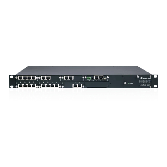
AudioCodes Mediant 1000B MSBR Hardware Installation Manual
Multi-service business router sip protocol
Hide thumbs
Also See for Mediant 1000B MSBR:
- User manual (1281 pages) ,
- Hardware installation manual (92 pages) ,
- Configuration note (52 pages)

Related Manuals for AudioCodes Mediant 1000B MSBR


Summary of Contents for AudioCodes Mediant 1000B MSBR
- Page 1 Mediant™ 1000B MSBR Multi-Service Business Router SIP Protocol Hardware Installation Manual...
-
Page 3: Table Of Contents
Connecting the FXS Lifeline Phone ................ 41 ISDN BRI Interfaces ....................43 5.5.1 Connecting to BRI Lines ..................43 5.5.2 Connecting the PSTN Fallback for BRI Lines ............44 ISDN E1/T1 Interfaces ................... 45 5.6.1 Connecting to E1/T1 Trunks ................... 45 MSBR Series Mediant 1000B MSBR... - Page 4 Mediant 1000B MSBR 5.6.2 Connecting the PSTN Fallback for E1/T1 ............... 46 Connecting the RS-232 Serial Interface to a Computer ......... 47 Connecting to Power ....................49 Hardware Maintenance ..................51 Installing and Replacing Modules ................51 6.1.1 Module Slot Assignment ..................51 6.1.2...
- Page 5 Figure A-9: Cabling OSN3 Module for Remote Desktop Connection from PC with Windows XP ..67 Figure A-10: Changing the PC's IP Address ..................68 Figure A-11: Entering IP Address in Remote Desktop Connection ............68 Figure A-12: Entering User Name and Password in Remote Desktop Connection ......68 MSBR Series Mediant 1000B MSBR...
- Page 6 Mediant 1000B MSBR List of Tables Table 3-1: Physical Dimensions ......................16 Table 3-2: Front-Panel Description ......................17 Table 3-3: FXS Module LED Description ....................18 Table 3-4: FXO Module LED Description ....................19 Table 3-5: BRI Module LED Description ....................20 Table 3-6: E1/T1 PRI TRUNKS Module LED Description ..............
-
Page 7: Weee Eu Directive
Customer Support Customer technical support and services are provided by AudioCodes or by an authorized AudioCodes Service Partner. For more information on how to buy technical support for AudioCodes products and for contact information, please visit our Web site at www.audiocodes.com/support. -
Page 8: Related Documentation
Mediant 1000B MSBR Related Documentation Manual Name SIP Release Notes Mediant 1000B MSBR SIP User's Manual MSBR Series CLI Reference Guide for System and VoIP Functionalities MSBR Series CLI Reference Guide for Data Functionality Notes and Warnings Warning: Read and adhere to all warning statements in this document before installing the device. -
Page 9: Regulatory Information
6. If trouble is experienced with this equipment, for repair or warranty information please contact AudioCodes Inc. 27 World's Fair Drive, Somerset, NJ 08873, Tel: +1-888-586-4743, Fax: +1-732-469-2298. If the equipment is causing harm to the telephone network, the telephone company may request to disconnect the equipment until the problem is resolved. -
Page 10: Document Revision Record
5. If trouble is experienced with this equipment, for repair or warranty information please contact AudioCodes Inc., 27 World's Fair Drive, Somerset, NJ 08873, Tel: +1-888-586-4743, Fax: +1-732-469-2298. If the equipment is causing harm to the telephone network, the telephone company may request to disconnect the equipment until the problem is resolved. -
Page 11: Introduction
Hardware Installation Manual 1. Introduction Introduction This document provides a hardware description of the Mediant 1000B MSBR (hereafter referred to as device) and step-by-step procedures for cabling the device. Note: For information on configuring the device, refer to the device's User’s Manual. - Page 12 Mediant 1000B MSBR Reader’s Notes Hardware Installation Manual Document #: LTRT-40881...
-
Page 13: Unpacking The Device
Four anti-slide bumpers for desktop installation • Two-meter RS-232 DB-9 adaptor cable (for direct serial connection to PC) Check, retain and process any documents. If there are any damaged or missing items, notify your AudioCodes sales representative. MSBR Series Mediant 1000B MSBR... - Page 14 Mediant 1000B MSBR Reader's Notes Hardware Installation Manual Document #: LTRT-40881...
-
Page 15: Physical Description
Fan Tray module Up to two Power Supply modules Note: Hardware configurations may change without notice. Currently available hardware configurations are listed in AudioCodes Price Book. For further enquiries, please contact your AudioCodes sales representative. MSBR Series Mediant 1000B MSBR... -
Page 16: Physical Dimensions
Mediant 1000B MSBR Physical Dimensions The device's physical dimensions are listed in the table below. Table 3-1: Physical Dimensions Item Description Enclosure 1U chassis Dimensions (H x W x D) 1U x 440 mm (17 in.) x 350 mm (14 in.) Weight Approx. -
Page 17: Front Panel Description
This slot is currently not used and is covered by a blank panel. In the next applicable release this slot is intended to host a LAN extension module (for more information, contact AudioCodes sales representative). Power 1 (Optional) Spare Power Supply module slot. -
Page 18: Fxs Module
Mediant 1000B MSBR Label/ Component Description Item # Module Schematic Extractable Fan Tray module with a schematic displayed on its front panel showing the chassis' slot numbers. The Fan Tray module cools the device's components. 3.2.1 FXS Module The FXS module provides the Foreign eXchange Subscriber (FXS) interfaces. Up to six FXS modules can be installed in the device. -
Page 19: Fxo Module
Table 3-4: FXO Module LED Description Color State Description Green Off-hooks the line toward the PBX. Blinking Detects a ring signal from the PBX. Error - malfunction in line or out of service due to Serial Peripheral Interface (SPI) failure. MSBR Series Mediant 1000B MSBR... -
Page 20: Bri Module
Mediant 1000B MSBR 3.2.3 BRI Module The BRI module provides the Integrated Services Digital Network (ISDN), Basic Rate Interface (BRI) interfaces. Up to five BRI modules can be installed in the device. Each BRI module can provide up to four BRI line interfaces and therefore, the device can support up to 20 BRI interfaces (i.e., 5 modules x 4 ports). -
Page 21: Trunks (E1/T1) Module
AIS - Alarm Indication Signal (the Blue Alarm) RAI - Remote Alarm Indication (the Yellow Alarm) Failure / disruption in the AC power supply or the power is currently not being supplied to the device through the AC power supply entry. MSBR Series Mediant 1000B MSBR... -
Page 22: Media Processing Module (Mpm)
MPM is 'General Failure', i.e., a hardware compatibility problem occurred or the DSPs cannot be identified. Contact support@audiocodes.com if you purchased the device / MPM from AudioCodes or if you're subscribed to AudioCodes Customer Technical Support (ACTS). Hardware Installation Manual Document #: LTRT-40881... -
Page 23: Crmx Module
Gigabit Ethernet (GbE) interface for connection to the Internet. • CRMX-S: 1000Base-SX optical fiber port (multi-mode fiber) • CRMX-L: 1000Base-LX optical fiber port (single-mode fiber). • CRMX-SD: Symmetric High-Speed Digital Subscriber Line (SHDSL) RJ-45 port (4 wire pairs). MSBR Series Mediant 1000B MSBR... -
Page 24: Led Description
Mediant 1000B MSBR 3.2.6.2 LED Description The LAN and WAN ports on the CRMX module provide LEDs for indicating operating status. 3.2.6.2.1 LAN LED The following table describes the LAN LED. Table 3-9: LAN LED Description Description Color State Green Ethernet link established. -
Page 25: Power Supply Module And Led Description
Table 3-12: Power Supply Module LED Description Color State Description POWER Green Power supply is operating correctly. Failure / disruption in the AC supply, or the power is currently not being supplied to the device through the AC power supply entry. MSBR Series Mediant 1000B MSBR... -
Page 26: Rear Panel Description
Notes: • The AMC chassis slots must only be installed with AMC modules that have been approved and homologated by AudioCodes. • The OSN3 module can be customer ordered with the serial port type as RJ-45 or mini USB B-type. -
Page 27: Mounting The Device
Peel off the adhesive, anti-slide rubber feet and stick one in each anti-slide groove. Flip the device over again so that it rests on its underside and place it in the required position on a desktop. MSBR Series Mediant 1000B MSBR... -
Page 28: 19-Inch Rack Mounting
Mediant 1000B MSBR 19-inch Rack Mounting The device can be installed in a standard 19-inch rack. You can mount it in the rack using any one of the following mounting options: (Recommended) Mounting the chassis on a pre-installed shelf in a 19-inch rack – see Section 4.2.1... -
Page 29: Mounting In A 19-Inch Rack Using Front Mounting Brackets
Hold the chassis in position while the second person secures the two front mounting brackets to the front posts, using 19-inch rack bolts (not supplied) to the rack posts. MSBR Series Mediant 1000B MSBR... -
Page 30: Mounting In A 19-Inch Rack Using Rear Mounting Brackets
Mediant 1000B MSBR 4.2.3 Mounting in a 19-inch Rack using Rear Mounting Brackets The device can also be mounted in a 19-inch rack, using an optional, rear-mounting bracket, in addition to the front mounting brackets. The rear mounting brackets provide extra weight support for the chassis. -
Page 31: Figure 4-2: Rear Mounting Brackets Attached To Rear Rack Posts
(three per bracket). Figure 4-3: Attaching Rear Mounting Bracket Flange to Chassis' Rear-Side Mounting Holes With two people, lift the chassis into the rack from the front of the rack. MSBR Series Mediant 1000B MSBR... -
Page 32: Figure 4-4: Sliding The Rear Mounting Flanges Into The Rear Mounting Brackets
Mediant 1000B MSBR Slide the two rear mounting bracket flanges into the slide rails of the rear mounting brackets that you previously attached to the rear posts. Figure 4-4: Sliding the Rear Mounting Flanges into the Rear Mounting Brackets Hold the chassis in position while the second person secures the rear mounting flanges to the rear mounting brackets. -
Page 33: Figure 4-6: Front Mounting Brackets Flush And Aligned With Front Rack Posts
• If the depth of the rack exceeds the maximum length of the adjustable rear mounting brackets, install an additional side rack post to accommodate the length of the rear mounting bracket. MSBR Series Mediant 1000B MSBR... - Page 34 Mediant 1000B MSBR Reader's Notes Hardware Installation Manual Document #: LTRT-40881...
-
Page 35: Cabling The Device
(located on the rear panel), using the supplied washer. Figure 5-1: Grounding the Device Connect the other end of the strap to a protective earthing. This should be in accordance with the regulations enforced in the country in which the device is installed. MSBR Series Mediant 1000B MSBR... -
Page 36: Connecting To Wan
Mediant 1000B MSBR Connecting to WAN This section describes how to connect to the WAN. The type of WAN port interface depends on the CRMX module installed in the chassis and can be one of the following: RJ-45 port (4-twisted pair copper cabling) providing 1 Gigabit Ethernet (GbE) interface (see Section 5.2.1... -
Page 37: Figure 5-4: Connecting The Sfp Fiber Optic Wan Port
Connect the LC-type plugs at the end of the fiber optic cable to the WAN port's SFP transceiver (labeled WAN). Figure 5-4: Connecting the SFP Fiber Optic WAN Port Connect the other end of the cable to the fiber network. MSBR Series Mediant 1000B MSBR... -
Page 38: Shdsl Wan Cabling
Mediant 1000B MSBR 5.2.3 SHDSL WAN Cabling The CRMX-SD module provides a WAN connection through an SHDSL interface port. The SHDSL port has four wire-pairs, supporting up to four SHDSL ports on a single physical RJ-45 connector. The specifications of the SHDSL interface are listed below: ... -
Page 39: Connecting To Lan
Using a straight-through RJ-45 Ethernet Cat 6 or Cat 5e (two-pair Category 5 UTP) cable, connect the CRMX module's LAN port/s (labeled I, II, and III) to the LAN. Figure 5-7: Connecting to LAN Ports Connect the other end of the cable to the network. MSBR Series Mediant 1000B MSBR... -
Page 40: Connecting To Analog Devices
Mediant 1000B MSBR Connecting to Analog Devices This section describes the cabling procedures for analog interfaces. 5.4.1 Connecting to FXS Interfaces The procedure below describes how to connect to FXS interfaces such as fax machines, modems, and plain old telephone system (POTS) telephones. -
Page 41: Connecting To Fxo Interfaces
An analog Lifeline can be setup for each FXS module installed in the chassis. • The scenarios (i.e., power outage and/or IP network loss) upon which Lifeline is triggered is configured by the LifeLineType parameter. For more information, see the User's Manual. MSBR Series Mediant 1000B MSBR... -
Page 42: Figure 5-10: Rj-11 Connector Pinouts For Analog Lifeline
Mediant 1000B MSBR The analog Lifeline is provided only by Port I on an FXS module. This port connects to the POTS phone and the PSTN or PBX, using a splitter cable. The splitter cable connects pins 1 and 4 to another source of an FXS port, and pins 2 and 3 to the POTS phone, as shown... -
Page 43: Isdn Bri Interfaces
When configured as NT, the BRI port drives a nominal voltage of 38 V with limited current supply of up to 100 mA. The voltage is of Power Source 1 type (line voltage). Power Source 2 is optional. MSBR Series Mediant 1000B MSBR... -
Page 44: Connecting The Pstn Fallback For Bri Lines
Mediant 1000B MSBR 5.5.2 Connecting the PSTN Fallback for BRI Lines The device supports a PSTN Fallback feature for BRI lines, whereby if a power outage or IP connectivity problem (e.g., no ping) occurs, IP calls are re-routed to the PSTN. This guarantees call continuity. -
Page 45: Isdn E1/T1 Interfaces
To connect to E1/T1l trunks: Connect the E1/T1 trunk cables to the ports on the device's TRUNKS module(s). Figure 5-16: Cabling E1/T1 Trunk Ports Connect the other end of the trunk cables to a PBX/PSTN switch. MSBR Series Mediant 1000B MSBR... -
Page 46: Connecting The Pstn Fallback For E1/T1
Mediant 1000B MSBR 5.6.2 Connecting the PSTN Fallback for E1/T1 The device supports a PSTN Fallback feature, whereby upon a power outage or IP connectivity problem (e.g., no ping), IP calls are re-routed to the PSTN. This guarantees call continuity. -
Page 47: Connecting The Rs-232 Serial Interface To A Computer
Connector Pinouts: Refer to pinouts shown in orderable RS-232 cable adaptor below. You can purchase an RS-232 cable adapter (9-pin DB to flat connector) from AudioCodes, using the Product Number (P/N) PicoBlade-Serial. This orderable item is supplied in a kit of 10 cables. -
Page 48: Figure 19: Serial Connection With Pc For Cli Communication
Mediant 1000B MSBR Note: Orderable RS-232 cable adapter: • Conductive 30 (7/0.1)x3C, Tinned copper wire. PVC Coating dia=0.7mm, Color black. Shield: AL (MAYLER)+BRAID (16/4/0.12) Tinned copper wire, coverage 90% min. Assembly cotton paper. Jacket PU (4485AF), dia=3.5mm. • Conductive 30 (7/0.1)x6C, Tinned copper wire. PVC Coating dia=0.6mm, Color black. -
Page 49: Connecting To Power
Units must be connected (by service personnel) to a socket-outlet with a protective earthing connection. • Use only the AC power cord supplied with the device. ご注 意 本製品に添付の電源ケーブルは、Mediant 1000B MSBR に専用設計されているため、汎 用性がありません. 本電源ケーブルを他の機器に使用されないよう、ご注意ください. Notes: • You can install up to two Power Supply modules (Power 1 and Power 2), each providing an AC power connector on the device's rear panel. -
Page 50: Figure 20: Connecting To Power
Mediant 1000B MSBR To connect the device to the power supply: On the device's rear panel, connect the left (active) 100-240V~50-60 Hz power socket to a standard electrical outlet using the supplied AC power cord. Figure 20: Connecting to Power When the device receives powers, the POWER LED on the front panel of the Power Supply module is lit green. -
Page 51: Hardware Maintenance
3 (no skipping of slots). It is recommended to assign the TRUNKS, BRI, FXS, and FXO modules to the slots (starting from Slot 1) according to the order of priority listed below: TRUNKS FXS and/or FXO MSBR Series Mediant 1000B MSBR... -
Page 52: Removing Kapton Tape Before Installing Modules
Mediant 1000B MSBR For example, if the device requires one TRUNKS module and two FXS modules, then you must insert the TRUNKS module in Slot 1 and the two FXS modules in slots 2 and 3 respectively. If at a later stage, you wish to add a BRI module (for example), then you must replace the FXS module in Slot 2 with the new BRI module, and then re- insert this replaced FXS module in Slot 4. -
Page 53: Special Instructions For Installing The Power Supply Module
This module orientation is considered as facing down. Push the module into the slot and press on it firmly to ensure it has been fully inserted. MSBR Series Mediant 1000B MSBR... -
Page 54: Installing And Removing Amc-Based Modules On The Rear Panel
Mediant 1000B MSBR Using a flathead screwdriver, tighten the module's mounting pins. Power on the device. 6.1.5 Installing and Removing AMC-Based Modules on the Rear Panel The OSN3 modules are hot-swappable and can be installed and removed without disrupting other non-related OSN3 services running on the device. If two HDMX modules are used and you need to replace or remove one, you can also do this without affecting OSN3 functionality. -
Page 55: Replacing I/O Modules On The Front-Panel Slots
Note: For replacing the CRMX module, no software procedure is required (i.e., ignore steps 2 and 7 in the procedure below). MSBR Series Mediant 1000B MSBR... -
Page 56: Figure 6-6: Module Orientation In Top And Bottom Chassis Slots
Mediant 1000B MSBR To replace I/O modules: If you are replacing the CRMX module, power down the device, and then skip to Step 3. Software-remove the module, using the device's Web interface's 'Home' page (refer to the device's User's Manual). -
Page 57: A Open Solution Network Server Platform
The OSN is based on single and mid-sized Advanced Mezzanine Card / AMC (AdvancedMC form-factor) modules. These are housed in the chassis' AMC slots on the rear panel. OSN Server Offerings The table below lists available OSN server platforms that can be ordered from AudioCodes. Table A-1: OSN Server Platforms Memory Storage... -
Page 58: Osn3 Module
Mediant 1000B MSBR A.2.1 OSN3 Module The OSN3 module is part of the OSN3 server platform. This module provides the port connector interfaces and is housed in Slot #2 on the rear panel. Ports Description A.2.1.1 The OSN3 module is shown below and described in the subsequent table. -
Page 59: Leds Description
The OSN3 module LEDs are shown in the figure below and described in the subsequent table. Figure A-3: OSN3 Module LEDs Table A-5: OSN3 Module LEDs Description Item Label Color State Description Green Flashing Hardware normal operation Hardware fault (over-temperature or excess MSBR Series Mediant 1000B MSBR... - Page 60 Mediant 1000B MSBR Item Label Color State Description voltage feed). When lit during boot-up, indicates power failure. Flashing Processor over-temperature above 100°C. If LEDs 0, 1, and 2 are also flashing, there is a processor over-temperature above 125°C and as a result, the module shuts down.
-
Page 61: Osn4 Module
10Base-T, 100Base-TX and 1000Base-T data transmission (Auto- Negotiation). Auto-wire switching for crossed cables is also supported (Auto-MDI/X). HDMI HDMI port for connecting to a graphic display monitor. Console (serial) port (micro-USB) for serial interface (COM1). MSBR Series Mediant 1000B MSBR... -
Page 62: Leds Description
Mediant 1000B MSBR The RJ-45 connector pinouts for the Gigabit Ethernet interface are listed in the table below: Table A-7: RJ-45 Connector Pinouts for Gigabit Ethernet Interface 100Base-Tx 1000Base-T Signal Signal Function BI_DA+ BI_DA- BI_DB+ BI_DC+ BI_DC- BI_DB- BI_DD+ BI_DD- LEDs Description A.2.2.2... -
Page 63: Hdmx Module
The HDMX module is housed in Slot #1 on the rear panel. Notes: • For additional storage capacity per HDMX module, contact your AudioCodes sales representative. • The OSN platform can optionally, be ordered with dual hard-disk drives (two HDMX modules). -
Page 64: Installing An Operating System On The Osn Server
Mediant 1000B MSBR Item # Label Color State Description Blue Module can be extracted from chassis slot once dismounted from the OSN operating system. Module correctly inserted in chassis slot Hard disk drive in use (active). Hard disk drive not in use. -
Page 65: Installing Linux On Osn4
Figure A-8: Cabling OSN4 Module for Installing Linux Power up the device; the OSN server boots up from the USB storage device and the Linux installation begins. Follow the Linux online installation instructions to install the Linux operating system. MSBR Series Mediant 1000B MSBR... -
Page 66: Connecting Remotely To Osn3 Using Windows
Mediant 1000B MSBR Connecting Remotely to OSN3 using Windows You can connect to the OSN3 server using Microsoft's Remote Desktop Connection program. Notes: • To connect remotely to the OSN3 server running Windows, make sure that Remote Desktop is enabled. -
Page 67: Connecting Through Remote Desktop
Figure A-9: Cabling OSN3 Module for Remote Desktop Connection from PC with Windows XP Change the PC's IP address so that it is in the same subnet as the default OSN3 server's IP address (i.e., 10.1.10.12). The figure below displays an example of changing a PC's IP address: MSBR Series Mediant 1000B MSBR... -
Page 68: Figure A-10: Changing The Pc's Ip Address
Mediant 1000B MSBR Figure A-10: Changing the PC's IP Address Start Microsoft's Remote Desktop Connection program - from the Start menu, point to Programs, to Accessories, to Communications, and then click Remote Desktop Connection. Figure A-11: Entering IP Address in Remote Desktop Connection In the 'Computer' field, enter the OSN server's default IP address (i.e., 10.1.10.12). -
Page 69: B Module Hardware Revision Compatibility
CRMX-L (LAN 1, 2, 3, GE WAN 1000Base-LX) P1.5 FASU00556 CRMX-C (LAN 1, 2, 3, GE WAN copper Ethernet) FASU00557 CRMX-S (LAN 1, 2, 3, GE WAN 1000Base-SX) P1.5 FASU00636 CRMX-SD (LAN 1, 2, 3, SHDSL WAN) No Revision Constraint MSBR Series Mediant 1000B MSBR... - Page 70 Hardware Installation Manual www.audiocodes.com...