Denon DN-S700 Service Manual
Table top single cd/mp3 player
Hide thumbs
Also See for DN-S700:
- Owner's manual (21 pages) ,
- Features & specifications (2 pages) ,
- Owner's manual (21 pages)
Table of Contents
Advertisement
Quick Links
Download this manual
See also:
Owner's Manual
Ver. 1
SERVICE MANUAL
MODEL
JP
E3
E2
EK
E2A E2C E1K EUT
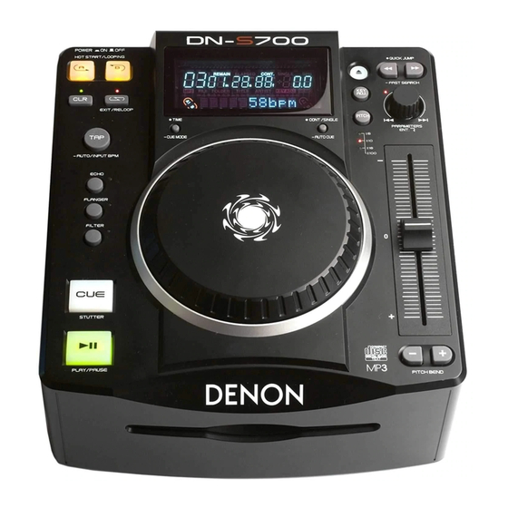
DN-S700
TABLE TOP SINGLE CD/MP3 PLAYER
For purposes of improvement, specifications and design are subject to change without notice.
●
Please use this service manual with referring to the operating instructions without fail.
●
Some illustrations using in this service manual are slightly different from the actual set.
●
PROFESSIONAL BUSINESS COMPANY
X0457 V.01 DE/CDM 0909
Advertisement
Table of Contents

Related Manuals for Denon DN-S700


Summary of Contents for Denon DN-S700
- Page 1 Ver. 1 SERVICE MANUAL MODEL E2A E2C E1K EUT DN-S700 TABLE TOP SINGLE CD/MP3 PLAYER For purposes of improvement, specifications and design are subject to change without notice. ● Please use this service manual with referring to the operating instructions without fail.
-
Page 2: Safety Precautions
Care is also taken with the positions of the wores omsode amd clamps or other dangerous situations. are used to keep wires away from heating and high voltage parts, so be sure to set everything back as it was originally. DN-S700... - Page 3 DIMENSION 215 m m DN-S700...
- Page 4 Otherwise, incorrect arrangement can be a cause of noise generation. AC power cord Flat cable on the switch Wires bended inside, not outside the cabinet Bending line Put 2P wires into the WIRE MOUNT DN-S700...
- Page 5 • Photographs for which no direction is indicated were taken from above the product. The viewpoint of each photograph Direction of photograph: B (Photografy direction) [View from above] Direction of photograph: D Direction of photograph: C Front side Direction of photograph: A DN-S700...
- Page 6 Direction of photograph: B Direction of photograph: C Direction of photograph: D (2) Disconnect the connector wires and FFC cable. FFC cable Direction of photograph: A <Attention of assembling> Rearrange the wiring of the wire. Refer to the WIRE ARRANGEMENT (4 page). DN-S700...
- Page 7 2. SWITCHING POWER → → Proceeding : TOP / BOTTOM SWITCHING POWER (1) Remove the screws, then detach the ISOLATION COVER ASS'Y. Direction of photograph: B ISOLATION COVER ASS'Y (2) Remove the screws SWITCHING POWER Direction of photograph: B SPACER SUPPORT DN-S700...
- Page 8 (1) Pull up the KNOB, then remove the NUT. KNOB (2) Remove the screws, then detach the ISOLATION COVER ASS'Y. Direction of photograph: B ISOLATION COVER ASS'Y (3) Disconnect the FFC cable, then remove the screws. CD DOOR FRAME ASS'Y Direction of photograph: B FFC cable DN-S700...
- Page 9 (1) Detach the KNOB, then remove the E RING.. KNOB E RING Direction of photograph: B KNOB 5. TURNTABLE FRAME → → Proceeding : TOP / BOTTOM VFD/CONTROL PCB ASS'Y → TURNTABLE ASS'Y → TURNTABLE FRAME (1) Remove the screws. Direction of photograph: B DN-S700...
- Page 10 FFC cable CN11 FFC cable CN102 7. MAIN PCB ASS'Y → → Proceeding : TOP / BOTTOM BOTTOM SLOT-IN FEEDER MECHA ASS'Y → MAIN PCB ASS'Y Please refer to "EXPLODED VIEW" for the disassembly method of MAIN PCB ASS’Y. DN-S700...
-
Page 11: Service Mode
1. Contents of Service Program Turn on the power while pressing both B button and the PARAMETER knob to set the service mode of DN-S700. The various check items can be selected with the PARAMETER knob, the various test items can be selected with the A, B, EXIT /RELOOP and BEND buttons. -
Page 12: Test Mode
Unable to close the disc holder in the regular time E4 01 Unable to open the disc holder in the regular time E5 00 The inner SW dose not turn on E5 01 Slider error E5 02 The inner SW dose not turn off DN-S700... - Page 13 E **** Error code 4. µcom update With the DN-S700, the servo μcom, system μcom and DSP can be updated from a disc. (1) Creating the update disc Use the procedure described below to create the disc for updating the servo system microprocessor and DSP.
- Page 14 TROUBLE SHOOTING DN-S700...
- Page 15 DN-S700...
-
Page 16: Table Of Contents
SENS BIAS SCLK ATSK RFACI WFCK RFACO XUGF XPCK C2PO SCOR EQ_IN AC_SUM WDCK PDSENS COUT RFDCO 9 10 11 12 13 14 15 16 17 18 19 20 21 22 23 24 25 26 27 28 29 30 DN-S700... -
Page 17: Lmut
Sequencer Digital DOUT Digital PCMD Selector Interface LRCK Error Corrector XRST TES1 TEST Demodulator 0 to 5 Sub Code 0 to 5 Processor 0 to 2 RFamp Block 0 to 2 Asymmetry Digital DC/DC Corrector Converter – 2 – DN-S700... - Page 18 3.3V C signal input. D signal input. — — — — Analog power supply. RFDC signal output. RFDCO RFDC signal input to DSSP block by command switch. PDSENS Reference voltage pin for PD. AC_SUM Analog RFAC summing amplifier output. DN-S700...
- Page 19 1, 0 D/A interface bit clock output. — — Internal digital power supply. EMPH 1, 0 High when the playback disc has emphasis, low it has not. EMPHI High when de-emphasis is ON, low when input OFF. – 5 – DN-S700...
-
Page 20: Xtsl
SBSO readout clock input. XRST System reset. Reset when low. SYSM Mute input. Muted when high. DATA Serial data input from CPU. — — Internal digital GND. XLAT Latch input from CPU. The serial data is latched at the falling edge. DN-S700... - Page 21 • FSTO is the 2/3 frequency-division output of the XTAI pin. • SOUT is the serial data output inside the servo block. • SOCK is the serial data readout clock output inside the servo block. • XOLT is the serial data latch output inside the servo block. BA6392FP (IC102) DN-S700...
- Page 22 DN-S700...
- Page 23 BA6392FP Pin discription DN-S700...
- Page 24 3) Correct the position of input cable 3) Improper setup of input cable and switch correctly Connection and switch Loose cable connections Firmly connect all audio plugs Line / Phono switch reversed Poor power plug connection Connection the input cable correctly DN-S700...
- Page 25 IC DATA IN /CSAD IC DATA IN VREFH AD5V VREFL ADGND BKGD XTAL XTAL PC1A' LINE2 FADER CONTROL OUTPUT PC1B' LINE2 FADER CONTROL OUTPUT PC2A' LINE4 FADER CONTROL OUTPUT PC2B' LINE4 FADER CONTROL OUTPUT PC3A' LINE6 FADER CONTROL OUTPUT DN-S700...
- Page 26 Mode Control, BCK/De-emphasis Selection 2 ML/I Mode Control, WDCK/Input Format Selection NOTES: (1) Pins 1, 2, 3; Schmitt Trigger input. (2) Pins 22, 24, 25, 26, 27, 28; Schmitt Trigger input with pull-up resister. (3) Pin 23; Schmitt Trigger input with pull-down resister. DN-S700...
- Page 27 74AHC595DR (IC203, 204) RCLK SRCLK SRCLR H′ LC75710NE (IC205) DN-S700...
- Page 28 PLLCR(11) static chip select 0 SDRAM address / static adr SDRAM address / static adr SDRAM address / static adr SDRAM address / static adr SDRAM address / static adr SDRAM address / static adr BCLK/GPIO10 sdram clock output DN-S700...
- Page 29 1 enable DATA31 data CORE-VDD CORE-VDD SDRAM address / static adr CORE-GND CORE-GND SDRAM address / static adr SDRAM address / static adr SDRAM address / static adr SDRAM address / static adr PAD-VDD PAD-VDD SDRAM address / static adr DN-S700...
- Page 30 QSPI chip select 2 DATA20 data DATA22 data DATA18 data DATA23 data DATA17 data PADD-VDD PAD-VDD DATA16 data CFLG/GPIO18 CFLG input EBUOUT1/GPO36 audio interfaces EBU out 1 CORE-GND CORE-GND EBUIN3/ADIN0/GPI38 audio interfaces EBU in 3 / AD convertor input0 DN-S700...
- Page 31 1 SCLK4/GPIO50 audio interfaces serial clock 4 TA/GPIO20 Transfer acknowledge SDATAI1 audio interfaces serial data in 1 EBUIN1/GPI36 audio interfaces EBU in 1 PLLGRDVDD PLLGRDVDD PLLGRDGND PLLGRDGND PLLPADGND PLLPADGND PLLPADVDD PLLPADVDD PLLCOREGND PLLCOREGND PLLCOREVDD PLLCOREVDD DN-S700...
- Page 32 Bus write enable TMS/BKPT JTAG/debug CORE-GND CORE-GND JTAG PAD-GND PAD-GND PST3/GPIO62 debug CNPSTCLK/GPO63 debug PST1/GPIO60 debug PAD-VDD PAD-VDD PST2/GPIO61 debug PST0/GPIO59 debug TDI/DSI jtag/debug TEST0 test TIN0/GPI33 timer input 0 HI-Z jtag DDATA3/GPIO4 debug TOUT0/GPO33 timer output 0 DDATA1/GPIO1 debug DN-S700...
- Page 33 1 CORE-GND CORE-GND SDRAM address / static adr TIN1/GPIO23 Timer input 1 address address PAD-GND PAD-GND address address address address address CORE-VDD CORE-VDD address SCF5249 Integrated ColdFire® Microprocessor Data Sheet, Rev. 3 Freescale Semiconductor TEST1 test PAD-VDD PAD-VDD DN-S700...
- Page 34 Power and ground for the input buffers and the core logic. Isolated power supply and ground for the output buffers to provide improved noise Data output power/ground immunity. No connection N.C/RFU This pin is recommended to be left No Connection on the device. /reserved for future use DN-S700...
- Page 35 K4S641632D Block diagram Data Input Register LDQM Bank Select 1M x 16 1M x 16 1M x 16 1M x 16 Column Decoder Latency & Burst Length LCKE Programming Register LRAS LCBR LCAS LWCBR LDQM Timing Register L(U)DQM M29W800DB (U3) DN-S700...
- Page 36 XC9536-10-VQ44C (U8) DN-S700...
-
Page 37: Block Diagram
74HC04 FOCUS TRACK ING AUDI O OUT MCF 5249 CXD3059 PCM1716 CD DSP MC9S08AW32 SERVO CPU SWI TCHES XC9536 74HCU04 BA6218 CPLD CL OCK DRI VER LOADI NG POWER SW. SWI TCHI NG POWER AC IN SUPPLY -32V AC3.5V DN-S700... - Page 38 PRINTED WIRING BOARDS MAIN PCB UNIT (1/2) COMPONENT SIDE DN-S700...
- Page 39 MAIN PCB UNIT (2/2) FOIL SIDE DN-S700...
- Page 40 CONTROL PCB UNIT (1/2) COMPONENT SIDE DN-S700...
- Page 41 CONTROL PCB UNIT (2/2) FOIL SIDE DN-S700...
- Page 42 VFD PCB UNIT COMPONENT SIDE FOIL SIDE MOTOR PCB UNIT SW PCB UNIT COMPONENT SIDE DN-S700...
-
Page 43: Note For Parts List
Indicates number of zeros after efective number. (0 or 1) (More than 2) 2-digit effective number. 2-digit effective number. ・ Units:pF ・ Units:pF ・ When the dielectric strength is indicated in AC,"AC" is included after the dieelectric strength value. DN-S700... - Page 44 R26,27 CHIP RESISTOR(10K OHM,1/10W,0603,J,TP ,50V) 412-CDVD2001-534 CHIP RESISTOR(270 OHM,1/10W,0603,J,TP ,50V) 412-007USB-698 R30,31 CHIP RESISTOR(0 OHM,1/10W, 0603,J,TP,50V) 412-CDVD2001-552 CHIP RESISTOR(470 OHM,1/10W, 0603,J,TP,50V) 412-CDVD2001-545 R101 CHIP RESISTOR(22 OHM,1/10W,0603,F,TP ,50V) 412-CDVD2001-554 R102 CHIP RESISTOR(11KOHM,1/10W,J,TP 0603,50V) 412-900-1012 R103 CHIP RESISTOR470K OHM,1/10W, 0603,J,TP,50V) 412-007USB-707 DN-S700...
- Page 45 412-DJ1-420 (10K OHM,1/8W J,RA TYPE,7R8P) CAPACITORS GROUP C001 AC SAFETY CAPACITOR(0.01uF/250V,M,BULK,Y5V) 413-S250-747 C01-14, CHIP CAPACITOR(0.1uF/50V,Z,0603 TYPE,Y5V) 413-DCM280-773 C16,C17 CHIP CAPACITOR(15pF/50V,J,0603 TYPE,NPO) 413-007USB-781 C18-23 CHIP CAPACITOR(0.1uF/50V,Z,0603 TYPE,Y5V) 413-DCM280-773 CHIP CAPACITOR(0.1uF/50V,Z,0603 TYPE,Y5V) 413-DCM280-773 00D9587054907 ELEC. CAPACITOR 413-HMA2200-5017 (100uF/10V,M,105 ℃ ,TAPING 5*7,MINI) DN-S700...
- Page 46 413-DCM280-773 C156 00D9587054907 ELEC. CAPACITOR 413-HMA2200-5017 (100uF/10V,M,105 ℃ ,TAPING 5*7,MINI) C157 CHIP CAPACITOR( 220pF/50V,0603,TYPE NPO) 413-007USB-787 C159 CHIP CAPACITOR(0.1uF/50V,Z,0603 TYPE,Y5V) 413-DCM280-773 C160 00D9587054907 ELEC. CAPACITOR 413-HMA2200-5017 (100uF/10V,M,105 ℃ ,TAPING 5*7,MINI) C161 00D9587056303 ELEC. CAPACITOR 413-SPPW3-235 (10uF/25V,M,105 ℃ ,TAPING 4*7,MINI) DN-S700...
- Page 47 941115001080S INDUCTOR(10uH,AL0204ST-100K-S-A,TAPING) 415-HMD5000-097 L107 00D9580016900 BEAD CORE(TB36-863445NP T-26mm) 415-HV3500K-090 L108 941119001530S INDUCTOR(100MH J 0707-444-W077) 415-HT8015-040 L109 90M-FC900450R BEAD(RH03506BT-B-N,TAPING RT) 415-DCM370E3-134 L110 90M-FC900450R BEAD(RH03506BT-B-N,TAPING RT) 415-DCM370E3-134 L111 90M-FC900450R BEAD(RH03506BT-B-N,TAPING RT) 415-DCM370E3-134 L112 00D9580016900 BEAD CORE(TB36-863445NP T-26mm) 415-HV3500K-090 L113 941115001080S INDUCTOR(10uH,AL0204ST-100K-S-A,TAPING) 415-HMD5000-097 DN-S700...
- Page 48 413-007USB-783 C220 941134002020S ELEC. CAPACITOR(10uF/35V,M,TAPING 4*7,MINI) 413-810-919 C221 CHIP CAPACITOR(0.01uF/50V,K,0603 TYPE,X7R) 413-DCM280-771 C223 00D9587054907 ELEC. CAPACITOR 413-HMA2200-5017 (100uF/10V,M,105 ,TAPING 5*7,MINI) OTHER PARTS GROUP CN201B 00D9587049608 9P FFC CONNECTOR(90°) 404-900-2092 VFD201 00D3938076006 VFD(86*40*9mm) 410-S700-360 VFD BRACKET 100-700-2674 VFD SHEET 612-700-327 DN-S700...
- Page 49 R258,259 CHIP RESISTOR(560 OHM,1/10W,0603,J,TP ,50V) 412-CDVD2001-549 R260,261 CHIP RESISTOR(470 OHM,1/10W, 0603,J,TP,50V) 412-CDVD2001-545 R262,263 CHIP RESISTOR(470 OHM,1/10W, 0603,J,TP,50V) 412-CDVD2001-545 CAPACITORS GROUP C201 00D9587054907 ELEC. CAPACITOR 413-HMA2200-5017 (100uF/10V,M,105 ℃ ,TAPING 5*7,MINI) C202-204 CHIP CAPACITOR(0.1uF/50V,Z,0603 TYPE,Y5V) 413-DCM280-773 C205,206 CHIP CAPACITOR(22pF/50V,J,0603 TYPE,NPO) 413-CR701-5161 DN-S700...
- Page 50 SCREW(WPTP,2.6*8,C-1018,É’6.5) 602-4-559 VR CUSHION(0.5t,BLACK) 612-HDJ9700-015 SW PCB ASS'Y Ref. No. Part No. Part Name Remarks Q'ty New OTHER PARTS GROUP 941662001930S LEAF SW 403-MK9-259 SW2,3 941662001920S LEAF SW 403-MK9-258 941662001930S LEAF SW 403-MK9-259 941644001900S 5P 1.0 FFC SOCKET(52271-0579,SMD90°) 404-MK11-3155 DN-S700...
- Page 51 ---MEMO--- DN-S700...
- Page 52 EXPLODED VIEW WARNING: Parts marked with this symbol have critical characteristics. Use ONLY replacement parts recommended by the manufacturer. DN-S700...
- Page 53 25 941411001710D KNOB 604-700-502 26 941411001720D KNOB 604-700-503 27 941411001730D 2 KEY KNOB 604-700-504 28 941412001740D CIRCULAR KNOB 604-700-505 606-F200-003 PULLEY WASHER(φ11.6*76*0.25t) 606-B300-039 WASHER(φ5.5*3*0.7t) E RING 606-DJ3000-105 606-Q2221-122 WASHER(φ8*3.2*1t,NI) 33 00D9587045107 FOOT(PORON,BLACK,φ15*3t) 612-HV3500K-055 PROTECTIONMAT 612-700-326 CUSHION 612-700-328 SCREW(3*5 P=0.5) 602-B300-041 DN-S700...
- Page 54 MECHA TO CN11 404-S700-3231 6P 2.0 CONNECTOR WIRE MECHA TO CN102 404-S700-3233 51 941606001850S FFC CABLE(16P 1.0 L=150+/-) CN06A TO CN06B 406-S700-1096 52 941606001860S FFC CABLE(5P 1.0 L=115 ,+/-) MECHA TO CN03 406-S700-1097 3N2P CONNECTOR WIRE CN02 TO CN1 404-S700-3234 DN-S700...
- Page 55 5-1 941541001450P INSTRUCTION MANUAL ((DNS700E2/E3) 502-DS700E2-2778 SERVICE SHEET(515-0996-001) 502-300E2-1771A WARRANTY CARD(515-0966-206) 502-100E3-1772A 5-4 00D9580039505 PE BAG(240*340mm) 505-DJ2500H-014 6 941531001770D GIFT BOX 507-700-3091 SHIPPING LABEL(86*137mm,t=0.1mm) 701-DS700E2-3655 SHIPPING LABEL(86*137mm,t=0.1mm) 701-DS700E3-3655 POLYBAG((PE-HD,150*300mm,t=0.04mm) 505-BJ1900AC-093 10 941533001800D POLYFOAM C 506-700-574 11 941537001820D PASTEBOARD 507-700-3130 DN-S700...
-
Page 56: Wiring Diagram
WIRING DIAGRAM CONTROL PCB SWITCHING POWER CN201A CN06B CONTROL PCB CN201A TO VFD PCB CN201B AC POWER CORD CN101 CN06A CN01 MAIN PCB CN102 CN03 CN11 DN-S700... - Page 57 ---MEMO--- DN-S700...
- Page 58 NOTICE: ALL RESISTANCE VALUES IN OHM. k=1,000 OHM M=1,000,000 OHM ALL CAPACITANCE VALUES IN MICRO FARAD. P=MICRO-MICRO FARAD EACH VOLTAGE AND CURRENT ARE MEASURED AT NO SIGNAL INPUT CONDITION. CIRCUIT AND PARTS ARE SUBJECT TO CHANGE WITHOUT PRIOR NOTICE. DN-S700...
-
Page 59: Xrst
22/16 C184 100/10 C103 Q302 L101 C122 R174 C118 C121 C123 D104 100/10 C1815 22/16 3.3V 1SS132 L103 1000P Q101 C110 A933 R105 R102 R108 100K 3.3K 3.3V-3 R103 C115 C119 100P 470K 1500P SCHEMATIC DIAGRAMS (1/4) SERVO UNIT DN-S700... -
Page 60: Data
LRCK2 GPO55 XC9536-10-VQ44 GPO55 VCC3.3V K4S641632D ACKB ACKB ACKS ACKS SCOR SCOR XRST 1.8V D3.3V BA18C0FP /WLA D3.3V 3.3V D3.3V GPO55 /CS1 220/10 100/10 D3.3V DOUT CN04 JTAG 74HC14 /WLB /WLA SCHEMATIC DIAGRAMS (2/4) 470P SERVO (DSP) UNIT 470P DN-S700... - Page 61 405-S700-2455 CN201B CN201A VRST VFDCE VFD201 R206 VFDCL VFD DN-S700 VFDDI C212 DGND -32V IC202 IC203 IC204 C214 74595 74595 C211 R212 R213 AT93C46 /URST CN203 IC205 R210 R261 R262 R263 C205 L201 VFDDI 10uH VFDCL X201 D203 D204 D205...
- Page 62 SW04 SW03 CN01 MOTOR CN901 SW02 CON5 SW01 SWITCH UNIT MOTOR UNIT SCHEMATIC DIAGRAMS (4/4) SWITCH UNIT MOTOR UNIT DN-S700...