Advertisement
Owner's Manual & Safety Instructions
Save This Manual
operating, inspection, maintenance and cleaning procedures. Write the product's serial number in the
back of the manual near the assembly diagram (or month and year of purchase if product has no number).
Keep this manual and the receipt in a safe and dry place for future reference.
When unpacking, make sure that the product is intact
and undamaged. If any parts are missing or broken,
please call 1-888-866-5797 as soon as possible.
©
Copyright
2016 by Harbor Freight Tools
No portion of this manual or any artwork contained herein may be reproduced in
any shape or form without the express written consent of Harbor Freight Tools.
Diagrams within this manual may not be drawn proportionally. Due to continuing
improvements, actual product may differ slightly from the product described herein.
Tools required for assembly and service may not be included.
Keep this manual for the safety warnings and precautions, assembly,
Visit our website at: http://www.harborfreight.com
Email our technical support at: productsupport@harborfreight.com
®
. All rights reserved.
Read this material before using this product.
Failure to do so can result in serious injury.
SAVE THIS MANUAL.
18a
Advertisement

Related Manuals for Central Machinery 63469


Summary of Contents for Central Machinery 63469
- Page 1 Owner’s Manual & Safety Instructions Save This Manual Keep this manual for the safety warnings and precautions, assembly, operating, inspection, maintenance and cleaning procedures. Write the product’s serial number in the back of the manual near the assembly diagram (or month and year of purchase if product has no number). Keep this manual and the receipt in a safe and dry place for future reference.
-
Page 2: Table Of Contents
Indicates a hazardous situation which, if not avoided, could result in death or serious injury. Indicates a hazardous situation which, if not avoided, could result in minor or moderate injury. Addresses practices not related to personal injury. Page 2 For technical questions, please call 1-888-866-5797. Item 63469... -
Page 3: Safety
The smaller the gauge number, the heavier the cord. 20. NEVER LEAVE TOOL RUNNING UNATTENDED. TURN POWER OFF. Don’t leave tool until it comes to a complete stop. Item 63469 For technical questions, please call 1-888-866-5797. Page 3... - Page 4 250 VAc 3-prong plug and Outlet. The tool has a grounding plug that looks like the plug illustrated above in 250 VAc 3-prong plug and Outlet. Make sure the tool is connected to an outlet Page 4 For technical questions, please call 1-888-866-5797. Item 63469...
- Page 5 It must be understood by the operator that changing the Saw Blade. common sense and caution are factors which cannot be built into this product, but must be supplied by the operator. Item 63469 For technical questions, please call 1-888-866-5797. Page 5...
-
Page 6: Specifications
90 / 135 / 195 / 255 FPM 7″ Round Stock Cutting Capacity 7″ x 12″ Rectangular Stock V-Belt Type 3V-270 Blade Size 93″ L x .75″ W x 0.031″ Thick / 6 TPI Page 6 For technical questions, please call 1-888-866-5797. Item 63469... -
Page 7: Setup
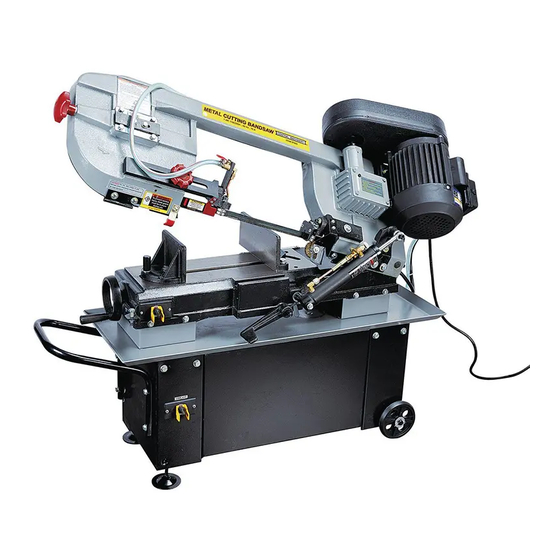
(92-3) through the hole in each end of the should attempt to rewire the Bandsaw. Wheel Rod. Make sure to bend the Cotter Pins to secure the Wheels in place. (See Figure B.) Item 63469 For technical questions, please call 1-888-866-5797. Page 7... - Page 8 Functions ADJUSTABLE cOOLANT BLADE GUIDE VALVE KNOB BLADE TENSIONER BLADE MOVEABLE VISE pLATE VISE HAND FEED WHEEL cyLINDER cONTROLS pOWER SWITcH cOOLANT pUMp SWITcH Page 8 For technical questions, please call 1-888-866-5797. Item 63469...
-
Page 9: Operation
Saw Blade will result. 6. Tighten the new Saw Blade by turning the Blade Tension Knob in a clockwise direction. 7. Close the Blade Back Cover. Item 63469 For technical questions, please call 1-888-866-5797. Page 9... - Page 10 4. Position the Guide Pivot Assembly by turning it to the desired position of clearance. Then re-tighten the Hex Head Socket Screw. 5. Adjust the second Blade Guide Bearing in the same manner. Page 10 For technical questions, please call 1-888-866-5797. Item 63469...
- Page 11 V-Belt Tension Limiter Bolt (301). HEX NUTS NOT SHOWN) 5. Turn the V-Belt Tension Limiter Bolt against the Motor Mount Bracket (307) and tighten the Nut (302). MOTOR MOUNT pLATE Figure G Item 63469 For technical questions, please call 1-888-866-5797. Page 11...
- Page 12 3. Guide the Saw Blade (251) through the slot in the Vertical Table (55-2), and secure it in position with the two Screws. (See Figure K.) Figure I VERTIcAL TABLE ScREWS Figure K Page 12 For technical questions, please call 1-888-866-5797. Item 63469...
- Page 13 Excessive feed pressure can break the Saw Blade. Insufficient feed pressure dulls the Saw Blade rapidly. 3. The Feed Lock locks or unlocks Cylinder movement entirely. Figure L Item 63469 For technical questions, please call 1-888-866-5797. Page 13...
- Page 14 12″ workpiece: • Remove both fasteners from the Rear Vise Jaw. • Position (B) over the outer threaded hole on the Base. Page 14 For technical questions, please call 1-888-866-5797. Item 63469...
- Page 15 2. The Blade Guide Bracket should be set BLADE GUIDE KNOB as close as possible to the workpiece, without interfering with the workpiece. 3. Retighten the Blade Guide Knob. Figure R Item 63469 For technical questions, please call 1-888-866-5797. Page 15...
- Page 16 13. Turn the Cylinder′s Feed Lock on. Slowly lower the Saw Head to its horizontal position. Then turn the Cylinder′s Feed Lock off to lock the Saw Head in place. Page 16 For technical questions, please call 1-888-866-5797. Item 63469...
- Page 17 WARNING! Do not remove material stuck near the moving parts of the Bandsaw while it is plugged in and running. Turn off the Bandsaw if the workpiece is to be backed out of an uncompleted cut. Item 63469 For technical questions, please call 1-888-866-5797. Page 17...
-
Page 18: Maintenance
WARNING! If the supply cord of this power tool is damaged, it must be replaced only by a qualified service technician. Page 18 For technical questions, please call 1-888-866-5797. Item 63469... - Page 19 Coolant Tank. 4. IMPORTANT: Replace the water-soluble coolant as often as is necessary to keep metal debris in the coolant from clogging the hoses. Figure W Item 63469 For technical questions, please call 1-888-866-5797. Page 19...
- Page 20 7. Blade Guides are poorly aligned. 7. Adjust Blade Guides. Follow all safety precautions whenever diagnosing or servicing the tool. Disconnect power supply before service. Page 20 For technical questions, please call 1-888-866-5797. Item 63469...
- Page 21 LICENSED TECHNICIANS, AND NOT BY THE BUYER. THE BUYER ASSUMES ALL RISK AND LIABILITY ARISING OUT OF HIS OR HER REPAIRS TO THE ORIGINAL PRODUCT OR REPLACEMENT PARTS THERETO, OR ARISING OUT OF HIS OR HER INSTALLATION OF REPLACEMENT PARTS THERETO. Item 63469 For technical questions, please call 1-888-866-5797. Page 21...
-
Page 22: Parts List And Diagram
Switch Cut Off Tip Support Plate 3/8"x18xt1.5 Washer Sliding Plate 5/16" Nut Blade Tension Sliding Block 5/16"x1"L Hex. Head Screw 5/16"x3/4"L Hex. Socket Headless Screw 5/16"x1-1/4"L Hex. Head Screw 5/16"x1-1/2"L Hex. Head Screw Page 22 For technical questions, please call 1-888-866-5797. Item 63469... - Page 23 Note: If product has no serial number, record month and year of purchase instead. Note: Some parts are listed and shown for illustration purposes only, and are not available individually as replacement parts. Item 63469 For technical questions, please call 1-888-866-5797. Page 23...
- Page 24 Assembly Diagrams 15(2) 14(2) 42-1 49(2) 48(2) 89(2) 75(2) 85(2) 86(2) 55-4 55-2 55-1 69(7) 68(7) 72(7) 92-3(2) 92-4 98-4(4) 98-3(8) 92-2(2) 98-1 92-1(2) 93(2) 98-2(4) Page 24 For technical questions, please call 1-888-866-5797. Item 63469...
- Page 25 307-2(2) 266S 240(2) 243(4) 241(2) 234(2) 242(4) 258S 235(2) 259(2) 237(2) 268S 267S 219(4) 220(4) 215(2) 213(3) 214(3) 249S 231S 269S 270S 250S 271S 280(2) 284(2) 285(2) 289(4) 286S 288(4) Item 63469 For technical questions, please call 1-888-866-5797. Page 25...
- Page 26 271-3 270-3 270S 271S 250-1 266S 266-8(2) 266-9(2) 266-4 266-1 266-5 266-2 250-6 266-6 250-8 266-10 266-3 250-7(3) 266-7(2) 250-9 250S 266-11 267-1 268-1 267-2(2) 268-2(2) 267-3 267S 268S 268-3 Page 26 For technical questions, please call 1-888-866-5797. Item 63469...
- Page 27 Assembly Diagrams - continued 201-10(4) 201-11 201-9 201-8 202-4 202-2 201-7 202-3(2) 201-6 201-14 202-1 201-3 202S 201-5(2) 201-4 201-2 201-15 201-1 201-12 201-13(3) 201S Item 63469 For technical questions, please call 1-888-866-5797. Page 27...
- Page 28 Assembly Diagrams - continued 750-9 750-8(2) 750-11 750-5 750-7 750-6 750-3 750-2 750-4(2) 750-1 750-10(3) 751-9 751-7(2) 751-8(2) 751-6 751-9 751-5 751-4 751-2 751-1 751-3(2) Page 28 For technical questions, please call 1-888-866-5797. Item 63469...
- Page 29 Item 63469 For technical questions, please call 1-888-866-5797. Page 29...
- Page 30 Page 30 For technical questions, please call 1-888-866-5797. Item 63469...
- Page 31 1 phase Electrical Schematic 3 phase Electrical Schematic Item 63469 For technical questions, please call 1-888-866-5797. Page 31...
-
Page 32: Warranty
Limited 90 Day Warranty Harbor Freight Tools Co. makes every effort to assure that its products meet high quality and durability standards, and warrants to the original purchaser that this product is free from defects in materials and workmanship for the period of 90 days from the date of purchase.