Table of Contents
Advertisement
Available languages
Available languages
Quick Links
Advertisement
Chapters
Table of Contents

Related Manuals for Ferroli RXA-I PLUS Series


Summary of Contents for Ferroli RXA-I PLUS Series
- Page 1 RXA-I PLUS POMPE DI CALORE REVERSIBILI PER INSTALLAZIONE ESTERNA CON COMPRESSORE DC INVERTER REVERSIBLE HEAT PUMP FOR OUTDOOR INSTALLATION WITH DC INVERTER COMPRESSOR ITA - MANUALE UTENTE EN - USER MANUAL...
- Page 2 Dear Customer, Thank you for having purchased a FERROLI product. It is the result of many years of experiences and of particular research stu- dies and has been made with top quality materials and advanced technologies. The CE mark guarantees that the products satisfy all the applicable European Directives.
-
Page 3: Table Of Contents
SOMMARIO IL PRESENTE MANUALE E’ SUDDIVISO IN SEZIONI ED IL NOME DI CIASCUNA E’ RIPORTATO NELL’INTESTAZIONE DELLE SINGOLE PAGINE . SISTEMA DI CONTROLLO . . . . . . . . . . . . . . . . . . . . . . . . . . . . . . . . . . . . . . . . . . . . . . . . . . . . . . . . . . . . . . . . . . . . . . . . . . 4 Tastiera e display . -
Page 4: Sistema Di Controllo
SISTEMA DI CONTROLLO Tastiera e display Attivare o disattivare il modo CALDO / FREDDO / ACS (acqua Si entra nella calda sanitaria); attivare o disat- struttura del tivare la funzione nella struttura menu del menu Spostare il cur- sore sul display / navigare nella struttura del menu / regola-... -
Page 5: Home Page
SISTEMA DI CONTROLLO Home page È possibile leggere e modificare le impostazioni presenti nella home page. A seconda tipo di impianto servito (solo riscaldamento, riscaldamento + ACS, ecc), si possono visualizzare: ■ temperatura ambiente (AMB.) ■ temperatura di mandata dell’acqua (IMP.) ■... -
Page 6: Sblocco Dello Schermo
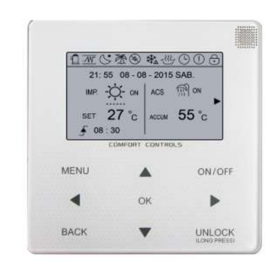
SISTEMA DI CONTROLLO Sblocco dello schermo Accensione / spegnimento Utilizzare l'interfaccia per attivare il modo CALDO o FRED- Se l'icona è visualizzata sullo schermo, il controllore è bloccato. Viene visualizzata la pagina: ■ é possibile tramite il tasto ON/OFF attivare l'unità solo se le impostazioni TERMOSTATO AMBIENTE (vedi sotto menu PER SERVIZIO ASSISTENZA TECNCA) sono impostate NO 21: 55 08 - 08 - 2015 SAB. -
Page 7: Modificare Il Setpoint Dell'acqua
SISTEMA DI CONTROLLO Modificare il setpoint dell'acqua 21: 55 08 - 08 - 2015 SAB. 21: 55 08 - 08 - 2015 SAB. 55 C ACCUM ON/OFF ON/OFF ON/OFF MODIFICA SCORRERE ON/OFF ■ Se il cursore è sul campo della temperatura usare i curso- ri ''◄'',''►'' per selezionare e usare i cursori ''▼'',''▲'' per 21: 55 08 - 08 - 2015 SAB. -
Page 8: Impostare Il Modo Di Funzionamento (Caldo / Freddo)
SISTEMA DI CONTROLLO ■ se le impostazioni TERMOSTATO AMBIENTE (vedi sotto Impostare il modo di funzionamento (CALDO / FREDDO) menu PER SERVIZIO ASSISTENZA TECNCA) sono impo- ■ E' possibile impostare il modo operativo tramite l'interfaccia state per gestire il cambio modo da ingresso digitale, se si premendo il tasto ''MENU'' e quindi selezionando >... -
Page 9: Modo Funzionamento
SISTEMA DI CONTROLLO Premere ''OK'', e ''■'' diventerà '' √ ''. La fascia oraria 1 sarà Modo funzionamento selezionata. Premere ''OK'' di nuovo, e ''√'' diventerà '' ■ ''. La fascia oraria 1 sarà deselezionata. Vedi anche il paragrafo Impostare il modo di funzioamen- to (CALDO / FREDDO). - Page 10 SISTEMA DI CONTROLLO Andare su ''MENU'' > ''TEMPERATURE PREDEFINITE''. Usare i tasti '◄'', ''►'' per scorrere. Premere ''OK'' per selezionare. Premere''OK''. ■ Se è stata attivata la funzione CURVE CLIMATICHE,non è possi- Apparirà la seguente pagina: bile modificare il setpoint dell'acqua tramite l'interfaccia, se si tenta TEMPERATURE PREDEFINITE di farlo premendo i tasti ''▼'', ''▲'' apparirà...
- Page 11 SISTEMA DI CONTROLLO Apparirà la seguente pagina: INFORMAZIONE TEMPERATURE PREDEFINITE Se STATO CORRENTE è OFF, il modo ECO non è attivo, Per attivarlo impostare a ON. TEMP. TIPOCUR MODO MODO PRE. VA CLIM. COMFORT Per attivare la programmazione oraria del modo ECO impo- stare ECO TIMER a ON.Impostare quindi INIZIO e FINE.
-
Page 12: Acqua Calda Sanitaria (Acs)
SISTEMA DI CONTROLLO Acqua calda sanitaria (ACS) INFORMAZIONE Usualmente il modo ECO è usato in combinazione col modo ANTILEGIONELLA COMFORT. La funzione ANTILEGIONELLA è usata per eliminare il mor- bo della legionella.Durante la funzione ANTILEGIONELLA la TEMPERATURE PREDEFINITE temperatura dell'acqua nel serbatoio ACS raggiungerà una temperatura di 65~70°C in base alle impostazioni dei para- TEMP. - Page 13 SISTEMA DI CONTROLLO FAST ACS RISCALDATORE SERBATOIO ACS La funzione FAST ACS è usata per forzare l'unità nel modo produzione acqua calda sanitaria. La funzione RISC ACC ACS è usata per forzare l'attivazione L'unità attiverà tutte le fonti di energia disponibili (compres- del solo riscaldatore elettrico del serbatoio ACS (se presente).
-
Page 14: Programmazione Oraria
SISTEMA DI CONTROLLO Programmazione oraria POMPA RICIRCOLO ACS Il menu PROGRAMMAZIONE ORARIA consente: La funzione POMPA DI RICIRCOLO ACS è usata per far cir- 1) TIMER per impostare la programmazione oraria giornaliera colare l'acqua calda nel circuito ACS. (in questo caso la stessa per tutti i giorni della settimana). Andare su ''MENU'' >... - Page 15 SISTEMA DI CONTROLLO Usare ''◄''or ''►'' per spostarsi e premere"OK". In questo Nella seguente tabella la sequenza oraria di funzionamento caso avendo selezionato i giorni da luned' avenrd' la pro- dell'unità: grammazione oraria sarà la stessa per tutti questi giorni della Time The operation of the controller settimana.
-
Page 16: Opzioni
SISTEMA DI CONTROLLO TIME (IMPOSTAZIONE DATA E ORA) Opzioni Il menu OPZIONI si compone dei seguenti sottomenu: Il menu TIME è usato per impostare la data e l'ora correnti. 1) MODO SILENZIAMENTO Andare su ''MENU''>''PROGRAMMAZIONE ORARIA'' > 2) VACANZA LONTANA ''TIME''. - Page 17 SISTEMA DI CONTROLLO Esempio: Vacanza invernale dal 02-02-2017 sino al 16-02-2016. Usare i tasti ''▼'',''▲'' per selezionare livellol 1 o livello 2. Pre- Impostare quindi: mere ''OK''. Attivare la funzione VACANZA LONTANO andando su Se si seleziona TIMER e si preme “OK” apparirà la pagina ''MENU'' >...
-
Page 18: Blocco Bambini
SISTEMA DI CONTROLLO SCORRERE VACANZE CASA Se il booster è attivato (cioè è impostato a SI' nel menu ser- vizio assistenza tecnica ''ALTRA SORGENTE DI RISCAL- Questa funzione può essere usata per sospendere la norma- DAMENTO''), apparirà la pagina seguente: le programmazione nel caso di una "vacanza"... -
Page 19: Informazioni Assistenza Tecnica
14:10 01-08-2015 14:00 01-08-2015 13:50 01-08-2015 13:20 01-08-2015 SISTEMA DI CONTROLLO SCORRERE CONFERMA premere ancora OK per evdere il significato del codice allarme: Informazioni assistenza tecnica Questo sottomenu consente di: 1) vedere il num. di telefono dell'assistenza tecnica 2) vedere la lista dei codici di allarme 3) vedere i principali parametri di funzionamento impostati 12:30 08-08-2015 SAB. -
Page 20: Parametri Di Funzionamento
SISTEMA DI CONTROLLO Parametri di funzionamento INFORMAZIONE In questo sottomenu è possibile vedere tutti i parametri di Se alcuni parametri non sono stati attivati (o disponibili) a funzionamento. display comparirà "--" ■ Andare su ''MENU'' > ''PARAMETRI DI FUNZIONAMENTO''. ■ Premere ''OK''. Ci sono 5 pagine di parametri, usare ''▼'',''▲'' per spostarsi. -
Page 21: Curve Climatiche In Modo Freddo
SISTEMA DI CONTROLLO Nelle tabelle sono indicati i valori di set point (T1S) al variare della temperatura aria esterna (T4) per le varie curve climatiche disponibili. Curve climatiche in modo freddo WTS COOLING MODE (low temp) MODO FREDDO (BASSA TEMPERATURA) MODO FREDDO (BASSA TEMPERATURA) 1_LT -5 ~ -14... -
Page 22: Panoramica Delle Pagine Disponiibli Utente
SISTEMA DI CONTROLLO Panoramica delle pagine disponiibli utente Lingua italiana... - Page 23 SISTEMA DI CONTROLLO Lingua inglese...
- Page 24 SISTEMA DI CONTROLLO Lingua italiana...
- Page 25 SISTEMA DI CONTROLLO Lingua inglese...
- Page 26 SISTEMA DI CONTROLLO Lingua italiana...
- Page 27 SISTEMA DI CONTROLLO Lingua inglese...
-
Page 28: Codici Di Errore E Azioni Correttive
CODICI DI ERRORE E AZIONI CORRETTIVE Quando un dispositivo di sicurezza è attivato, un codice di errore viene visualizzato sull'interfaccia utente. Un elenco di tutti gli errori e azioni correttive possono essere trovate nella tabella sottostante. Per eliminare il codice di errore spegnere l’unità premedo OFF e quindi riattivarla premendo ON. Nel caso in cui questa procedura non vada a buon fine, contattare il servizio assistenza tecnica. - Page 29 CODICI DI ERRORE E AZIONI CORRETTIVE Codi- Malfunzionamento Causa errore e azione correttiva o protezione 1. Verificare che le schede siano alimentate. Controllare se il LED su PCB B è acceso o spento. Errore di comunicazio- 2. Se è acceso controllare il cavo di connessione tra le due schede. ne tra scheda PCB A e 3.
- Page 30 CODICI DI ERRORE E AZIONI CORRETTIVE Malfunziona- Codi- mento Causa errore e azione correttiva o protezione Se l’unità sta funzionano in modo CALDO o ACS verificare: - Portata acqua bassa e quindi temperatura acqua troppo alta. Potrebbe essere dovuto a presenza aria nel circuito (eventualmnete sfiatare l’impianto) o a causa di perdite di carico troppo alte (aumentare la velocità...
- Page 31 SUMMARY THIS MANUAL IS DIVIDED INTO SECTIONS. THEIR NAMES APPEAR IN THE HEADING OF EACH PAGE. CONTROL SYSTEM ................4 The appearance of the wire control device.
-
Page 32: Control System
CONTROL SYSTEM The appearance of the wire control device Turn on or off the space operation mode or DHW mode turn on or off Enter the the function in the menu structure menu struc- ture from the page Navigate the cursor on the display/naviga- te in the menu... -
Page 33: Home Page
CONTROL SYSTEM Home page You can use the home pages to read out and change settings that are meant for daily usage. Depending on the system layout, the following home pages may be possible: ■ Room temperature (ROOM ) ■ Water flow temperature (MAIN) ■... -
Page 34: Screen Unlock
CONTROL SYSTEM Screen Unlock Turning ON/OFF controls Use the interface to turn on or off the unit for space If the icon is on the screen, the controller is locked. The heating or cooling. page is displayed: ■ The ON/OFF of the unit can be controlled by the interface if the ROOM TEHERMOSTAT is NON.(see ROOM THERMO- STAT SETTING on INSTALLATION &OWNER'S MANUAL) 21: 55 08 - 08 - 2015 SAT. -
Page 35: Adjusting The Temperature
21: 55 08 - 08 - 2015 SAT. MAIN CONTROL SYSTEM Adjusting the temperature 21: 55 08 - 08 - 2015 SAT. 21: 55 08 - 08 - 2015 SAT. MAIN ROOM 55 C TANK ON/OFF ADJUST SCROLL ON/OFF ON/OFF ON/OFF ■... -
Page 36: Adjusting Space Operation Mode (Heat/Cool)
CONTROL SYSTEM ■ If ROOM THERMOSTAT and MODE SETTING are set Adjusting space operation mode (HEAT/COOL) YES (for more details refer to paragraph " ROOM THERMO- STAT (ON/OFF - HEAT/COOL) by digital input".) the ope- ■ Adjusting space operation mode by interface ration mode of the unit is defined by the room thermostat, if Go to ''MENU'' >... -
Page 37: Operation Mode
CONTROL SYSTEM You press ''OK'', and the ''■'' becomes '' ''. The timer 1 is Operation Mode selected. You press ''OK'' again, and the '' '' becomes ''■''. The timer 1 See "Adjusting operation mode" . is unselected. Preset temperature PRESET TEMPERATURE PRESET TEMPERATUER has PRESET TEMP\WEATHER PRESET... - Page 38 CONTROL SYSTEM Use '◄'', ''►''to scroll .Press ''OK'' to select. Go to ''MENU'' > ''PRESET TEMPERATURE''>''WEATHER TEMP. SET''. Press''OK''. ■ If the weather TEMP.SET is actived,the desired tempera- The following page will appear: ture can not be adjusted on the interface.Press the ''▼'', ''▲'' to adjust the temperature on home page.
- Page 39 CONTROL SYSTEM The following page will appear: INFORMATION PRESET TEMPERATURE If CURRENT STATE is OFF, ECO MODE is not active. To activate it set ON. PRESET WEATHER COMFORT TEMP. TEMP.SET MODE MODE When the cursor scroll on start/end, as following page. CURRENT STATE PRESET TEMPERATURE ECO TIMER...
- Page 40 CONTROL SYSTEM Domestic Hot Water (DHW) INFORMATION Always the ECO mode is used combined with comfort mode. DISINFECT The DISINFECT function is used to kill the legionella. In disin- fect function the tank temperature will be reached 65~70°C. PRESET TEMPERATURE To set the parameters of this function refer to section "SETUP OF THE SYSTEM"...
- Page 41 CONTROL SYSTEM FAST DHW DHW TANK HEATER The FAST DHW function is used forced the system to opera- The tank heater function is used to force the tank heater to tion in DHW mode. heat the water in tank.In the same situation, the cooling or The heat pump and the booster heater or backup heater and heating is required and the heat pump system is operating for gas boiler will operate for DHW mode together.
-
Page 42: Domestic Hot Water (Dhw)
CONTROL SYSTEM DHW PUMP Schedule SCHEDULE menu contents as following: The DHW PUMP function is used to return water of the water 1) TIMER to set the day schedule (in this case the schedule net. Go to ''MENU'' > ''DOMESTIC HOT WATER'' > ''DHW is the same for all the days of the week). -
Page 43: Schedule
CONTROL SYSTEM Use ''◄''or ''►'' move to SET, press"ok".The Monday to Fri- The operation of the controller at the following time: day are selected to be scheduled and they have the same Time The operation of the controller schedule 1:00 DHW mode is turned ON The following pages will appear: 3:00... -
Page 44: Options
CONTROL SYSTEM Options TIME OPTIONS menu contents as following: The TIME function is used to set the local actual time and SILENT MODE date. HOLIDAY AWAY Go to ''MENU''>''SCHEDULE''>''TIME''. Press ''OK''. The fol- HOLIDAY HOME lowing page will appear: BACKUP HEATER SCHEDULE SILENT MODE TIMER... - Page 45 CONTROL SYSTEM Usage example: You go away during the winter. The current You can use ''▼'',''▲'' to select level 1 or level 2. Press ''OK''. date is 2016-01-31, two days later is 2016-02-02, it is the beginning date of the holiday. If the silent TIMER is selected, Press “OK”...
-
Page 46: Child Lock
CONTROL SYSTEM SCROLL ■ If the BACKUP HEATER is set YES in ''OTHER HEATING HOLIDAY HOME SOURCE'' (refer to SERVICEMAN menu), the following page will appear: The holiday home function is used to deviate from the normal schedules without having to change them during the holiday at home. -
Page 47: Service Information
14:10 01-08-2015 14:00 01-08-2015 13:50 01-08-2015 13:20 01-08-2015 CONTROL SYSTEM ENTER SCROLL Service information Press OK to show the mean of the error code: About service information Service information menu contents as following: 1) service call: to check service call for contacting; 12:30 08-08-2015 SAT. -
Page 48: Operation Parameter
CONTROL SYSTEM Operation Parameter INFORMATION This menu is for installer or service engineer to see all the if some parameter is not be activated (or available), the para- operation parameters. meter will show "--" . ■ At home page, go to ''MENU'' > ''OPERATION PARAMETER''. ■... -
Page 49: Weather Temperature Set For Cool Mode
CONTROL SYSTEM In the tables are riported the setpoint values (T1S) as function of the external air temperature (T4) for the different available weather temperature set. Weather temperature set for cool mode WTS COOLING MODE (low temp) COOL MODE (LOW TEMPERATURE) COOL MODE (LOW TEMPERATURE) 1_LT -5 ~ -14... -
Page 50: The Overview Pages Available User
CONTROL SYSTEM The overview pages available user Italian language... - Page 51 CONTROL SYSTEM English language...
- Page 52 CONTROL SYSTEM Italian language...
- Page 53 CONTROL SYSTEM English language...
- Page 54 CONTROL SYSTEM Italian language...
- Page 55 CONTROL SYSTEM English language...
-
Page 56: Error Code And Troubleshooting
ERROR CODE AND TROUBLESHOOTING When a safety device is activated, an error code will be displayed on the user interface. A list of all errors and corrective actions can be found in the table below. Reset the safety by turning the unit OFF and back ON. In case this procedure for resetting the safety is not successful, contact your local dealer. - Page 57 ERROR CODE AND TROUBLESHOOTING Error Malfunction or protection Failure cause and Corrective action code 1.wire doesn’t connect between indoor unit and outdoor unit. connect the wire. 2.Communication wire sequence is not right. Reconnect the wire in the right sequence. Communication error between 3.
- Page 58 ERROR CODE AND TROUBLESHOOTING Error Malfunction or protection Failure cause and Corrective action code Heating mode, DHW mode: 1. The water flow is low; water temp is high, whether there is air in the water system. Release the air. 2. Water pressure is lower than 0.1Mpa, charge the water to let the pressure in the range of 0.15~0.2Mpa.
- Page 59 La ditta costruttrice declina ogni responsabilità per le inesattezze contenute nel presente, se dovute ad errori di stampa o di trascrizioni. Si riserva il diritto di apportare modifiche e migliorie ai prodotti a catalogo in qualsiasi momento e senza preavviso.
- Page 60 Ferroli spa ¬ 37047 San Bonifacio (Verona) Italy ¬ Via Ritonda 78/A tel. +39.045.6139411 ¬ fax +39.045.6100933 ¬ www.ferroli.it...