Table of Contents
Advertisement
Quick Links
Advertisement
Table of Contents

Related Manuals for Ferroli RXA


Summary of Contents for Ferroli RXA
- Page 1 AIR-WATER CHILLERS AND HEAT PUMPS WITH AXIAL FANS TECHNICAL MANUAL...
-
Page 3: Table Of Contents
TABLE OF CONTENTS GENERAL FEATURES ................5 UNIT DESCRIPTION . -
Page 5: General Features
GENERAL FEATURES Unit description This series of air-water chillers and heat pumps has been designed to satisfy the air conditioning requirements of residential and commercial plants of small and medium size and can be applied both to fan coil plants and to radiant floor plants. All the units are suitable for outdoor installation. -
Page 6: Description Of Parts
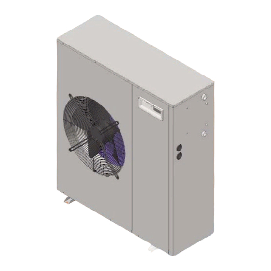
GENERAL FEATURES Description of parts The supporting structure (1), base and external panelling are made from hot galvanised steel sheet, painted with epoxy powers (colour RAL 7035) to ensure good resistance to atmospheric agents. The axial-type fans with curved profile blades (2)are housed in a sheet casing and are complete with safety grille. -
Page 7: Versions
GENERAL FEATURES The command and control electrical panel incorporated in the display and 4 buttons for displaying and possibly modifying all unit contains all the power, adjustment and safety components the unit’s operation parameters. A remote keyboard with all the necessary to guarantee correct operation. -
Page 8: Accessories
GENERAL FEATURES Accessories Coil protection grilles - GP It comprises a painted electrowelded grille that protects the finned coil. Rubber vibration dampers - AVG These reduce the transmission to the machine support surface of mechanical vibrations generated by the compressor and fans during their normal operation. -
Page 9: Technical Data And Performance
TECHNICAL DATA AND PERFORMANCE Technical data Frame Model 11.1 14.1 17.1 U.M. Electrical power supply V-ph-Hz 230-1-50 230-1-50 230-1-50 400-3N-50 230-1-50 400-3N-50 400-3N-50 400-3N-50 Compressor Type rotativo scroll Quantity n° Capacity steps 0 - 100 Oil charge 1,13 1,13 1,20 1,20 1,80 1,80... -
Page 10: Nominal Performance Ir
TECHNICAL DATA AND PERFORMANCE Nominal performance IR Frame Model 11.1 14.1 17.1 U.M. Electrical power supply 230-1-50 230-1-50 400-3N-50 230-1-50 400-3N-50 400-3N-50 V-ph-Hz Cooling (air 35 °C bs / water 12 - 7 °C ) Refrigerating capacity 6,20 7,40 9,40 9,40 10,8 10,8... -
Page 11: Performance In Cooling (Ir And Ip)
TECHNICAL DATA AND PERFORMANCE Performance in cooling (IR and IP) Refrigerating capacity 1,50 1,40 1,30 1,20 1,10 1,00 0,90 0,80 0,70 0,60 0,50 Tbs [°C] Power input 1,40 1,90 1,80 1,30 1,70 1,60 1,20 1,50 1,40 1,10 1,30 1,00 1,20 1,10 0,90 1,00... -
Page 12: Performance In Heating (Ip)
TECHNICAL DATA AND PERFORMANCE Performance in heating (IP) Heat output 1,30 1,20 1,10 1,00 0,90 0,80 0,70 0,60 0,50 Tbu [°C] Power input 1,50 1,40 1,40 1,30 1,30 1,20 1,20 1,10 1,10 1,00 1,00 0,90 0,90 0,80 0,80 0,70 0,70 0,60 0,50 0,60... -
Page 13: Weights Of Units
TECHNICAL DATA AND PERFORMANCE Weights of units Weight of unit [kg] Transport weight [kg] Frame Model 86.5 94.5 114.0 92.0 100.0 123.0 92.5 100.5 120.0 98.0 106.0 129.0 104.5 118.5 147.0 110.0 124.0 156.0 11.1 122.5 136.5 165.0 128.0 142.0 174.0 14.1 138.0... -
Page 14: Pressure Losses (Version Vb)
TECHNICAL DATA AND PERFORMANCE Pressure losses (version VB) 17.1 11.1 14.1 1000 1500 2000 2500 3000 3500 4000 Water delivery [l/h] Portata [l/h] Useful head (version VP and VA) 14.1 17.1 11.1 1000 1500 2000 2500 3000 3500 4000 Portata [l/h] Water delivery [l/h]... -
Page 15: Operation Limits
TECHNICAL DATA AND PERFORMANCE Operation limits The graphs provided below give the range within which correct operation of the unit is guaranteed. Use in different conditions from that indicated involves cancellation of the product warranty contract. Thermal head of water treated by the unit Minimum °C Maximum... -
Page 16: Dimensions
TECHNICAL DATA AND PERFORMANCE Dimensions Basic Version - VB Pump Version - VP Storage Version - VA Minimum operating space Respect the clearances around the unit indicated in the 1329 figure, to ensure adequate air circulation and to facilitate maintenance and control operations. Frame Model 6.1 - 7.1... -
Page 17: Connections
CONNECTIONS Plumbing connections For correct design of the plumbing system comply with the current local safety regulations. Always ensure an adequate flow of water through the unit’s plate-type exchanger, even if a differential pressure switch (connected between the exchanger inlet and outlet) that stops the unit in case of insufficient water flows, thus preventing the risk of freezing, is fitted standard. -
Page 18: Expansion Tank Setting
CONNECTIONS Expansion tank setting All the storage version units (VA) come complete with expansion tank and safety valve. The expansion tank prefilling pressure must be adequate for the total volume of the plumbing system to which the unit is connected. The factory setting (p = 2 bar g) corresponds to the minimum value necessary for avoiding negative pressure zones inside the water circuit and the risk of pump cavitation, in the event no users are located above the level on which the unit is installed. -
Page 19: Electrical Connections
CONNECTIONS Electrical connections The electrical wiring must be carried out by qualified personnel in conformity with the current regulations in the country of use at the time of installation. Before carrying out any work on the electrical system make sure the unit’s power supply line is disconnected at the start.