
Related Manuals for Interlogix TVP-6102


Summary of Contents for Interlogix TVP-6102
- Page 1 TruVision HD-TVI PTZ Camera (TVP-6101/ TVP-6102/ TVP-6103) Installation Guide P/N 1073485-EN • REV B • ISS 08OCT18...
- Page 2 Copyright © 2018 United Technologies Corporation, Interlogix is part of UTC Climate, Controls & Security, a unit of United Technologies Corporation. All rights reserved. Disclaimer Information in this document is subject to change without notice. No part of this document may be reproduced or...
- Page 3 European Union This product and - if applicable - the supplied accessories directives too are marked with "CE" and comply therefore with the applicable harmonized European standards listed under the EMC Directive 2014/30/EU, the RoHS Directive 2011/65/EU. 2012/19/EU (WEEE directive): Products marked with this symbol cannot be disposed of as unsorted municipal waste in the European Union.
- Page 4 Contact information For contact information and to download the latest and manuals/ tools/ manuals, tools, and firmware, go to the web site of your firmware region. Americas: www.interlogix.com EMEA: www.firesecurityproducts.com Manuals are available in several languages. Australia/New Zealand: www.utcfs.com.au...
-
Page 5: Table Of Contents
Content Introduction 3 Product overview 3 HD-TVI 1080P PTZ Cameras 3 HD-TVI 1080P IR PTZ Cameras 3 Contact information and manuals/tools/firmware 3 Installation 4 Installation environment 4 Package contents 5 Pendant/Wall HD-TVI PTZ 5 Surface/Flush HD-TVI PTZ 7 Pendant/Wall IR HD-TVI PTZ 10 Cable requirements 11 DIP switch settings including selecting HD-TVI or Analog output 12... - Page 6 Using the camera with a TruVision recorder or another system 50 Programming 50 Change the video format (NTSC/PAL) 51 Menu tree 51 Specifications 53 TruVision Pendant/Wall HD-TVI PTZ Camera (TVP-6101) 53 TruVision Surface/Flush HD-TVI PTZ (TVP-6102) 53 TruVision Pendant/Wall IR HD-TVI PTZ (TVP-6103) 54 Installation Guide...
-
Page 7: Introduction
Introduction Product overview This is the installation guide for TruVision HD-TVI PTZ Camera (TVP-6101/ TVP-6102/ TVP-6103) models: HD-TVI 1080P PTZ Cameras TVP-6101 (32X, Pendant/Wall mount) TVP-6102 (32X, Surface/Flush mount) HD-TVI 1080P IR PTZ Cameras TVP-6103 (32X, Pendant/Wall mount, IR) ... -
Page 8: Installation
Installation This section provides information on how to install the cameras. Installation environment When installing your product, consider these factors: • Electrical: Install electrical wiring carefully. It should be done by qualified service personnel. Always use a CE certified power supply (24VAC) to power the camera. Do not overload the power cord or adapter. -
Page 9: Package Contents
be used for an extended period of time, put on the lens cap to protect the sensors from dirt. Package contents Check the package and contents for visible damage. If any components are damaged or missing, do not attempt to use the unit;... - Page 10 Desiccant 1 Desiccant 2 • • (Two small bags. (One large bag. Used Used as the spare to keep the two bags desiccant for the PTZ. of desiccant away To use this desiccant, from moisture prior to place it inside the cup use).
-
Page 11: Surface/Flush Hd-Tvi Ptz
Equipment Disposal • and Battery Disposal documents Surface/Flush HD-TVI PTZ Camera Housing ring • • Trim ring Drill template • • (224 mm/8.82 in.) Installation Guide... - Page 12 Desiccant 1 Desiccant 2 • • (Two small bags. Used as (One large bag. the spare desiccant for the Used to keep the PTZ. To use this two bags of desiccant, place it inside desiccant away the cup base and tie it with from moisture prior the zip tie below.) to use.)
- Page 13 Fixation pin (4 pcs) Installation guide • • Equipment Disposal and • Battery Disposal documents Installation Guide...
-
Page 14: Pendant/Wall Ir Hd-Tvi Ptz
Pendant/Wall IR HD-TVI PTZ Camera Safety lanyard • • Wrench (M4) • Desiccant 1 Desiccant 2 • • (Two small bags. Used (One large bag. Used as the spare desiccant to keep the two bags of for the PTZ. To use this desiccant away from desiccant, place it inside moisture prior to use). -
Page 15: Cable Requirements
Equipment Disposal and • Battery Disposal documents CAUTION: Use direct plug-in UL listed power supplies marked Class 2/CE certified or LPS (limited power source) of the required output rating as listed on the unit. CAUTION: Risk of explosion if the battery is replaced by an incorrect type. -
Page 16: Dip Switch Settings Including Selecting Hd-Tvi Or Analog Output
DIP switch settings including selecting HD-TVI or Analog output HD-TVI PTZ For pendant/wall PTZ cameras, access the DIP switch by removing the rubber plugs on the two sides of the PTZ housing and unscrewing the two screws inside. Then open the bubble assembly, remove all three foam inserts and the plastic protective lens cover (see Figure 1). - Page 17 Figure 2: DIP switch location for surface/flush mount PTZ DIP switch Figure 3: Enlarged view of the DIP switch Address settings Use the SW1 switches from 1 to 4 to set the PTZ address. Refer to Table 1 on setting the PTZ address to a specific number.
- Page 18 Switch no. Dome address Protocol settings Use SW1 switches 5, 6 and 7 to set the PTZ protocol. Refer to Table 2 below: Installation Guide...
- Page 19 Table 2: Set the dome protocol SW1 switch no. Protocol Interlogix RS-485 PROTOCOL_PELCO_P PROTOCOL_PELCO_D PROTOCOL_DIGIPLEX PROTOCOL_RS422_ASCII PROTOCOL_BOSCH_CODE PROTOCOL_AD_CODE Output signal settings Use SW1 switch number 8 to set the output signal of the PTZ. Refer to the Table 3 below: Table 3: Set the HD-TVI mode SW1 switch no.
-
Page 20: Ir Pendant/Wall Mount Hd-Tvi Ptz
19200 bps. The baud rate will be set as 2400 bps by default if it is out of this range. Refer to Table 4 below: Table 4: Set the baud rate of the dome SW2 switch no. Baud rate 2400 4800 9600 19200... - Page 21 Figure 4: Label of DIP switch for pendant/wall mount HD- TVI IR Figure 5: Enlarged view of the DIP switches Note: The default dome address is 0. The default baud rate is 2400. The default value of the 120Ω terminator is OFF. Address settings ...
- Page 22 Switch no. Dome address OFF OFF OFF OFF OFF OFF OFF OFF OFF OFF OFF OFF OFF OFF OFF OFF OFF OFF OFF OFF OFF OFF OFF OFF OFF OFF OFF OFF OFF OFF OFF OFF OFF OFF OFF OFF OFF OFF OFF OFF OFF OFF OFF OFF OFF OFF OFF OFF...
- Page 23 Switch no. Dome address ON OFF OFF OFF ON OFF OFF OFF ON OFF OFF OFF ON OFF OFF OFF ON OFF OFF OFF ON OFF OFF OFF ON OFF OFF OFF ON OFF OFF OFF OFF ON OFF OFF OFF ON OFF OFF OFF ON OFF OFF OFF ON OFF OFF...
- Page 24 Switch no. Dome address OFF ON OFF OFF OFF ON OFF OFF OFF ON OFF OFF ON OFF OFF ON OFF OFF ON OFF OFF ON OFF OFF ON OFF OFF ON OFF OFF ON OFF OFF ON OFF OFF ON OFF OFF ON OFF OFF ON OFF OFF...
- Page 25 Switch no. Dome address OFF OFF ON OFF OFF ON OFF OFF ON OFF OFF ON OFF OFF ON OFF OFF ON OFF OFF ON OFF OFF ON OFF OFF ON OFF OFF ON OFF OFF ON OFF OFF ON OFF OFF ON OFF OFF ON ON OFF ON...
- Page 26 Switch no. Dome address ON OFF ON ON OFF ON ON OFF ON ON OFF ON ON OFF ON ON OFF ON ON OFF ON ON OFF ON ON OFF ON OFF ON OFF ON OFF ON OFF ON OFF ON OFF ON OFF ON OFF ON...
- Page 27 Switch no. Dome address OFF ON OFF ON OFF ON OFF ON OFF OFF OFF Installation Guide...
- Page 28 Switch no. Dome address OFF OFF OFF OFF OFF OFF OFF OFF OFF OFF OFF OFF OFF OFF OFF OFF OFF OFF OFF OFF OFF OFF OFF OFF OFF OFF OFF OFF OFF OFF OFF OFF OFF OFF OFF OFF OFF OFF OFF OFF OFF OFF OFF OFF OFF...
- Page 29 Switch no. Dome address ON OFF OFF ON OFF OFF ON OFF OFF ON OFF OFF ON OFF OFF ON OFF OFF ON OFF OFF ON OFF OFF ON OFF OFF ON OFF OFF OFF ON OFF OFF ON OFF OFF ON OFF OFF ON OFF OFF ON OFF...
- Page 30 Switch no. Dome address OFF ON OFF OFF ON OFF OFF ON OFF OFF ON OFF OFF ON OFF ON OFF ON OFF ON OFF ON OFF ON OFF ON OFF ON OFF ON OFF ON OFF ON OFF ON OFF ON OFF ON OFF ON OFF...
- Page 31 Switch no. Dome address OFF OFF ON OFF OFF ON OFF OFF ON OFF OFF ON OFF OFF ON OFF OFF ON OFF OFF ON OFF OFF ON OFF OFF ON OFF OFF ON OFF OFF ON OFF OFF ON OFF OFF ON OFF OFF ON OFF OFF ON...
- Page 32 Switch no. Dome address ON OFF ON ON OFF ON ON OFF ON ON OFF ON ON OFF ON ON OFF ON ON OFF ON ON OFF ON ON OFF ON ON OFF ON ON OFF ON OFF ON OFF ON OFF ON OFF ON OFF ON...
- Page 33 Switch no. Dome address OFF ON OFF ON OFF ON OFF ON OFF ON OFF ON Installation Guide...
- Page 34 Switch no. Dome address Baud rate settings Use the SW2 switch numbers 1 and 2 to set the baud rate of the PTZ. The baud rate can be 2400 bps, 4800 bps, 9600 bps or 19200 bps. The baud rate will be set as 2400 bps by default if it is out of this range.
- Page 35 Protocol settings Use SW2 switches numbers 3, 4 and 5 to set the PTZ protocol. Refer to Table 2 below: Table 7: Set the dome protocol SW2 switch no. Protocol Interlogix RS-485 PROTOCOL_PELCO_P PROTOCOL_PELCO_D PROTOCOL_DIGIPLEX PROTOCOL_RS422_ASCII PROTOCOL_BOSCH_CODE PROTOCOL_AD_CODE Output signal settings ...
-
Page 36: Termination Resistor Settings
Termination resistor settings Use SW2 switch number 8 to turn on/off the 120Ω termination resistor. When multiple PTZs are controlled through one RS- 485 bus in serial mode, there must be a termination resistor at the end of the RS-485 bus according to the RS-485 protocol standard. - Page 37 Locate the two pins near the corner of the dome drive base. Installation Guide...
- Page 38 Turn on the termination resistor by inserting a jumper wire to connect the two pins. Installation Guide...
-
Page 39: Camera Description
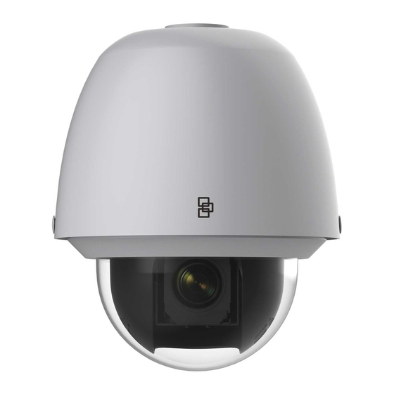
Camera description Figure 6: Outdoor HD-TVI PTZ ① ② ③ ALARM_OUT1 ALARM_COM1 ④ ALARM_IN1 ALARM_IN2 ALARM_GND ⑤ ⑥ HD-TVI output (White), HD- 2 alarm inputs TVI or 960H Analog (YELLOW/BLUE- selectable via DIP switch. ALARM_IN1, See the output signal YELLOW/ORANGE- settings section on page 15. - Page 40 Figure 7: Indoor HD-TVI PTZ ① ② ③ ALARM_OUT1 ALARM_COM1 ④ ALARM_IN1 ALARM_IN2 ALARM_GND ⑤ ⑥ HD-TVI output (White) 2 Alarm inputs selectable via DIP (YELLOW/BLUE- switch. See the output ALARM_IN1, signal settings section YELLOW/ORANGE- on page 15. ALARM_IN2) / 1 alarm output (WHITE/RED- Power supply ALARM_OUT1)
- Page 41 Figure 8: IR outdoor HD-TVI PTZ ① ② ③ ④ HD-TVI output (White) RS-485 port selectable via DIP switch. a. Orange RS-485+ See the output signal b. Yellow RS-485- settings section on page Housing Power supply a. Black 24 VAC b.
-
Page 42: Ir Illuminators
IR illuminators The IR PTZ camera’s built-in IR illumination provides high- quality video in low-light environments, even when there is no other illumination available. You can configure the IR illumination using the OSD menu or a recorder such as TVN and TVR. If the function is enabled, the IR light is ON when the camera enters night (black and white) mode. - Page 43 To mount the wall mount: Remove the rubber plugs on the two sides of the PTZ housing. Unscrew the two screws located below the rubber plugs. Open the bubble assembly and remove the foam insert and the plastic protective lens cover. Set the address and baud rate for the dome as shown on the page 17.
-
Page 44: Mount The Camera On The Wall Mount
Mount the camera on the wall mount To mount the outdoor HD-TVI PTZ: Hang the safety lanyard towards the dome and then hook the dome to the wall mount, as shown below. Route the cables from the wall mount. Install the PTZ to the mount, and secure the PTZ using the screws enclosed with the mount. - Page 45 To mount the pendant/wall IR HD-TVI PTZ: Set the address and baud rate for the dome shown on the page 17. Hang the safety lanyard towards the HD-TVI PTZ and then hook the dome to the wall mount, as shown below. Route the cables of the PTZ through the wall mount.
-
Page 46: Flush Mount The Camera
Flush mount the camera Flush-mounting is suitable for indoor ceiling construction. The following requirements are mandatory preconditions for mounting: The height of the space above the ceiling must be greater than 250 mm (9.843 in). The thickness of the ceiling must be between 5 and ... - Page 47 Back box Protective foam Sticker Lower dome Remove the protective lens cover, foam and sticker from the dome drive. Set the address and baud rate for the HD-TVI dome. See page 12. Attach the lower dome to the back box. Rotate it clockwise to secure it.
- Page 48 Adjust the height of the two housing tabs by turning the screw on which they are attached. The distance of the tabs from the housing ring must be greater than the thickness of the ceiling. Housing tab Screw Make sure that the housing tab is closed and then PUSH the housing into the pass-through hole.
-
Page 49: Surface Mount The Camera
Arrow label Notch Note: Remove the protective film on the lower dome when the installation is completed. In order to obtain clear video images, wear anti-static gloves when you install the PTZ. Surface mount the camera Use surface mounting for indoor/outdoor solid ceiling construction. - Page 50 To mount the surface/flush HD-TVI PTZ to a ceiling: Note: When installing the PTZ to a ceiling, do not use drywall anchors. Remove the mounting bracket. Remove the four screws on the back box using a screwdriver. Remove the in-ceiling mount. Screw the four fixation pins onto the back box using a screwdriver.
- Page 51 Wire the dome. Route the cables of the dome either from the top or the side of the back box. For the cables routed from the top of the back box, you must drill a cable hole in the ceiling. Surface mounting: Rotate the lower dome counterclockwise to separate it from the back box.
- Page 52 If you route cables from the top of the back box, mark the cable hole on the ceiling and drill a hole. Secure the mounting base to the ceiling with Phillips screws. If the PTZ is installed onto a wooden wall, use the ...
- Page 53 Screw holes Cable hole Install the HD-TVI PTZ on to the mounting base. Route the cables for the HD-TVI dome. Align the base of the HD-TVI dome with the mounting base. Align the direction of the arrow with the spring end of the mounting base.
-
Page 54: Using The Camera With A Truvision Recorder Or Another System
② Push Forwards Spring Line up Lock Clip ① Push Upwards Note: Please remove the protective film on the lower dome after the installation is finished. Do not touch the bubble of the lower dome directly with your hand. The image will be blurred. Using the camera with a TruVision recorder or another system Please refer to the recorder user manual for instructions on... -
Page 55: Change The Video Format (Ntsc/Pal)
view of the DVR, select Menu from the PTZ control panel or call Preset 95. The camera setup menu appears (see the menu tree below). To select an OSD item, click the directional buttons up/down. To adjust the value of a selected item, click the directional buttons left/right. - Page 56 Installation Guide...
-
Page 57: Specifications
-30 to +65 °C (-22 to +149°F) Dimensions 220 × 226 mm (8.66 × 10.5 in.) Weight 3 kg (6.61 Ib.) Environmental rating IP66, IK10 TruVision Surface/Flush HD-TVI PTZ (TVP-6102) Electrical Voltage input 24 VAC Power consumption Max. 18 W Miscellaneous Connectors... -
Page 58: Truvision Pendant/Wall Ir Hd-Tvi Ptz (Tvp-6103)
Dimensions Flush: 246 × 245 mm (9.69 × 9.65 in.) Surface: 179.8 × 239 mm (7.07 × 9.41 in.) Weight 3 kg (6.61 Ib.) Environmental rating IP54, IK10 TruVision Pendant/Wall IR HD-TVI PTZ (TVP-6103) Electrical Voltage input 24 VAC Power consumption Max.