
Related Manuals for Interlogix TVW-6101


Summary of Contents for Interlogix TVW-6101
- Page 1 TruVision HD-TVI (1080P) / Analog Wedge Camera Installation Guide TVW-6101 P/N 1073422-EN • REV A • ISS 14MAY18...
-
Page 3: Table Of Contents
Content Product overview 2 Contact information and manuals/tools/firmware 2 Package contents 3 Camera description 6 Installation 7 Program 14 Using a TVI output 15 Call up the camera OSD (On Screen Display) menu 15 Menu tree 18 Video format (NTSC/PAL) 19 Specifications 19 Legal and Regulatory information 20 Installation Guide... -
Page 4: Product Overview
Product overview This is the Installation Guide for the HD-TVI (1080P) / analog wedge camera TVW-6101. This guide describes a standard installation. The configuration manual is available from our web site. Contact information and manuals/tools/firmware For contact information and to download the latest manuals, tools, and firmware, go to the web site of your region. -
Page 5: Package Contents
Package contents Camera 3 M4 x 25 mm assembly (cable screws and 3 harness not anchors for wall shown) or ceiling installation Camera drill 2 screws M4 x 8 template used for installing the camera to the adapter plate Installation Guide... - Page 6 Torx wrench Adapter plate Adapter plate drill 12 VDC template connector (2 terminal connectors with positive and negative indicators) Lens adjustment Installation guide tool Installation Guide...
- Page 7 Equipment • disposal sheet Installation Guide...
-
Page 8: Camera Description
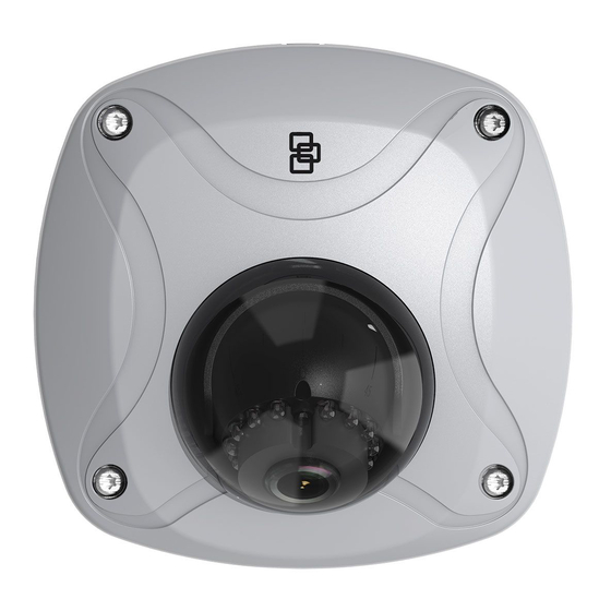
Camera description 12 VDC power cable TVI / 960H analog switch TVI / 960H analog video output Power LED OSD menu button MIC (Audio not supported) Camera housing Installation Guide... -
Page 9: Installation
Note: When using the HD-TVI output, the HD-TVI wedge camera should only be connected to a DVR that supports a TVI signal. Installation To install the camera on a surface: Use the camera drill template to mark the mounting holes. Follow all local safety regulations. - Page 10 Install the mounting base to the surface using two of the M4 x 25 mm screws and anchors. If routing the cable harness through the ceiling, do so prior to mounting the camera. Loosen the Philips screw, located near the lens assembly.
- Page 11 in the correct location. The tool is also used to adjust the tilt angle. Philips screw Lens adjustment tool Tilt Rotation Installation Guide...
- Page 12 Note: Please do not remove the foam ring attached to the lens. This foam ring is required to reduce the glare of IR illuminators. Tighten the Torx screw and re-install the housing cover to the camera assembly using the Torx wrench. To install the camera using the adapter plate: Use the adapter plate drill template to mark the holes.
- Page 13 Follow all local safety regulations. Drill through the mounting surface. If you need to route the cables from the bottom of the camera, drill a larger hole for the cable harness. Install the adapter plate to the using two of the M4 x 25 mm screws and anchors.
- Page 14 Using the Torx wrench, loosen the four screws to remove the housing cover from the device. Install the camera base to the adapter plate using the two M4 x 8mm screws. Loosen the Philips screw located near the lens assembly. Align the lens adjustment tool with the two small holes located on the camera assembly.
- Page 15 Rotate (pan) the camera assembly using the lens adjustment tool until the lens is positioned in the correct location. The tool is also used to adjust the tilt angle. Philips screw Lens adjustment tool Tilt Rotation Installation Guide...
-
Page 16: Program
Note: Please do not remove the foam ring attached to the lens. This foam ring is required to reduce the glare of IR illuminators. Tighten the Philips screw and re-install the housing cover to the camera assembly using the Torx wrench. Program In HD-TVI or Analog mode, use the OSD (On Screen Display) button to program the camera. -
Page 17: Using A Tvi Output
Using a TVI output Once the camera has been installed, you can configure the camera settings on the TVI DVR. Connect the TVI cable to the DVR, as shown. TruVision Coax Select the PTZ protocol and click Menu button to call up the camera menu. For more details, refer to the TVI DVR user manual. - Page 18 In live view of the desired camera, click the PTZ Control icon on the live view toolbar to access the PTZ control panel. To call up the camera setup menu: From the camera OSD of the DVR, select Menu. — or — From the DVR, select Iris+.
- Page 19 Iris+ Click to enter the submenu or to confirm the selected item. Exit When the setup is complete, select Iris+ click to exit the camera OSD. Note: You cannot exit the camera setup menu using the Menu button on the camera. Installation Guide...
-
Page 20: Menu Tree
Menu tree Installation Guide... -
Page 21: Video Format (Ntsc/Pal)
Video format (NTSC/PAL) Under Format, select PAL or NTSC. Specifications Power supply 12 VDC Current 290 mA max. 3.5 W max. Power consumption -40 to +60 °C (-40 to +140 °F) Operating temperature range Weight (net) 260 g (0.57 lb.) Dimensions 99.5 x 97 x 46.8 mm (3.92 x 3.82 x 1.84 in. -
Page 22: Legal And Regulatory Information
Legal and Regulatory information Copyright: © 2018 United Technologies Corporation, Interlogix is part of UTC Climate, Controls & Security, a unit of United Technologies Corporation. All rights reserved. Trademarks and patents: Trade names used in this document may be trademarks or registered trademarks of the manufacturers or vendors of the respective products. - Page 23 harmful interference to radio communications. Operation of this equipment in a residential area is likely to cause harmful interference in which case the user will be required to correct the interference at his own expense. ACMA compliance Notice! This is a Class A product. In a domestic environment this product may cause radio interference in which case the user may be required to take adequate measures.
- Page 24 Contact information and manuals / tools / firmware: For contact information and to download the latest manuals, tools, and firmware, go to the web site of your region. Americas: www.interlogix.com EMEA: www.firesecurityproducts.com Manuals are available in several languages Australia/New Zealand: www.utcfs.com.au...