Table of Contents
Advertisement
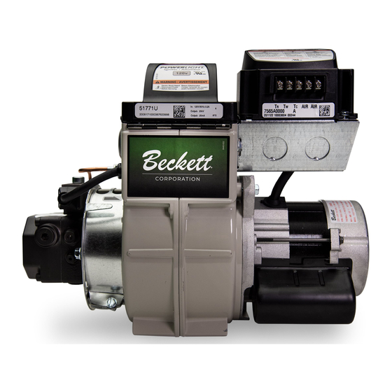
Beckett
Beckett
WARNING
!
Potential for Fire, Smoke and Asphyxiation Hazards
Incorrect installation, adjustment, or misuse of this burner could result in death, severe
personal injury, or substantial property damage.
To the Homeowner or Equipment Owner:
Please read and carefully follow all instructions
provided in this manual regarding your responsi-
bilities in caring for your heating equipment.
Contact a professional, qualifi ed service agency
for installation, start-up or service work.
Save this manual for future reference.
RWB 6104 BAFG R02
AF/AFG
Oil Burner Manual
Type 'M' Air Tube Combination
(AFG Models only)
Type 'L1' Head
To the Professional, Qualifi ed Installer or
Service Agency:
Please read and carefully follow all instructions
provided in this manual before installing, starting,
or servicing this burner or heating system.
The Installation must be made in accordance with
all state and local codes having jurisdiction.
Type 'V1' Head
Page 1
Advertisement
Table of Contents

Related Manuals for Beckett AF


Summary of Contents for Beckett AF
- Page 1 AF/AFG WARNING Potential for Fire, Smoke and Asphyxiation Hazards Incorrect installation, adjustment, or misuse of this burner could result in death, severe personal injury, or substantial property damage. To the Homeowner or Equipment Owner: Please read and carefully follow all instructions provided in this manual regarding your responsi- bilities in caring for your heating equipment.
-
Page 2: Table Of Contents
Parts Diagram Beckett Limited Warranty Information This manual contains information that applies to both AF and AFG burners. These burners may appear to be basically identical, but there are differences in design and performance. Please review the comparison chart below:... -
Page 3: General Information
Do NOT remove the air guide from the AFG chassis. Do NOT use ‘M’ Series air tube combinations on AF Burn- ers. Never try to convert and AF to and AFG or vice versa Any design alteration will: Void UL Listing Void manufacturer’s warranties... -
Page 4: Table 1 Burner Specifi Cation
General Specifi cations Table 1 – Burner Specifi cations Capacity ‘F’ Head (AF & AFG) (Note 1) Firing rate range: ...0.40 – 3.00 GPH Input: ... 56,000 – 420,000 Btu ‘L1’ Head (AFG Only) Firing rate range: ...0.40 - 1.10 GPH Input: ... -
Page 5: Notice Special Requirements
Concealed damage — If you discover damage to the burner or controls during unpacking, notify the carrier at once and fi le the appropriate claim. When contacting Beckett for service information — Please record the burner serial number (and have available when calling or writing). You will fi... -
Page 6: Clearances To Burner And Appliance
Outside air kit applications Refer to separate instruction sheet supplied with AF/AFG outside air kit for installation. This optional kit allows combustion air to be piped directly to the burner (Beckett part number 51747). Clearances to burner and appliance Provide space around burner and appliance for easy service and maintenance. -
Page 7: Attach Air Tube
Attach air tube (if not already installed) If using a fl ange and gasket, slide them onto the air tube. Then attach the air tube to the burner chassis using the four sheet metal screws provided. Refer to Figure 3 for details. -
Page 8: Check/Adjust 'Z' Dimension - F Heads
You will need to reset the “Z” dimension if you replace the air tube or nozzle line assembly. The Beckett Z gauge (part number Z-2000) is available to permit checking the F head “Z” dimension without removing the burner from the appli- ance. - Page 9 Place the end of a ruler at the leading edge of the head and, us- ing a straight edge across the end of the air tube, measure the distance to the end of the tube. A Beckett T501 gauge may also be used.
-
Page 10: Servicing Nozzle Line Assembly
Bolt the burner to the appliance using the fac- tory-mounted fl ange or an adjustable fl ange. Mounting dimensions When using the Beckett universal adjustable fl ange, mount the air tube at a 2° downward pitch unless otherwise specifi ed by the appli- ance manufacturer. -
Page 11: Wire Burner
Fuel supply below the level of the burner – When the fuel supply is more than eight feet below the level of the burner, a two-pipe fuel supply sys- tem is required. Depending on the fuel line diam- eter and horizontal and vertical length, the instal- lation may also require a two-stage pump. - Page 12 6. RUN. The burner runs until the call for heat is sati- fi ed. The burner is then sent to burner motor off delay, if applicable, or it is shut down and sent to standby.
-
Page 13: Start-Up Burner/Set Combustion
fi re and asphyxiation hazards. Do not attempt to start the burner when excess oil has accumulated in the appliance, the appliance is full of vapor, or when the combustion chamber is very hot. -
Page 14: Perform Regular Maintenance
Referring to the fi gure below, slide the new blower wheel onto the shaft. Use a feeler gauge to set the wheel-to-motor gap, as shown below. (AF = 0.125 +1/64 inch, AFG = 0.030 +1/64 inch) Slide blower wheel toward motor until it con- tacts feeler gauge. -
Page 15: Parts Diagram
5782 5940 3666 5685 51814U ** Contact your Beckett Representative for part num- ber and pricing. Parts that are unique to AF burn- ers replace parts numbered 6 and 31841 AIR INLET BELL 14. Refer to parts list below for part 2459U BLOWER WHEEL numbers. - Page 16 Beckett Burners, Beckett-branded major components and non-Beckett-branded major components that came as original equipment on a Beckett burner or were sold as a replacement part by Beckett should be returned, freight prepaid, to Beckett’s home office. Credit will be issued to the customer unless the returned equipment is determined by Beckett to be out of warranty or damaged by user, in which case the equipment will be scrapped.