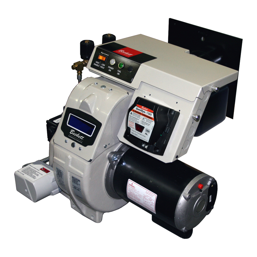
Beckett CF1400 Manual
Beckett oil burner manual cf1400, cf2300
Hide thumbs
Also See for CF1400:
- Setup manual (36 pages) ,
- Instruction manual (16 pages) ,
- User manual (24 pages)
Table of Contents
Advertisement
Quick Links
WARNING
!
Potential for Fire, Smoke and Asphyxiation Hazards
Incorrect installation, adjustment, or misuse of this burner could result in death, severe
personal injury, or substantial property damage.
To the Homeowner or Equipment Owner:
Please read and carefully follow all instructions pro-
vided in this manual regarding your responsibilities in
caring for your heating equipment.
Contact a professional, qualifi ed service agency for in-
stallation, start-up or service work.
Save this manual for future reference.
Form 6104 BCF23-R05
To the Professional, Qualifi ed Installer or
Service Agency:
Please read and carefully follow all instructions pro-
vided in this manual before installing, starting, or ser-
vicing this burner or heating system.
The Installation must be made in accordance with all
state and local codes having jurisdiction.
1
Advertisement
Table of Contents

Related Manuals for Beckett CF1400


Summary of Contents for Beckett CF1400
- Page 1 WARNING Potential for Fire, Smoke and Asphyxiation Hazards Incorrect installation, adjustment, or misuse of this burner could result in death, severe personal injury, or substantial property damage. To the Homeowner or Equipment Owner: Please read and carefully follow all instructions pro- vided in this manual regarding your responsibilities in caring for your heating equipment.
-
Page 2: Table Of Contents
Set appliance limit controls ... 19 Prepare the fuel unit for air venting ... 19 Start the burner ... 19-20 Start burner and vent air from oil line ... 20 Set high-fi re air ... 20 Set low-fi re air ... 20 Sequence of operation ... -
Page 3: General Information
Form 6104 BCF23-R05 To the Owner: Thank you for purchasing a Beckett burner for use situation, with your heating appliance. Please pay attention to the Safety Warnings contained within this instruction manual. -
Page 4: Owner's Responsibility
fi re hazards. The burner cannot properly burn the fuel if it is not sup- plied with a reliable combustion air source. Follow the guidelines in the latest editions of the NFPA 31 and CSA-B139 regarding providing adequate air for combustion and ventilation. -
Page 5: Fuel Supply
The fuel supply piping and tank must provide #1 or #2 fuel oil at pressure or vacuum conditions suitable for the fuel unit (oil pump) on the burner. Refer to fuel unit literature in the literature envelope in the burner carton to verify allowable suction pressure. -
Page 6: Vent System
The fl ue gas venting system must be in good condition and must comply with all applicable codes. Verify burner components — Burner box, Model CF1400 or CF2300A Air tube assembly Mounting fl ange kit Pedestal mounting assembly kit (recommended) Oil nozzle, per Table 1 —... -
Page 7: Verify Air Tube
Verify air tube The information in this section may be disregarded if the air tube is supplied by the appliance manufacturer. On the CF1400, there are two tube arrangements available – Tube A — 4.0 to 11.0 GPH per Table 2 Tube B —... -
Page 8: Stray Light
The control must detect a dark, no-fl ame condition in order to start the burner or it will hold in the stray light lockout mode. Shield the burner view window from direct expo- sure to intense light. -
Page 9: Mount Air Tube To Burner
Remove the rear access door from the back of the burner for improved access to the interior. Attach the air tube to the burner with the bolts and acorn nuts provided. The acorn nuts must go on the outside of the burner, with the bolts inserted from the inside. -
Page 10: Install Nozzle Line Assembly
Loosen acorn nut (item d) in Figure 5. Slide the nozzle line and plate assembly until dimension Z in Figure 5 is 1-3/4 ±1/16” (CF1400 and CF2300). When dimension Z (from end of air tube to fl at area of front face of head) is correctly set, tighten acorn nut (item d). -
Page 11: Insert Burner
See Figure 8. Install the pedestal support kit (recommended) by attaching the 3/4” npt fl ange (item a) to the bottom of the burner using the (4) #10 screws provided. Cut and thread (one end only) a 3/4” pipe nipple (item b) with length 11 inches less than dimension D in Figure 8. -
Page 12: Connect Fuel Lines
fi re and injury hazards. Models CF1400 and CF2300 are shipped with the pump bypass plug installed. Do not remove the bypass plug from the pump. It is required for step-fi... - Page 13 Figure 10 – Two-pipe oil fl ow with “B” pump 300 psig high fire 125 to 175 psig low fire Table 3 – Fuel unit gearset capacities Model Fuel Unit Model Number CF1400 B2TA-8245 CF2300 B2TA-8852 Form 6104 BCF23-R05 Field-installed by-pass loop...
-
Page 14: Wire The Burner
Perform all wiring in compliance with the National Electric Code ANSI/NFPA 70 (Canada CSA C22.1). Install the burner and all wiring in accordance with the National Electrical Code and all applicable local codes or requirements. Wire the burner in compliance with all instructions provided by the appliance manufacturer. -
Page 15: Sequence Of Operation
7. Recycle — If the fl ame is lost while the burner is fi ring, the control shuts down the burner, enters a 60-second recycle delay, and then repeats the ignition steps outlined above. -
Page 16: Prepare The Burner For Start-Up
If any of these items are not clear or are unavailable, call Beckett at 1-800-645-2876 for assistance. Start-up checklist – Verify the following before at- tempting to start burner. Combustion air supply and venting have been inspected and verifi... - Page 17 Figure 12 – Adjusting plate initial setting, typical Table 4a. CF1400 Initial indicator adjustment plate settings Head Position Tube Approximate Firing Rate Head Setting (gph) 4.00 4.50 5.00 6.00 7.00 7.50 8.00 9.00 9.50 10.00 11.00 7.00 7.50 8.00 9.00 10.00...
-
Page 18: Initial Air Settings
4a or 4b corresponding to the desired low fi re rate. This initial setting should be adequate for starting the burner at low fi re. Once the burner is in operation, the air setting will be adjusted for best performance as discussed later in this manual. -
Page 19: Set Appliance Limit Controls
Set the appliance limit controls in accordance with the appliance manufacturer’s recommendations. Move the low-fi re hold switch (not shown) to the low fi re hold position. This will hold the burner in low fi re during initial start-up. Prepare the fuel unit for air venting... -
Page 20: Start Burner And Vent Air From Oil Line
If the CO is less than 11% (O decrease the air and check the smoke level. Operate the burner from low fi re to high fi re and back to verify operation. Turn the burner off. Wait one or two minutes (for chamber to clear) and then turn on again to verify starting characteristics. -
Page 21: Perform Regular Maintenance
fi re. Do not tamper with the burner or controls or make any adjustments unless you are a trained and qualifi ed service technician. To ensure continued reliable operation, a qualifi ed service technician must service this burner annually. -
Page 22: Replacement Parts
Refer to Figure 5, Page 9 Refer to Figure 4, Page 8 12,000 volt B pump H pump CF1400 - 5.59” x 3.09” CF2300 - 6.75” x 3.13” 120/208-230 single phase 208-230/460 three phase 120V single phase 208V single phase... - Page 23 Figure 14 – Burner Replacement Parts Form 6104 BCF23-R05 Figure 15 – Adjustable mounting plates Flange A Flange B Flange C Model Flange A Flange B Flange C 51312 CF1400 (10.00” DIA.) 51313 51498 CF2300 (12.44” DIA.) (13.92” DIA.) 51629 (12.25” DIA.) 51630...
-
Page 24: Warranty
Beckett Burners, Beckett-branded major components and non-Beckett-branded major components that came as original equipment on a Beckett burner or were sold as a replacement part by Beckett should be returned, freight prepaid, to Beckett’s home office. Credit will be issued to the customer unless the returned equipment is determined by Beckett to be out of warranty or damaged by user, in which case the equipment will be scrapped.