Beckett AF Manual
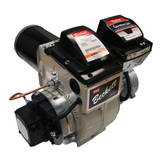
Oil burner
220-240v, 50/60hz
Hide thumbs
Also See for AF:
- Instruction manual (24 pages) ,
- Manual (24 pages) ,
- Instruction manual (8 pages)
Table of Contents
Advertisement
Quick Links
Download this manual
See also:
Instruction Manual
220-240V, 50/60Hz
Potential for Fire, Smoke and Asphyxiation Hazards
Incorrect installation, adjustment, or misuse of this burner could result in death, severe
personal injury, or substantial property damage.
To the Homeowner or Equipment Owner:
Please read and carefully follow all instructions
provided in this manual regarding your
responsibilities in caring for your heating
equipment.
Contact a professional, qualifi ed service agency for
installation, start-up or service work.
Save this manual for future reference.
RESIDENTIAL BURNERS
To the Professional, Qualifi ed Installer or Service Agency:
Please read and carefully follow all instructions provided
in this manual before installing, starting, or servicing this
burner or heating system.
The Installation must be made in accordance with all state
and local codes having jurisdiction.
Advertisement
Table of Contents

Related Manuals for Beckett AF


Summary of Contents for Beckett AF
- Page 1 RESIDENTIAL BURNERS 220-240V, 50/60Hz Potential for Fire, Smoke and Asphyxiation Hazards Incorrect installation, adjustment, or misuse of this burner could result in death, severe personal injury, or substantial property damage. To the Homeowner or Equipment Owner: To the Professional, Qualifi ed Installer or Service Agency: Please read and carefully follow all instructions Please read and carefully follow all instructions provided provided in this manual regarding your...
-
Page 2: Table Of Contents
Clearances to burner and appliance ..........Combustion chamber — Burner retrofi tting ........Your Beckett burner will provide years of Prepare the Burner ............8 effi cient operation if it is professionally Low Firing Rate Baffl e .............. -
Page 3: General Information
This manual contains information that applies to both AF and AFG burners. These burners may appear to be basically identical, but there are differences in design and performance. Please... - Page 4 ‘V1’ Head (AFG only) Firing Rate Range: 0.75 - 2.25 GPH 0.75 - 2.75 GPH Never try to convert an AF to an AFG or vice versa Input (Btu): 105,000 - 315,000 105,000 - 385,000 Any design alteration will: Certifi cations/Approvals Void UL Listing, if applicable.
- Page 5 Licensed or certifi ed to install and provide technical ○ When contacting Beckett for service information service to oil heating systems. — Please record the burner serial number (and have available when calling or writing). You will fi nd the...
-
Page 6: Inspect/Prepare Installation Site
Section: Inspect/Prepare Installation Site Inspect/Prepare Installation Site Inspect Chimney or Direct Vent System piece of broken tile wedged in the chimney should be removed. No other appliance connection should be made to Fire, Smoke & Asphyxiation the same fl ue pipe. Hazard The fl... -
Page 7: Combustion Air Supply
Refer to separate instruction sheet supplied with AF/AFG Adequate Combustion outside air kit for installation. This optional kit allows and Ventilation Air Supply combustion air to be piped directly to the burner (Beckett Required part number 51747). Failure to provide adequate air supply could... -
Page 8: Prepare The Burner
Section: Prepare the Burner Prepare the Burner Table 4. AFG Reduced Firing Rates (with LFRB) Burner head type Low Firing Rate Baffl e installed Low Firing Rate Baffl e up to 0.65 gph The AFG Low Firing Rate Baffl e (LFRB) reduces the F3 or L1 up to 0.85 gph air fl... -
Page 9: Check/Adjust Electrodes
Disconnect oil connector tube from nozzle line. Mounting dimensions Loosen the two screws securing igniter retaining When using the Beckett universal adjustable fl ange, clips and rotate both clips to release igniter mount the air tube at a 2° downward pitch unless baseplate. -
Page 10: Check/Adjust 'Z' Dimension - 'F' Heads
1-3/4 1-3/4 1-3/4 distance to the face of the head. A Beckett T501 gauge Note 1: 1-3/8 for dimension A less than 4”; 1-5/8 for dimension A from 4” through 4-1/2 “, may also be used. 2-13/32 for dimension A greater than 4-1/2”. - Page 11 A Beckett T501 gauge may also be used.
-
Page 12: Installing The Oil Tank And Supply System
Section: Mount Burner on Appliance Figure 7. – Mounting Burner in Appliance Figure 8. – Inside Tank Gravity Feed System If space between burner air tube and opening exceeds 1/2 inch, pack burner opening with ceramic fiber refractory. Tilt down 2° SK8745 Installing the Oil Tank and Supply System Oil Leak and Fire Hazard... -
Page 13: Wire Burner
Section: Wire Burner Wire burner Oil Supply Pressure Control Required Burner packaged with appliance Damage to the fi lter or pump seals could cause oil leakage and a fi re hazard. Electrical Shock Hazard The oil supply inlet pressure to the burner cannot exceed 3 psig. -
Page 14: Burner Controls
Section: Burner Controls Burner Controls Wiring GeniSys Model 7560 Control Explosion, Fire, Scald, and Burn Hazard Fire or Explosion Hazard All heating appliances must have HIGH LIMIT protection to interrupt electrical Can cause severe injury, death, or property power and shutdown the burner if operating damage. - Page 15 Section: Burner Controls Typical Burner Sequence of Operation for GeniSys 7560 Control. Refer to the appliance manufacturer’s wiring diagram for actual specifi cations. Pump Standby prime Trial for Lockout Valve-on delay ignition Ignition carryover Recycle Motor-off delay Standby: The burner is idle, waiting for a call for Ignition Carryover: Once fl...
-
Page 16: Reset Button Operation
Section: Burner Controls Figure 11a. – Interrupted ignition, valve-on delay Figure 11b. – Interrupted ignition, valve-on delay and only (no motor-off delay) motor-off delay SAFETY AND SAFETY AND OPERATING OPERATING LIMITS LIMITS THERMOSTAT THERMOSTAT IGNITER IGNITER IGNITER IGNITER L2 (IGN) L2 (IGN) MOTOR MOTOR... -
Page 17: Wire Burner
Cad Cell Resistance Measurement Heavy Smoke Hazard ○ If the Beckett 7560 control is equipped with the Failure to prime the pump properly could result in GeniSys Display Module, part 52067U, the cad cell unstable combustion, hot gas puff-back and heavy resistance can be selected and read on the LCD smoke. -
Page 18: Startup / Checkout
Section: Start-up Burner/Set Combustion ○ Always verify the control functions according to all At fl ame loss, the control will enter Recycle specifi cations before leaving the installation site. mode. Verify that the green light is fl ashing. The control will remain in Recycle for 60 seconds. ○... -
Page 19: Perform Regular Maintenance
Section: Perform Regular Maintenance Step 4: Recheck smoke level. It should be Zero. replacing any that are cracked or chipped. This procedure provides a margin of □ Check electrode tip settings. Replace electrodes if reserve air to accommodate variable tips are rounded. conditions. - Page 20 Referring to the fi gure below, slide the new blower wheel onto the shaft. ○ Use a feeler gauge to set the wheel-to-motor gap, as shown below. (AF = 0.125 +1/64 inch, AFG = 0.030 +1/64 inch) ○ Slide blower wheel toward motor until it contacts feeler gauge.
-
Page 21: Replacement Parts
Section: Burner Controls Replacement Parts ► 240V AFG Burner Manual... - Page 23 240V AFG Burner Manual...
-
Page 24: Limited Warranty Information
The R. W. BECKETT CORPORATION (“Beckett”) warrants to persons who purchase its “Products” from Beckett for resale, or for incorporation into a product for resale (“Customers”), that its equipment is free from defects in material and workmanship. To qualify for warranty benefi ts, products must be installed by a qualifi...