Table of Contents
Advertisement
Potential for Fire, Smoke and Asphyxiation Hazards
Incorrect installation, adjustment, or misuse of this burner could result in death, severe
personal injury, or substantial property damage.
To the Homeowner or Equipment Owner:
Please read and carefully follow all instructions
provided in this manual regarding your
responsibilities in caring for your heating
equipment.
Contact a professional, qualifi ed service agency for
installation, start-up or service work.
Save this manual for future reference.
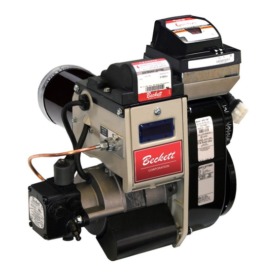
RESIDENTIAL BURNERS
To the Professional, Qualifi ed Installer or Service Agency:
Please read and carefully follow all instructions provided
in this manual before installing, starting, or servicing this
burner or heating system.
The Installation must be made in accordance with all state
and local codes having jurisdiction.
Advertisement
Table of Contents

Related Manuals for Beckett AFII


Summary of Contents for Beckett AFII
- Page 1 Potential for Fire, Smoke and Asphyxiation Hazards Incorrect installation, adjustment, or misuse of this burner could result in death, severe personal injury, or substantial property damage. To the Homeowner or Equipment Owner: Please read and carefully follow all instructions provided in this manual regarding your responsibilities in caring for your heating equipment.
-
Page 3: Table Of Contents
Your Beckett burner will provide years of effi cient operation if it is professionally installed and maintained by a qualifi ed service technician. -
Page 4: General Information
Never attempt to burn any fuel not specifi ed and approved for use in this burner. Never restrict the air inlet openings to the burner or the combustion air ventilation openings in the room. -
Page 5: Inspect/Prepare Installation Site
Fire Hazard. Do NOT operate the burner beyond specifi cations outlined in the following Table. For applications beyond these limits, consult Beckett Technical Service at 1-800-645-2876. NOTE: Some packaged appliances with burners may be agency listed as a unit to operate beyond these limits. - Page 6 fl ue gases creating sulphuric acid. The acid will attack the chimney mortar, brick and clay liners causing corrosion, deterioration and blockage of the chimney. Firing rate range (gph)Min-Max AFII 85 AFII 100 AFII 150 0.4-0.85 gph 0.65-1.00 gph 0.75-1.35 gph...
-
Page 7: Combustion Air Supply Information
○ AFII burners are equipped with a removable air inlet to allow use of a 4” duct to supply outside air for combustion. Do not exceed 50 equivalent feet. Allow 6 feet for each elbow. -
Page 8: Prepare The Burner
fi ttings. Never use compression fi ttings. Note: to determine the proper fuel line size, refer to the fuel pump manufacturer’s instructions provided with the burner. Refer to Figure 4 or Figure 5 for typical installation layouts. Always install fi ttings in accessible locations. To avoid vibration noise, fuel lines should not run against the appliance or ceiling joists. -
Page 9: Mount Burner On Appliance
Mount Burner on Appliance Verify that the air tube installed on the burner provides the correct insertion depth. Refer to Figure 6. Figure 6. – Mounting Burner in Appliance The end of the air tube should normally be 1/4” back from the inside wall of the combustion chamber. -
Page 10: Burner Controls
Incorrect Wiring Will Result in Improper Control Operation GeniSys wiring label colors may not match the wire colors of the burner or other manufacturers’ controls. The GeniSys Control should be wired according to the appliance manufacturer’s instructions. Wiring Connections... -
Page 11: Burner Sequence Of Operation
Motor-Off Delay, if applicable, or it is shut down and sent to Standby. Recycle: If the fl ame is lost while the burner is fi ring, the control shuts down the burner, enters a 60 second recycle delay, and repeats the ignition sequence. -
Page 12: Reset Button Operation
Table 2 explains what action the control will take when the reset button is pressed for different lengths of time during the various burner operating states. Table 2 - Reset Button Operation If the burner is in the below state: (press < 1 second) - Page 13 Figure 9 - Typical Burner Wiring & Burner Sequence of Operation for R7184P Control. Refer to the appliance manufacturer’s wiring diagram for actual specifi cations. STANDBY. The burner is idle, waiting for a call for heat. When a call for heat is initiated, there is a 3- 10 second delay while the control performs a safe start check.
-
Page 14: Wire Burner
Note that i f the thermostat short cycles or operates improperly, it may require an isolation relay for proper operation. The Beckett A/C Ready Kit (part no. 51950U) provides this function. Wiring instructions are included with the A/C Ready Kit. -
Page 15: Perform Regular Maintenenance
○ High Effi ciency/Positive Pressure Appliances; also vary from traditional appliances (see manufacturer’s recommendations). Follow these four steps to properly adjust the burner: Step 1: Adjust the air dial until a trace of smoke is achieved. Step 2: At the trace of smoke level, measure the CO 2 (or O 2 ) . -
Page 16: Shutting The Burner Off
Turn off all electric power to the burner. Note: There could be more than one disconnect switch. Removing Nozzle Line for Service Correct Nozzle and Flow Rate Required Incorrect nozzles and fl... -
Page 17: Check/Adjust Electrodes
For installation or replacement of a blower wheel, insure that there is a space between the blower wheel and the motor face of 0.062” (1/16” + 1/64”). Refer to Figure 12. AFII Burner Manual Section: Perform Regular Maintenance Figure 11a. Electrode Settings-HLX Air Tube Combinations ”. - Page 18 Section: Perform Regular Maintenance HLX Firing Rate Stop AFII 85 AFII 100 Screw 0.40-0.65 0.5-0.65 0.6-0.75 0.65-0.80 0.60-0.75 0.65-0.90 0.75-0.95 0.70-0.85 0.85-1.00 0.95-1.10 HLX Air Dial Setting Firing Rate AFII 85 AFII 100 @ 140 psig 0.40-0.65 0.60-0.75 0.70-0.85 0.75-1.00 0.95-1.20...
-
Page 19: Replacement Parts
2184404U Splined Nut 31658 Dial, Air Adjustment (UL approved) Specify* *Contact your Beckett representative for part number and pricing. 51671U **Contact your Beckett representative for available pre and post time settings. 51672U 51685 51805U 51485 Section: Replacement Parts Kit No. -
Page 20: Limited Warranty Information
The R. W. BECKETT CORPORATION (“Beckett”) warrants to persons who purchase its “Products” from Beckett for resale, or for incorporation into a product for resale (“Customers”), that its equipment is free from defects in material and workmanship. To qualify for warranty benefi ts, products must be installed by a qualifi...