
Related Manuals for Carrier 69NT40-561-019


Summary of Contents for Carrier 69NT40-561-019
- Page 1 Container Refrigeration OPERATIONS AND SERVICE 69NT40-561-019 Evergreen Container Refrigeration Units T-359 Rev B...
- Page 3 OPERATIONS AND SERVICE 69NT40-561-019 Evergreen Container Refrigeration Units © 2017 Carrier Corporation Printed in USA June 2017 ●...
- Page 5 TABLE OF CONTENTS PARAGRAPH NUMBER PAGE SAFETY SUMMARY ..............1–1 GENERAL SAFETY NOTICES .
-
Page 6: Table Of Contents
SAFETY AND PROTECTIVE DEVICES ..........3–8 REFRIGERATION CIRCUIT . - Page 7 4.7.6 Sampling Type (dCF05 & dCF06) ......... . . 4–19 4.7.7 Alarm Configuration (dCF07 - dCF10) .
- Page 8 7.3.1 Service Connections ............7–2 7.3.2 Pumping Down the Unit .
- Page 9 LIST OF ILLUSTRATIONS FIGURE NUMBER Page Figure 3.1 Refrigeration Unit - Front Section ..........3–1 Figure 3.2 Evaporator Section .
- Page 10 LIST OF TABLES TABLE NUMBER Page Table 3–1 Safety and Protective Devices ........... . 3–8 Table 4–1 Keypad Function .
-
Page 11: Safety Summary
SECTION 1 SAFETY SUMMARY GENERAL SAFETY NOTICES The following general safety notices supplement specific warnings and cautions appearing elsewhere in this man- ual. They are recommended precautions that must be understood and applied during operation and maintenance of the equipment covered herein. The general safety notices are presented in the following three sections labeled: First Aid, Operating Precautions and Maintenance Precautions. - Page 12 The statements listed below are applicable to the refrigeration unit and appear elsewhere in this manual. These recommended precautions must be understood and applied during operation and maintenance of the equipment covered herein. DANGER Never use air for leak testing. It has been determined that pressurized, mixtures of refrigerant and air can undergo combustion when exposed to an ignition source.
- Page 13 WARNING Always turn OFF the unit circuit breakers (CB-1 and CB-2) and disconnect main power supply before working on moving parts. WARNING Installation requires wiring to the main unit circuit breaker, CB1. Make sure the power to the unit is off and power plug disconnected before beginning installation. CAUTION Charge receiver according to nameplate specifications to ensure optimal unit performance.
- Page 14 CAUTION Allowing the scroll compressor to operate in reverse for more than two minutes will result in internal compressor damage. Turn the start-stop switch OFF immediately. CAUTION To prevent trapping liquid refrigerant in the manifold gauge set be sure set is brought to suc- tion pressure before disconnecting.
-
Page 15: Introduction
18 and 24 volts, single phase. The controller is a Carrier Transicold Micro-Link 3 microprocessor. The controller will operate automatically to select cooling, holding or heating as required to maintain the desired set point temperature within very close limits. The unit may also be equipped with an electronic temperature recorder. -
Page 16: Dehumidification
2.4.2 Dehumidification The unit is fitted with a humidity sensor. This sensor allows setting of a humidity set point in the controller. In dehu- midification mode, the controller will operate to reduce internal container moisture level. 2.4.3 USDA The unit is supplied with fittings for additional temperature probes, which allow recording of USDA Cold Treatment data by the integral DataCORDER function of the Micro-Link refrigeration controller. -
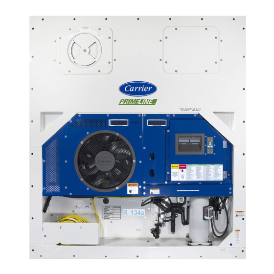
Page 17: Figure 3.1 Refrigeration Unit - Front Section
SECTION 3 DESCRIPTION GENERAL DESCRIPTION 3.1.1 Refrigeration Unit - Front Section The unit is designed so that the majority of the components are accessible from the front (see Figure 3.1). The unit model number, serial number and parts identification number can be found on the serial plate to the left of the receiver on the back wall of the condenser section. -
Page 18: Figure 3.2 Evaporator Section
3.1.3 Evaporator Section The evaporator section (Figure 3.2) contains the return temperature sensor, humidity sensor, electronic expansion valve, dual speed evaporator fans (EM1 and EM2), evaporator coil and heaters, defrost temperature sensor, heat termination thermostat and evaporator temperature sensors (ETS1 and ETS2). The evaporator fans circulate air through the container by pulling it in the top of the unit, directing it through the evaporator coil, where it is heated or cooled, and discharging it at the bottom. -
Page 19: Figure 3.3 Compressor Section
3.1.4 Compressor Section The compressor section (Figure 3.3) includes the compressor, digital unloader valve (DUV), high pressure switch, discharge pressure transducer (DPT), evaporator pressure transducer (EPT) and the suction pressure transducer (SPT). The supply temperature sensor, supply recorder sensor and ambient sensor are located to the left of the compressor. Figure 3.3 Compressor Section COMPRESSOR COVER REMOVED FOR CLARITY... -
Page 20: Figure 3.4 Air-Cooled Condenser Section
3.1.5 Air-Cooled Condenser Section The air-cooled condenser section (Figure 3.4) consists of the condenser fan, condenser coil, receiver, liquid line service valve, filter drier, fusible plug, economizer, economizer expansion valve, economizer solenoid valve (ESV), and sight glass/moisture indicator. The condenser fan pulls air through the bottom of the coil and discharges it horizontally through the con denser fan grille. Figure 3.4 Air-Cooled Condenser Section 1. -
Page 21: Figure 3.5 Control Box Section
3.1.6 Control Box Section The control box (Figure 3.5) includes: the manual operation switches, circuit breaker (CB-1), compressor, fan and heater contactors, control power transformer, fuses, key pad, display module, current sensor module, controller module and the communications interface module. 3.1.7 Communications Interface Module The optional communications interface module is a slave module that allows communication with a master central... -
Page 22: Refrigeration System Data
REFRIGERATION SYSTEM DATA Model Number ZMD26KVE-TFD-274 Weight (With Oil) 42.9 kg (95 lb) a. Compressor/Motor Assembly Approved Oil Uniqema Emkarate RL-32-3MAF Oil Charge 1774 ml (60 ounces) Verify at -18C b. Electronic Expansion Valve (0F) container box 4.4 to 6.7C (8 to 12F) Superheat (Evaporator) temperature Verify at -18C... - Page 23 d. Evaporator Coil Number of Heaters Heater, Standard Rating 750 watts +/- 5% @ 230 VAC Resistance (cold) 72 ohms +/- 5% Type Sheath e. Evaporator Coil Number of Heaters Heater, Straight Rating 750 watts +/- 7.5% @ 460 VAC Resistance (cold) 282 ohms +/-7.5% Type...
-
Page 24: Safety And Protective Devices
m. Humidity Sensor Orange wire Power Red wire Output Brown wire Ground Input voltage 5 VDC Output voltage 0 to 3.3 VDC Output voltage readings verses relative humidity (RH) percentage: 0.99 V 1.65 V 2.31 V 2.97 V SAFETY AND PROTECTIVE DEVICES Unit components are protected from damage by safety and protective devices listed in Table 3–1. -
Page 25: Refrigeration Circuit
REFRIGERATION CIRCUIT 3.5.1 Standard Operation Starting at the compressor, (see Figure 3.6) the suction gas is compressed to a higher pressure and temperature. The refrigerant gas flows through the discharge line and continues into the air-cooled condenser. When operating with the air-cooled condenser active, air flowing across the coil fins and tubes cools the gas to saturation tempera- ture. -
Page 26: Figure 3.6 Refrigeration Circuit Schematic - Standard Operation
Figure 3.6 Refrigeration Circuit Schematic - Standard Operation STANDARD OPERATION WITH RECEIVER COMBO EVAPORATOR ETS1 AND 2 ELECTRONIC EXPANSION VALVE CONDENSER DIGITAL UNLOADER VALVE ECON. DISCHARGE SENSING TEMPERATURE BULB SENSOR ECONOMIZER SOLENOID DISCHARGE VALVE SERVICE VALVE SIGHT ECONOMIZER GLASS EVAPORATOR PRESSURE FILTER TRANSDUCER... -
Page 27: Microprocessor
SECTION 4 MICROPROCESSOR TEMPERATURE CONTROL MICROPROCESSOR SYSTEM The temperature control Micro-Link 3 microprocessor system (see Figure 4.1) consists of a keypad, display mod- ule, the control module (controller) and interconnecting wiring. The controller houses the temperature control soft- ware and the DataCORDER software. The temperature control software functions to operate the unit components as required to provide the desired car go temperature and humidity. -
Page 28: Keypad
4.1.1 Keypad Figure 4.2 Keypad Table 4–1 Keypad Function FUNCTION CODE Accesses function codes. SELECT Displays Pre-trip selection menu. PRE TRIP CODE Discontinues Pre-trip in progress. SELECT TRIP Displays alarm list and clears the ALARM LIST alarm queue. Displays selected defrost mode. MANUAL ALARM Depress and hold the MANUAL DE-... -
Page 29: Controller
5. Supply - Yellow LED: Energized when the supply air probe is used for control. When this LED is illuminated, the temperature displayed in the AIR TEMPERATURE display is the reading at the supply air probe. This LED will flash if dehumidification or humidification is enabled. 6. -
Page 30: Controller Software
Figure 4.4 Control Module EN12830 CONTROLLER With CARRIER Micro-Link3 DataCORDER S/N: 0491162 REV 5147 YYWW: 1035 12-00579-00 T B C1 59980 1. Mounting Screw 5. Fuses 2. Micro-Link 3 Control/DataCORDER Module 6. Control Circuit Power Connection 3. Connectors 7. Software Programming Port 4. -
Page 31: Controller Sequence And Modes Of Operation
To access the function codes, perform the following: a. Press the CODE SELECT key, then press an arrow key until the left window displays the desired code number. b. The right window will display the value of this item for five seconds before returning to the normal display mode. c. -
Page 32: Perishable Set Point Temperature Control
In order to achieve economy mode, a perishable set point must be selected prior to activation. When economy mode is active, the evaporator fans will be controlled as follows: At the start of each cooling or heating cycle, the evaporator fans will run in high speed for three minutes. They will then be switched to low speed any time the supply air temperature is within +/- 0.2°C (0.36°F) of the set point and the return air temperature is less than or equal to the supply air temperature +3°C (5.4°F). -
Page 33: Perishable Mode Cooling - Sequence Of Operation
4.3.7 Perishable Mode Cooling - Sequence of Operation NOTE In the Standard Perishable Mode of Operation, the evaporator motors run in high speed. In the Econ- omy Perishable Mode, the fan speed is varied. With supply air temperature above set point and decreasing, the unit will cool with the condenser fan motor (CF), compressor motor (CH), evaporator fan motors (EF) energized and the COOL light illuminated. -
Page 34: Perishable Mode - Dehumidification
4.3.10 Perishable Mode - Dehumidification The dehumidification mode is provided to reduce the humidity levels inside the container. The mode is activated when a humidity value is set at function code Cd33. The display module SUPPLY LED will flash ON and OFF every second to indicate that the dehumidification mode is active. -
Page 35: Frozen Mode - Temperature Control
4.3.12 Frozen Mode - Temperature Control When in the frozen mode, the controller maintains the return air temperature at or below set point, the RETURN indicator light will be illuminated on the display module and the default reading on the display window will be the return air probe reading. -
Page 36: Frozen Mode Cooling - Sequence Of Operation
4.3.15 Frozen Mode Cooling - Sequence of Operation a. When the return air temperature is above set point and decreasing, the unit will transition to economized cooling with the condenser fan motor (CF), compressor motor (CH), economizer solenoid valve (ESV), low speed evaporator fan motors (ES) energized and the COOL light illuminated. -
Page 37: Defrost Interval
4.3.17 Defrost Interval Controller function code Cd27 sets two modes for defrost initiation, either user-selected timed intervals or auto- matic control. The user-selected values are 3, 6, 9, 12, 24 hours, AUTO, or PuLs. Some units may be configured to allow defrost to be disabled altogether. -
Page 38: Defrost Pulsing
Defrost may be initiated any time the defrost temperature sensor reading falls below the controller defrost termina- mion thermostat set point. Defrost will terminate when the defrost temperature sensor reading rises above the defrost termination thermostat set point. The defrost termination thermostat is not a physical component. It is a controller set- ting that acts as a thermo stat, “closing”... -
Page 39: Protection Modes Of Operation
During defrost the evaporator fans will cycle ON Low Speed once DTS reaches 0°C (32°F) and STS is below -5°C (23°F). Once the evaporator fans cycle ON the controller will monitor STS at 1 second intervals and calculate the difference between the current STS reading and the previous STS reading. If STS becomes warmer that -5°C (23°F) or the calculated difference of STS remains below 0.1°C (0.18°F) for 10 consecutive readings or DTS reaches 20°C (68°F), the evaporator fans will turn off for 3 minutes. -
Page 40: Controller Alarms
CONTROLLER ALARMS Alarm display is an independent controller software function. If an operating parameter is outside of expected range or a component does not return the correct signals back to the controller, an alarm is generated. A listing of the alarms is provided in Table 4–6. -
Page 41: Datacorder
4.7.1 Description The Carrier Transicold “DataCORDER” software is integrated into the controller and serves to eliminate the tem- perature recorder and paper chart. The DataCORDER functions may be accessed by keypad selections and viewed on the display module. The unit is also fitted with interrogation connections (see Figure 4.1) which may be... -
Page 42: Datacorder Software
A list of the data points available for recording follows. Changing the configuration to generic and selecting which data points to record may be done using the Carrier Transicold Data Retrieval Program. -
Page 43: Logging Interval (Dcf03)
4.7.4 Logging Interval (dCF03) The user may select four different time intervals between data recordings. Data is logged at exact intervals in accordance with the real time clock. The clock is factory set at Greenwich Mean Time (GMT). 4.7.5 Thermistor Format (dCF04) The user may configure the format in which the thermistor readings are recorded. -
Page 44: Figure 4.11 Standard Configuration Download Report
Figure 4.11 Standard Configuration Download Report Raw Data Report for ABC1234567 May 31, 2003 to Jun 04, 2003 System Configuration at the Time of Interrogation: Interrogated On Sept 05, 2003 Extracted by DataLine Rev 1.0.0 Controller Software: 5120 Controller Serial #: 04163552 Bill of Lading #: 1 Origin: Origin Date:... -
Page 45: Sampling Type (Dcf05 & Dcf06)
Table 4–3 DataCORDER Standard Configurations STANDARD CONFIG DESCRIPTION 2 sensors 2 thermistor inputs (supply & return) (dCF02=2) 5 sensors 2 thermistor inputs (supply & return) (dCF02=5) 3 USDA thermistor inputs 2 thermistor inputs (supply & return) 6 sensors 3 USDA thermistor inputs (dCF02=6) 1 humidity input 9 sensors... -
Page 46: Pre-Trip Data Recording
2. PC communication port(s) unavailable or mis-assigned. 3. Chart Recorder Fuse (FCR) blown. Configuration identification for the models covered herein may be obtained on the Container Products Group Infor- mation Center by authorized Carrier Transicold Service Centers. a. DataReader The Carrier Transicold Data Reader (see Figure 4.12) is a simple to operate handheld device designed to extract... -
Page 47: Usda Cold Treatment
In response to the demand to replace fumigation with this environmentally sound process, Carrier has integrated Cold Treatment capability into its microprocessor system. These units have the ability to maintain supply air tem- perature within one quarter degree Celsius of set point and record minute changes in product temperature within the DataCORDER memory, thus meeting USDA criteria. -
Page 48: Datacorder Alarms
d. Place the three probes. The probes are placed into the pulp of the product (at the locations defined in the following table) as the product is loaded. Sensor 1 Place in pulp of the product located next to the return air intake. Place in pulp of the product five feet from the end of the load for 40 foot containers, or three feet from the end of the load for 20 foot con- Sensor 2... -
Page 49: Iso Trip Header
4.7.15 ISO Trip Header DataLINE provides the user with an interface to view/ modify current settings of the ISO trip header through the ISO Trip Header screen. The ISO Trip Header screen is displayed when the user clicks on the “ISO Trip Header” button in the “Trip Func- tions”... - Page 50 Table 4–4 Controller Configuration Variables (Continued) CONFIG # TITLE DEFAULT OPTION CnF45 Low Humidity Enabled UP, LOW, CnF47 Fresh Air Vent Position Sensor CUStOM CnF49 DataCORDER Configuration Restore CnF50 Enhanced Bulb Mode Selection Bulb, dEHUM CnF51 Timed Defrost Disable 0-out, 1-in CnF52 Oil Return Algorithm 0-out, 1-in...
-
Page 51: Table 4-5 Controller Function Codes
Table 4–5 Controller Function Codes CODE # TITLE DESCRIPTION NOTE If the function is not applicable, the display will read “-----” Display Only Functions Displays the DUV percent closed. The right display reads 100% when the valve is ful- Digital Unloader Cd01 ly closed. - Page 52 Table 4–5 Controller Function Codes (Continued) CODE # TITLE DESCRIPTION This code checks the Controller/DataCORDER battery pack. While the test is run- ning, “btest” will flash on the right display, followed by the result. “PASS” will be dis- played for battery voltages greater than 7.0 volts. “FAIL” will be displayed for battery Cd19 Battery Check voltages between 4.5 and 7.0 volts, and “-----”...
- Page 53 Table 4–5 Controller Function Codes (Continued) CODE # TITLE DESCRIPTION If all of the control sensors are out of range (alarm code AL26) or there is a probe cir- cuit calibration failure (alarm code AL27), the unit will enter the shutdown state de- fined by this setting.
- Page 54 Table 4–5 Controller Function Codes (Continued) CODE # TITLE DESCRIPTION This code, as with function code Cd36, is used in conjunction with bulb mode and de- Defrost humidification. If bulb mode is active, this code allows the user to change the tem- Termination perature above which defrost will terminate.
- Page 55 Table 4–5 Controller Function Codes (Continued) CODE # TITLE DESCRIPTION Code 50 allows selection of CCPC mode. The user can press ENTER, then arrow keys, then ENTER again to enable (On) or suspend (OFF) CCPC mode. If CCPC op- eration is On, it may be suspended due to one of the following conditions: “SEtPt”...
-
Page 56: Figure 4.13 Alarm Troubleshooting Sequence
Table 4–5 Controller Function Codes (Continued) CODE # TITLE DESCRIPTION CD60 contains a selectable temperature range used to determine the engagement Evaporator Fan point of the Evaporator Fan Pulsing logic. Default setting is -18.1°C. The user may Pulsing change the temperature by pressing enter, then scrolling to the desired temperature Cd60 Temperature using either arrow key. -
Page 57: Table 4-6 Controller Alarm Indications
Table 4–6 Controller Alarm Indications CODE # CAUSE COMPONENTS TROUBLESHOOTING CORRECTIVE ACTIONS Superheat has re- Electronic Expan- Check the operation of Replace EEV if mained below 1.66C sion Valve (EEV) the EEV using Cd41. defective. (3F) degrees for five Evaporator Tem- Verify accuracy of tem- minutes continuously perature Sen-... - Page 58 Table 4–6 Controller Alarm Indications CODE # CAUSE COMPONENTS TROUBLESHOOTING CORRECTIVE ACTIONS Resetting the unit may cor- Power cycle the unit. rect problem, monitor the unit. Check unit wiring. Confirm pressure read- ings during start-up; suc- Wiring Correct wiring. tion pressure should AL14 decrease and discharge Controller is unable to...
- Page 59 Table 4–6 Controller Alarm Indications CODE # CAUSE COMPONENTS TROUBLESHOOTING CORRECTIVE ACTIONS Controller will attempt re- start every 20 minutes Resume normal and deactivate the alarm operation. if successful. Confirm accurate DPT Discharge Pres- Compressor has at- pressure readings, refer Replace DPT if sure Transducer tempted to start in both...
- Page 60 Table 4–6 Controller Alarm Indications CODE # CAUSE COMPONENTS TROUBLESHOOTING CORRECTIVE ACTIONS Ensure the Discharge Open the Discharge Ser- Service Valve is fully Restrictions in the vice Valve as needed. open. refrigeration system. Check the unit for air flow Clean or remove any restrictions.
- Page 61 Table 4–6 Controller Alarm Indications CODE # CAUSE COMPONENTS TROUBLESHOOTING CORRECTIVE ACTIONS Monitor unit, if alarm re- Shut down unit discon- mains active or is repeti- AL24 nect power, & check re- tive replace the Compressor internal Compressor Compressor sistance of compressor compressor at the next protector (IP) is open.
- Page 62 Table 4–6 Controller Alarm Indications CODE # CAUSE COMPONENTS TROUBLESHOOTING CORRECTIVE ACTIONS Pressing the ENTER key If action is successful (all when “CLEAr” is dis- alarms are inactive), alarm played will result in an at- 51 will be reset. AL51 tempt to clear the alarm.
- Page 63 Table 4–6 Controller Alarm Indications CODE # CAUSE COMPONENTS TROUBLESHOOTING CORRECTIVE ACTIONS AL60 Defrost Tem- Failure of the Defrost Test the DTS; refer to Replace the DTS if defec- Defrost Tempera- perature Temperature Sensor Sensor Checkout Proce- tive, refer to Sensor Re- ture Sensor (DTS) Sensor (DTS) to open.
- Page 64 Table 4–6 Controller Alarm Indications CODE # CAUSE COMPONENTS TROUBLESHOOTING CORRECTIVE ACTIONS Make sure the humidity sensor is properly con- AL67 nected in the socket. Humidity Sensor (HS) Humidity Sensor Monitor, replace HS if Humidity reading out of range. (HS) alarm persists.
- Page 65 Table 4–6 Controller Alarm Indications CODE # CAUSE COMPONENTS TROUBLESHOOTING CORRECTIVE ACTIONS The controller performs self-check routines. If an internal failure occurs, an “ERR”alarm will appear on the display. This is an indication the controller needs to be re placed. ERROR DESCRIPTION Indicates that the controller working...
-
Page 66: Table 4-7 Controller Pre-Trip Test Codes
Table 4–7 Controller Pre-trip Test Codes CODE # TITLE DESCRIPTION NOTE “Auto” or “Auto1” menu includes the: P0, P1, P2, P3, P4, P5, P6 and rSLts. “Auto2” menu includes P0, P1, P2, P3, P4, P5, P6, P7, P8, P9, P10 and rSLts. “Auto3” menu includes P0, P1, P2, P3, P4, P5, P6, P7 and P8. - Page 67 Table 4–7 Controller Pre-trip Test Codes (Continued) CODE # TITLE DESCRIPTION Requirements: For units equipped with secondary supply probe only. Pass/Fail Criteria: The temperature difference between supply temperature sen- sor (STS) and supply recorder sensor (SRS) probe is compared. P5-1 Supply Probe Test If this test fails, “P5-1”...
- Page 68 Table 4–7 Controller Pre-trip Test Codes (Continued) CODE # TITLE DESCRIPTION Discharge If alarm 64 is activated any time during the first 45 second period of P6-0 Thermistor Test Step 1, the test fails. Alarm is activated if suction temperature is outside of the valid range of -60C (- Suction P6-1 76F) to 150C (302F) any time during the first 45 second period of Step 1, the...
- Page 69 Table 4–7 Controller Pre-trip Test Codes (Continued) CODE # TITLE DESCRIPTION NOTE This test is skipped if the sensed ambient temperature is less than 7C (45F), the return air temperature is less than -17.8C (0F), the water pressure switch is open or the condenser fan switch is open.
- Page 70 Table 4–7 Controller Pre-trip Test Codes (Continued) CODE # TITLE DESCRIPTION Requirements: Test P8-1 must pass for this test to execute. This test is skipped if the DataCORDER is not configured or not available. Setup: A 15-minute timer is started. The unit will be required to minimize control temperature error (supply temperature minus set point) until the timer expires.
-
Page 71: Table 4-8 Datacorder Function Code Assignments
Table 4–8 DataCORDER Function Code Assignments NOTE Inapplicable Functions Display “-----” To Access: Press ALT. MODE key CODE # TITLE DESCRIPTION Recorder Supply Current reading of the supply recorder sensor. Temperature Recorder Return Current reading of the return recorder sensor. Temperature USDA 1,2,3 dC3-5... -
Page 72: Table 4-9 Datacorder Pre-Trip Result Records
Table 4–9 DataCORDER Pre-trip Result Records TEST # TITLE DATA Heater On Pass/Fail/Skip Result, Change in current for Phase A, B and C Heater Off Pass/Fail/Skip Result, Change in currents for Phase A, B and C Condenser Fan On Pass/Fail/Skip Result, Water pressure switch (WPS) - Open/ Closed, Change in currents for Phase A, B and C Condenser Fan Off Pass/Fail/Skip Result, Change in currents for Phase A, B and C... -
Page 73: Table 4-10 Datacorder Alarm Indications
Table 4–10 DataCORDER Alarm Indications To Access: Press ALT. MODE key CODE # TITLE DESCRIPTION The supply recorder sensor reading is outside of the range of -50C to 70C (-58F to +158F), or the probe check logic has determined there is a fault Recorder Supply with this sensor. -
Page 75: Operation
SECTION 5 OPERATION INSPECTION (BEFORE LOADING) WARNING Beware of unannounced starting of the evaporator and condenser fans. The unit may cycle the fans and compressor unexpectedly as control requirements dictate. a. Check inside for the following: 1. Check channels or “T” bar floor for cleanliness. Channels must be free of debris for proper air circulation. 2. -
Page 76: Upper Fresh Air Makeup Vent
5.3.1 Upper Fresh Air Makeup Vent Two slots and a stop are designed into the Upper Fresh Air disc for air flow adjustments. The first slot allows for a 0 to 30% air flow; the second slot allows for a 30 to 100% air flow. To adjust the percentage of air flow, loosen the wing nut and rotate the disc until the desired percentage of air flow matches with the arrow. -
Page 77: Connect Remote Monitoring Receptacle
CONNECT REMOTE MONITORING RECEPTACLE If remote monitoring is required, connect remote monitor plug at unit receptacle. When the remote monitor plug is connected to the remote monitoring receptacle, the following remote circuits are energized: CIRCUIT FUNCTION Sockets B to A Energizes remote cool light Sockets C to A Energizes remote defrost light... -
Page 78: Complete Inspection
DataCORDER a. Check and, if required, set the DataCORDER Configuration in accordance with desired recording parame- ter. Refer to Section 4.7.3. b. Enter a “Trip Start.” To enter a “Trip Start,” do the fol lowing: 1. Depress the ALT MODE key. When the left display shows, dC, depress the ENTER key. 2. -
Page 79: Observe Unit Operation
a. Press the PRE-TRIP key. This accesses a test selection menu. b. TO RUN AN AUTOMATIC TEST: Scroll through the selections by pressing the UP ARROW or DOWN ARROW keys to display AUTO, AUTO 1, AUTO 2, or AUTO 3 as desired, then press the ENTER key. 1. - Page 80 a. Probe Diagnostic Logic In the perishable mode of operation, both pairs of supply and return probes are monitored for probe disagreement. Probe disagreement is considered a difference of 0.5C (0.9F) or greater between the supply air sensors and/or a difference of 2.0C (3.6F) between the return air sensors.
-
Page 81: Troubleshooting
SECTION 6 TROUBLESHOOTING REMEDY/ CONDITION POSSIBLE CAUSE REFERENCE SECTION UNIT WILL NOT START OR STARTS THEN STOPS External power source OFF Turn on No power to unit Start-Stop switch OFF or defective Check Circuit breaker tripped or OFF Check Circuit breaker OFF or defective Check Control transformer defective Replace... -
Page 82: Unit Runs But Has Insufficient Cooling
REMEDY/ CONDITION POSSIBLE CAUSE REFERENCE SECTION Shortage of refrigerant Evaporator coil covered with ice Evaporator coil plugged with debris Evaporator fan(s) rotating backwards 7.9/7.10 Air bypass around evaporator coil Check Controller set too low Reset Compressor service valves or liquid line Open valves Refrigeration system shutoff valve partially closed... -
Page 83: Unit Will Not Terminate Heating
REMEDY/ CONDITION POSSIBLE CAUSE REFERENCE SECTION Heater(s) defective Heater contactor or coil defective Replace Evaporator fan motor(s) defective or rotating backwards 7.9/7.10 Evaporator fan motor contactor defective Replace Unit will not heat or has insufficient heat Controller malfunction Defective wiring Replace Loose terminal connections Tighten... -
Page 84: Abnormal Noise Or Vibrations
REMEDY/ CONDITION POSSIBLE CAUSE REFERENCE SECTION Incorrect software and/or controller configuration Check Failed suction pressure transducer (SPT) or evaporator pressure Replace transducer (EPT) Suction service valve partially closed Open Filter drier partially plugged Low refrigerant charge Low suction pressure No evaporator air flow or restricted air flow Excessive frost on evaporator coil Evaporator fan(s) rotating backwards 7.10.3... -
Page 85: 6.11 Electronic Expansion Valve Malfunction
REMEDY/ CONDITION POSSIBLE CAUSE REFERENCE SECTION 6.11 ELECTRONIC EXPANSION VALVE MALFUNCTION Incorrect software and/or controller configuration Check Failed suction pressure transducer (SPT), Replace or evaporator pressure transducer (EPT) Suction service valve partially closed Open Filter drier partially plugged Low refrigerant charge Low suction pressure No evaporator air flow or restricted air flow Excessive frost on evaporator coil... -
Page 86: 6.13 Abnormal Temperatures
REMEDY/ CONDITION POSSIBLE CAUSE REFERENCE SECTION 6.13 ABNORMAL TEMPERATURES Condenser coil dirty Condenser fan rotating backwards Condenser fan inoperative Refrigerant overcharge or noncondensibles Discharge service valve partially closed Open Electronic expansion valve (EEV) control malfunction Replace High discharge temperature Failed suction pressure transducer (SPT), Replace or evaporator pressure transducer (EPT) Discharge temperature sensor drifting high... -
Page 87: Service
A R-134a manifold gauge/hose set with self-sealing hoses (Figure 7.2) is required for service of the models cov- ered within this manual. The manifold gauge/ hose set is available from Carrier Transicold. (Carrier Transicold part number 07-00294-00, which includes items 1 through 6, Figure 7.2.) To perform service using the manifold gage/... -
Page 88: Refrigeration System Service-Units With Standard Piping
Preparing Manifold Gauge/Hose Set For Use: If the manifold gauge/hose set is new or was exposed to the atmosphere, it will need to be evacuated to remove contaminants and air as follows: 1. Back seat (turn counterclockwise) both field service couplings (Figure 7.2) and midseat both hand valves. -
Page 89: Figure 7.3 Service Valve
Figure 7.3 Service Valve 1. Line Connection 5. Compressor Or Filter Drier Inlet Connection 2. Access Valve 6. Valve (Frontseated) 3. Stem Cap 7. Valve (Backseated) 4. Valve stem - - - - - To connect the manifold gauge/hose set for reading pressures, do the following: a. -
Page 90: Pumping Down The Unit
7.3.2 Pumping Down the Unit To service the filter drier, economizer, expansion valves, economizer solenoid valve, digital unloader valve or evap- orator coil, pump the refrigerant into the high side as follows: CAUTION The scroll compressor achieves low suction pressure very quickly. Do not use the compressor to evacuate the system below 0 psig. -
Page 91: Evacuation And Dehydration
Essential tools to properly evacuate and dehydrate any system include a vacuum pump (8 m /hr = 5 cfm volume displacement) and an electronic vacuum gauge. (The pump is available from Carrier Transicold, part number 07-00176-11.) c. If possible, keep the ambient temperature above 15.6°C (60°F) to speed evaporation of moisture. If the ambient temperature is lower than 15.6°C (60°F), ice might form before moisture removal is complete. -
Page 92: Refrigerant Charge
Procedure - Complete System NOTE Refer to Partial System procedure for information pertaining to partial system evacuation and dehydration. a. Remove all refrigerant using a refrigerant recovery system. b. The recommended method to evacuate and dehydrate the system is to connect evacuation hoses at the compressor suction and liquid line service valve (see Figure 7.4). -
Page 93: Compressor
Adding Refrigerant to System (Full Charge) a. Evacuate unit and leave in deep vacuum. (Refer to Section 7.3.4.) b. Place cylinder of R-134a on scale and connect charging line from cylinder to liquid line valve. Purge charging line at liquid line valve and then note weight of cylinder and refrigerant. c. -
Page 94: Removal And Replacement Of Compressor
7.4.1 Removal and Replacement of Compressor a. Turn the unit ON and run it in full cool mode for 10 minutes. NOTE If the compressor is not operational, front-seat the suction and discharge service valves and go to step g. below. b. -
Page 95: Figure 7.5 Compressor Kit
Figure 7.5 Compressor Kit 1. Compressor 8. Resilient Mount 2. Teflon Seal for Valve Connection (2) 9. Mylar Washers 3. O-ring (Unloader Connection) 10. Wire Ties 4. Compressor Dis-charge Temperature Sensor 11. Power Cable Gasket 5. O-ring (Economizer Connection) 12. Ground Connection Screw 6. -
Page 96: High Pressure Switch
y. Connect the green ground wire to the grounding tab located inside the terminal box of the compressor using the self-tapping grounding screw. Close the compressor terminal box using the terminal cover removed in step 20 above. z. Backseat all service valves. aa. -
Page 97: Replacing High Pressure Switch
7.5.2 Replacing High Pressure Switch a. Remove the refrigerant charge. b. Disconnect wiring from defective switch. The high pressure switch is located on the discharge connection or line and is removed by turning counterclockwise. c. Install a new high pressure switch after verifying switch settings. d. -
Page 98: Filter Drier
FILTER DRIER If the liquid line sight glass appears to be flashing or bubbles are constantly moving through the sight glass, the unit may have a low refrigerant charge or the filter drier could be partially plugged. a. To check filter drier: 1. -
Page 99: 7.10 Evaporator Fan And Motor Assembly
c. Determine which heater(s) need replacing by checking resistance of each heater set. Refer to Section 3.3 for heater resistance values. Once the set containing the failed heater is determined, cut the splice connec- tion and retest to determine the actual failed heater(s). To remove U-shaped heater: 1. -
Page 100: Replacing The Evaporator Fan Assembly
7.10.1 Replacing the Evaporator Fan Assembly CAUTION Always turn OFF the unit circuit breakers (CB-1 and CB-2) and disconnect main power supply before working on moving parts. a. Remove upper access panel (see Figure 3.2) by removing mounting bolts and TIR locking device. Reach inside of unit and remove the Ty-Rap securing the wire harness loop. -
Page 101: 7.11 Evaporator Section Cleaning
Analyses by Carrier Transicold environmental specialists have identified the white powder as consisting predomi- nantly of aluminum oxide. Aluminum oxide is a coarse crystalline deposit most likely the result of surface corrosion on the aluminum parts within the container. -
Page 102: 7.12 Electronic Expansion Valve
HD) for the unit. This will assist in helping to remove the corrosive fumigation chemicals and dislodging of the cor- rosive elements. This cleaner is available from the Carrier Transicold Performance Parts Group (PPG) and can be ordered through any of the PPG locations; Part Number NU4371-88. -
Page 103: Replacing Electronic Expansion Valve And Strainer
Figure 7.9 Electronic Expansion Valve 1. Coil Boot 2. Coil 3. Electronic Expansion Valve FLOW DIRECTION 4. Strainer 7.12.1 Replacing Electronic Expansion Valve and Strainer a. Removing an EEV: 1. Pump down compressor (refer to Section 7.3.2) and frontseat both suction and discharge valves. 2. -
Page 104: Valve Replacement
7.13.1 Valve Replacement a. Removing an Expansion Valve: NOTE The EEV is a hermetic valve and does not have adjustable superheat (See Figure 7.10). Figure 7.10 Economizer Expansion Valve Inlet Outlet 1. Pump down the compressor (refer to Section 7.3.2) and frontseat both suction and discharge valves. Evacuate if unit is not equipped with service valves. -
Page 105: 7.14 Economizer Solenoid Valve
7.14 ECONOMIZER SOLENOID VALVE a. Removing a Solenoid Valve Coil: 1. Turn unit power off and remove power from the unit. Disconnect leads. 2. Remove top screw and O-ring. Remove coil and save mounting hardware, seals and spacer for reuse. (See Figure 7.11). -
Page 106: 7.15 Digital Unloader Valve
7.15 DIGITAL UNLOADER VALVE a. Removing the DUV: 1. Pump down the compressor (refer to Section 7.3.2) and frontseat both suction and discharge valves. In the event the DUV is stuck open and compressor cannot pump down, remove charge. 2. Turn unit power off and remove power from the unit. 3. -
Page 107: 7.16 Valve Override Controls
7. Leak check and evacuate low side of unit as applicable. Refer to Section 7.3.4. 8. Open service valves. 7.16 VALVE OVERRIDE CONTROLS Controller function code Cd41 is a configurable code that allows timed operation of the automatic valves for trou- bleshooting. -
Page 108: 7.17 Controller
Obtain a grounding wrist strap (Carrier Transicold part number 07-00304-00) and a static dissipation mat (Carrier Transicold part number 07-00277-00). The wrist strap, when properly grounded, will dissipate any potential buildup on the body. -
Page 109: Controller Programming Procedure
Figure 7.13 Controller Section of the Control Box Controller Mounting Screw Test Points Controller Software Programming Port 7.17.3 Controller Programming Procedure To load new software into the module, the programming card is inserted into the programming/software port. CAUTION The unit must be OFF whenever a program ming card is inserted or removed from the control- ler programming port. - Page 110 7. The display module will go blank briefly, then read “Pro donE” when the software loading has loaded. (If a problem occurs while loading the software: the display will blink the message “Pro FAIL” or “bad 12V.” Turn start-stop switch OFF and remove the card.) 8.
-
Page 111: Removing And Installing A Control Module
3. The first value to be modified is the date in YYYY MM-DD format. The values will be entered from right to left. Press the UP or DOWN ARROW key to increase or decrease the values. The ENTER key will enter the information for the current field and move to the next value;... -
Page 112: 7.18 Vent Position Sensor Service
Standard Battery Location (Rechargeable Cells): a. Turn unit power OFF and disconnect power supply. b. Disconnect battery wire connector from control box. c. Slide out and remove old battery and bracket. (See Figure 4.4, Item 8) d. Slide new battery pack and bracket into the control box slot. e. -
Page 113: Sensor Checkout Procedure
7.19.1 Sensor Checkout Procedure To check a sensor reading, do the following: a. Remove the sensor and place in a 0°C (32°F) ice-water bath. The ice-water bath is prepared by filling an insulated container (of sufficient size to completely immerse bulb) with ice cubes or chipped ice, then filling voids between ice with water and agitating until mixture reaches 0°C (32°F) measured on a laboratory ther- mometer. -
Page 114: Table 7-2 Sensor Resistance
Table 7–2 Sensor Resistance Sensors AMBS, DTS, ETS, RRS, RTS, SRS, STS °C °F Ohms °C °F Ohms °C °F Ohms °C °F Ohms 336,500 -7.8 49,060 24.4 10,250 56.7 2,809 -38.9 312,600 -6.7 46,230 25.6 9,760 57.8 2,697 -37.8 290,600 -5.6 43,580... -
Page 115: Table 7-3 Sensor Resistance (Cpds)
Table 7–3 Sensor Resistance (CPDS) C F C F C F C F Ohms Ohms Ohms Ohms 2,889,600 96.8 53,887 233.6 4,204 370.4 -36.4 2,532,872 100.4 49,656 237.2 3,977 374.0 -32.8 2,225,078 104.0 45,812 240.8 3,759 -29.2 1,957,446 107.6 42,294 244.4 3,550 -25.6... -
Page 116: Sensor Replacement
7.19.2 Sensor Replacement a. Turn unit power OFF and disconnect power supply. NOTE Include white date code label when cutting out and removing defective sensors. The label could be required for warranty returns. b. Cut cable. Slide the cap and grommet off a bulb type sensor and save for reuse. Do not cut the grommet. c. -
Page 117: Sensor Re-Installation
g. If required, slide the cap and grommet assembly onto the replacement sensor. h. Slip crimp fittings over dressed wires (keeping wire colors together). Make sure wires are pushed into crimp fittings as far as possible and crimp with crimping tool. Solder spliced wires with a 60% tin and 40% lead Rosincore solder. -
Page 118: Figure 7.16 Supply Sensor Positioning
Figure 7.16 Supply Sensor Positioning (2.5”) Supply Air Stream Gasket Mounting Plate Insulation Gasketed Support Plate Back Panel Gasketed Cover Supply Sensor TIR Bolts Mounting Clamp STS Probe Sensor Wires SRS Probe Drip Loop Figure 7.17 Return Sensor Positioning Figure 7.18 Evaporator Temperature Sensor Positioning 1.00 in. -
Page 119: Electronic Partlow Temperature Recorder (If Equipped)
Sensor, CPDS To replace the compressor discharge sensor (see Figure 7.19) do the following: a. Ensure the unit is disconnected from the power source and that ST is in OFF position. b. Remove the existing sensor. Clean all silicone sealer and dielectric compound from the sensor well. Ensure well is clean and dry. -
Page 120: Replacing The Recorder
7.20.1 Replacing the Recorder a. Turn power to the unit OFF. b. Open the recorder door (item 1, see Figure 7.20). c. Locate the connector below the recorder (item 6), and squeeze the ears together to disconnect the plug. d. Remove the four mounting screws (item 8), and remove the recorder. e. -
Page 121: 7.21 Maintenance Of Painted Surfaces
Units that have been factory provisioned for installation of a communication interface module (CIM) have the required wiring installed. If the unit is not factory provisioned, a provision wiring kit (Carrier Transicold part number 76-00685-00) must be installed. Installation instructions are packaged with the kit. To install the module, do the fol- lowing: 7–35... -
Page 122: Table 7-4 Recommended Bolt Torque Values (Dry, Non-Lubricated For 18-8 Stainless Steel)
CAUTION Installation requires wiring to the main unit circuit breaker, CB1. Make sure the power to the unit is off and power plug disconnected before beginning installation. a. CB1 is connected to the power system, see wiring schematic. Ensure that the unit power is off AND that the unit power plug is disconnected. -
Page 123: Table 7-5 R-134A Temperature - Pressure Chart
Table 7–5 R-134a Temperature - Pressure Chart Temperature Vacuum “/hg cm/hg kg/cm 14.6 49.4 37.08 0.49 12.3 41.6 31.25 0.42 32.8 24.64 0.33 22.7 17.00 0.23 11.9 8.89 0.12 5.33 0.07 1.52 0.02 Temperature Pressure psig kg/cm 0.03 0.03 0.08 0.08 13.8 0.14... - Page 124 Table 7–5 R-134a Temperature - Pressure Chart Temperature Vacuum 35.1 242.0 2.47 2.42 40.1 276.5 2.82 2.76 45.5 313.7 3.20 3.14 51.2 353.0 3.60 3.53 57.4 395.8 4.04 3.96 64.1 441.0 4.51 4.42 71.1 490.2 5.00 4.90 78.7 542.6 5.53 5.43 86.7 597.8...
-
Page 125: Electrical Wiring Schematics
SECTION 8 ELECTRICAL WIRING SCHEMATICS INTRODUCTION This section contains the Electrical Schematics and Wiring Diagrams. The diagrams are presented as follows: Figure 8.1 provides the legend for use with Figure 8.2, the schematic diagram for standard refrigeration units. Figure 8.2 provides the basic schematic diagram for standard refrigeration units. -
Page 126: Figure 8.1 Legend -- Evergreen Unit Configuration
Figure 8.1 LEGEND -- Evergreen Unit Configuration LEGEND SYMBOL DESCRIPTION SYMBOL DESCRIPTION AMBS AMBIENT SENSOR (C- -21) HUMIDITY SENSOR (OPTIONAL) (F- -21) CONTROLLER (J- -19) HEAT TERMINATION THERMOSTAT (G- -13) CIRCUIT BREAKER - - 460VOLT (H- -1) HEATER WIRE TERMINAL (R- -4) OPTIONAL CIRCUIT BREAKER - - 230VOLT INTERROGATOR CONNECTOR FRONT (T- -21) (DMV OPTION) TERMINAL BLOCK WHEN CB2 NOT... -
Page 127: Figure 8.2 Schematic Diagram -- Evergreen Unit Configuration
Figure 8.2 SCHEMATIC DIAGRAM -- Evergreen Unit Configuration 8–3 T-359... -
Page 128: Figure 8.3 Unit Wiring Diagram -- Evergreen Unit Configuration (Sheet 1 Of 2)
Figure 8.3 UNIT WIRING DIAGRAM -- Evergreen Unit Configuration (Sheet 1 of 2) T-359 8–4... -
Page 129: Figure 8.4 Unit Wiring Diagram -- Evergreen Unit Configuration (Sheet 2 Of 2)
Figure 8.4 UNIT WIRING DIAGRAM -- Evergreen Unit Configuration (Sheet 2 of 2) 8–5 T-359... -
Page 131: Index
INDEX Numerics Connection To 380/460 VAC Power 5-1 Control Box 2-1 460 Volt Cable 2-2 Control Box Section 3-5 69NT40-561-019 General Description 3-1 Controller 2-2 7-22 69NT40-561-019 Introduction 2-1 Controller Alarm Indications 4-31 Controller Alarms 4-14 Controller Pre-trip Test Codes 4-40... - Page 132 Evaporator Coil and Heater Assembly 7-12 Evaporator Coil Heater, Standard 3-7 Maintenance of Painted Surfaces 7-35 Evaporator Coil Heater, Straight 3-7 Maintenance Precautions 1-1 Evaporator Coil Replacement 7-12 Manifold Gauge Set 7-1 Evaporator Fan and Motor Assembly 7-13 Manual Defrost/Interval key operation 4-11 Evaporator Fan Motor(s) 3-7 Microprocessor malfunction 6-4 Evaporator Fan Operation 2-1...
- Page 133 Refrigerant Leak Checking 7-4 To remove U-shaped heater 7-13 Refrigeration Circuit 3-9 To start a pre-trip test, do the following 5-4 Refrigeration Circuit - Economized Operation 3-9 Refrigeration Circuit - Electronic Expansion Valve 3-9 Refrigeration Circuit - Standard Operation 3-9 Unit operates long or continuously in cooling 6-1 Refrigeration System Data 3-6 Unit runs but has insufficient cooling 6-2...
- Page 136 Carrier Transicold Division, Carrier Corporation A part of UTC Building & Industrial Systems, a business unit of United P.O. Box 4805 Technologies Corporation. Stock symbol UTX. Syracuse, NY 13221 USA www.carrier.transicold.com...