
Related Manuals for Carrier 69NT40--541--200 TO 299


Summary of Contents for Carrier 69NT40--541--200 TO 299
- Page 1 Container Refrigeration OPERATION AND SERVICE 69NT40- -541- -200 TO 299 Container Refrigeration Units T--317 Rev A...
- Page 2 OPERATION AND SERVICE MANUAL CONTAINER REFRIGERATION UNIT Models 69NT40- -541- -200 to 299...
-
Page 3: Safety Summary
SAFETY SUMMARY GENERAL SAFETY NOTICES The following general safety notices supplement the specific warnings and cautions appearing elsewhere in this manual. They are recommended precautions that must be understood and applied during operation and maintenance of the equipment covered herein. The general safety notices are presented in the following three sections labeled: First Aid, Operating Precautions and Maintenance Precautions. - Page 4 SPECIFIC WARNING AND CAUTION STATEMENTS - - Continued WARNING WARNING Make sure that the unit circuit breaker(s) Wear rubber gloves and wash the solution (CB-1 & CB-2) and the START-STOP switch from the skin immediately if accidental con- (ST) are in the “O” (OFF) position before tact occurs.
- Page 5 BYPASS position. If the cargo may be CAUTION damaged by low temperatures, the operator must monitor container temperature and Use only Carrier Transicold approved manually cycle operation as required to Polyol Ester Oil (POE) - - Mobil ST32 com- maintain temperature within required lim- pressor oil with R-134a.
- Page 6 SPECIFIC WARNING AND CAUTION STATEMENTS - - Continued CAUTION CAUTION Do not allow moisture to enter wire splice area as this may affect the sensor resis- If the thermostatic expansion valve is found tance. to be in need of replacement, then the power head and cage assembly are to CAUTION replaced as a pair.
- Page 7 TABLE OF CONTENTS PARAGRAPH NUMBER Page GENERAL SAFETY NOTICES ............Safety-1 FIRST AID .
-
Page 8: Table Of Contents
TABLE OF CONTENTS - - Continued DESCRIPTION ................GENERAL DESCRIPTION . - Page 9 TABLE OF CONTENTS - - Continued DataCORDER ............... . 3.6.1 Description .
- Page 10 TABLE OF CONTENTS - - Continued TROUBLESHOOTING ............... . . UNIT WILL NOT START OR STARTS THEN STOPS .
-
Page 11: Table Of Contents - - Continued
TABLE OF CONTENTS - - Continued 6.14 THERMOSTATIC EXPANSION VALVE ..........6-14 6.14.1 Checking Superheat. - Page 12 LIST OF ILLUSTRATIONS FIGURE NUMBER Page Figure 2-1 Refrigeration Unit -- Front Section ........... . . Figure 2-2 Evaporator Section .
- Page 13 LIST OF ILLUSTRATIONS - - Continued FIGURE NUMBER Page Figure 6-24 Sensor and Cable Splice ............6-23 Figure 6-25 Supply Sensor Positioning .
-
Page 14: Introduction
18 and 24 volts, single phase. pressure gauges or suction and discharge transducers or no pressure readout. The transducer readings may The controller is a Carrier Transicold Micro-Link 3 be viewed on the controller display. microprocessor. controller... -
Page 15: Condenser Coil
1.3.11 Condenser Coil 1.3.22 Upper Air (Fresh Air Make Up) The unit may be fitted with an upper fresh air makeup The unit is fitted with a 3 row coil using 7mm tubing. assembly. The fresh air makeup assembly is available 1.3.12 Autotransformer with a Vent Positioning Sensor (VPS) and may also be fitted with screens. -
Page 16: Description
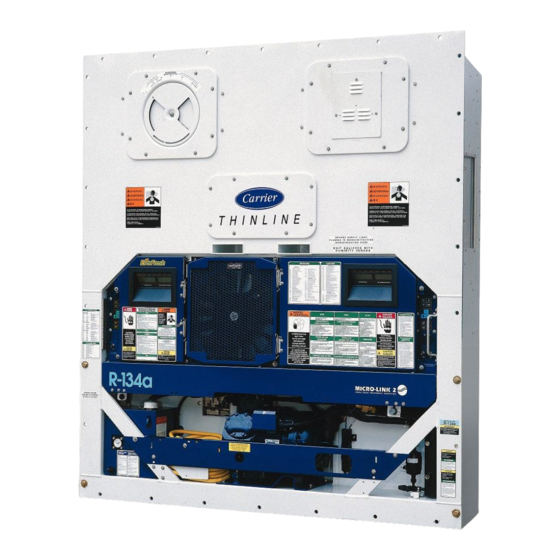
SECTION 2 DESCRIPTION 2.1 GENERAL DESCRIPTION evaporator coil heaters. The unit model number, serial number and parts identification number can be found on 2.1.1 Refrigeration Unit - - Front Section the serial plate to the left of the compressor. The unit is designed so that the majority of the 2.1.2 Fresh Air Makeup Vent components are accessible from the front, see Figure 2-1. -
Page 17: Evaporator Section
2.1.3 Evaporator Section The evaporator fans circulate air through the container by pulling it in the top of the unit, directing it through the The evaporator section (Figure 2-2) contains the evaporator coil, where it is heated or cooled, and temperature recorder bulb or return recorder sensor, discharging it at the bottom. -
Page 18: Compressor Section
2.1.4 Compressor Section discharge pressure regulator valve discharge/suction pressure transducers. The compressor section includes the compressor (with high pressure switch), power cable storage The supply temperature sensor, supply recorder sensor compartment, and autotransformer. and ambient sensor are located at the right side of the This section also contains the suction modulating valve, compressor. -
Page 19: Air Cooled Condenser Section
2.1.5 Air Cooled Condenser Section line valve and filter-drier. The air cooled condenser section (Figure 2-4) consists The condenser fan pulls air in the bottom of the coil and it of the condenser fan, condenser coil, receiver with sight is discharged horizontally out through the condenser fan glass/moisture indicator, quench valve, manual liquid grille. -
Page 20: Water-Cooled Condenser Section
2.1.6 Water-Cooled Condenser Section quench expansion valve, rupture disc, condenser pressure transducer, filter-drier, water couplings and The water-cooled condenser section (Figure 2-5) water pressure switch. The water cooled condenser consists of a water-cooled condenser, sight glass, replaces the standard unit receiver. 1. -
Page 21: Control Box Section
2.1.7 Control Box Section 2.1.8 Communications Interface Module The control box (Figure 2-6) includes the manual The communications interface module is a slave operation switches; circuit breaker (CB-1); compressor, module which allow communication with a master fan and heater contactors; control power transformer; central monitoring station. -
Page 22: Refrigeration System Data
2.2 REFRIGERATION SYSTEM DATA Number of Cylinders Model 06DR Weight (Dry) 118 kg (260 lb) a. Compressor/Motor Assembly Approved Oil Castrol Icematic SW--20 Oil Charge 3.6 liters (7.6 U.S. pints) The oil level range, with the compressor off, Oil Sight Glass should be between the bottom and one-eighth level of the sight glass. -
Page 23: Electrical Data
2.3 ELECTRICAL DATA CB-1 Trips at 29 amps CB-2 (50 amp) Trips at 62.5 amps a. Circuit Breaker CB-2 (70 amp) Trips at 87.5 amps b. Compressor 17.6 amps @ 460 vac Full Load Amps (FLA) Motor (with current limiting set at 21 amps) 380 vac, Single Phase, 460 vac, Single Phase, 50 hz... -
Page 24: Safety And Protective Devices
Orange wire Power Red wire Output Brown wire Ground Input voltage 5 vdc Output voltage 0 to 3.3 vdc i. Humidity Sensor Output voltage readings verses relative humidity (RH) percentage: 0.99 V 1.65 V 2.31 V 2.97 V j. Controller Setpoint Range --30 to +30 _C (--22 to +86 _F) 2.4 SAFETY AND PROTECTIVE DEVICES... -
Page 25: Refrigeration Circuit
2.5 REFRIGERATION CIRCUIT outlet. The valve maintains a constant superheat at the coil outlet regardless of load conditions. Starting at the compressor, (see Figure 2-7, upper During periods of low load, the suction modulating valve schematic) the suction gas is compressed to a higher decreases flow of refrigerant to the compressor. -
Page 26: Figure 2-7 Refrigeration Circuit Schematic
Circuit with Receiver 1.High Pressure Switch 2.Discharge Pressure Regulator Valve 3.Air-Cooled Condenser 4.Evaporator 5. Thermostatic Expansion Valve 6. External Equalizer Line 7. Hermetic Thermostatic Expansion Valve Bulb 8.Heat Exchanger 9. Rupture Disc 10. Moisture-Liquid Indicator 11. Condenser Pressure Transducer (CPT) 12. -
Page 27: Microprocessor
SECTION 3 MICROPROCESSOR 3.1 TEMPERATURE CONTROL MICROPRO- and cargo temperature parameters for future retrieval. CESSOR SYSTEM Coverage of the temperature control software begins with paragraph 3.2. Coverage of the DataCORDER The temperature control Micro-Link 3 microprocessor software is provided in paragraph 3.6. system (see Figure 3- 1) consists of a key pad, display module, control module (controller) and interconnecting wiring. -
Page 28: Figure 3- 3 Display Module
3.1.1 Key Pad Table 3-1 Key Pad Function The key pad (Figure 3- 2) is mounted on the right-hand FUNCTION side of the control box. The key pad consists of eleven Code Select Accesses function codes. push button switches that act as the user’s interface with the controller. -
Page 29: Controller
Mounting Screw Fuses Micro-Link 3 Control Circuit Power Connection Controller (Location: In back of controller) Connectors Software Programming Port Test Points Battery Pack Figure 3- 4 Micro-Link 3 Controller 3.1.3 Controller clear build up of frost and ice from the coil to ensure continuous conditioned air delivery to the load. -
Page 30: Modes Of Operation
To access the function codes, perform the following: below the frozen setpoint and then adjust to 24 hours thereafter. a. Press the CODE SELECT key, then press an arrow All defrost interval times reflect the number of key until the left window displays the desired code compressor runtime hours since the last defrost de--ice number. -
Page 31: Perishable Mode -- Conventional
3.3.8 Perishable Mode - - Conventional 1. The humidity sensor reading is above the set point. 2. The Supply air temperature is less than 0.25_C The unit is capable of maintaining supply air above set point. temperature to within ¦0.25_C (¦0.5_F) of set point. Supply air temperature is controlled by positioning of the 3. -
Page 32: Temperature Control -- Frozen Mode
In addition, if bulb mode is active, function code Cd37 compressor will restart. Under a condition of rapidly may be set to override the previous defrost termination changing return air temperature, the time delay may thermostat settings. (Refer to paragraph 4.10.4) The allow the return air temperature to rise slightly above set temperature at which the defrost termination thermostat point temperature before the compressor can restart. -
Page 33: Unit Pre-Trip Diagnostics
The unit is also fitted with interrogation connections (see 3 If a longer time is desired, press the ENTER key to Figure 3- 1) which may be used with the Carrier extend the time to 30 seconds. T-317... -
Page 34: Sensor Configuration (Dcf02)
(dCF02=64) 1 humidity input configuration to generic and selecting which data points 1 cargo probe (thermistor input) to record may be done using the Carrier Transicold Data 2 thermistor inputs(supply & return) Retrieval Program. 3 USDA thermistor inputs 1. Control mode... -
Page 35: Figure 3- 5 Standard Configuration Report
Raw Data Report for ABC1234567 May 31, 2001 to Jun 04, 2001 System Configuration at the Time of Interrogation: Interrogated On Sept 05, 2001 Extracted by DataLine Rev 1.0.0 Controller Software: 5120 Controller Serial #: 04163552 Bill of Lading #: 1 Origin: Origin Date: Destination:... -
Page 36: Logging Interval (Dcf03)
This function is designed to assist users who keep their DataCORDER configured for USDA The Carrier Transicold Data Reader (see Figure 3- 6) is recording, but do not install the probes for every trip. If all a simple to operate hand held device designed to extract the probes are disconnected, no alarms are activated. -
Page 37: Usda Cold Treatment
Files downloaded to the DataBANK card will be in cold treatment probe calibration and file management. Carrier ’dcx’ format. File name will be of the form: Refer to Data Retrieval manual 62-10629 for a more XXXXNNNNNNN_YYMMDDHHMM.dcx,... -
Page 38: Usda Cold Treatment Procedure
a. USDA Recording e. To initiate USDA Recording, connect the personal computer and perform the configuration as follows: A special type of recording is used for USDA cold treatment purposes. Cold treatment recording requires 1. Fill in ISO header information three remote temperature probes be placed at 2. -
Page 39: Table 3-4 Controller Configuration Variables
Table 3-4 Controller Configuration Variables CONFIGURATION TITLE DEFAULT OPTION NUMBER CnF01 Bypass Valve Enable CnF02 Evaporator Fan Speed dS (Dual) SS (Single) CnF03 Control Sensors FOUr duAL CnF04 Dehumidification Mode CnF05 Reserved for future use ---------- CnF06 Condenser Fan Speed Select OFF (Single) On (Variable) CnF07... -
Page 40: Table 3-5 Controller Function Codes
Table 3-5 Controller Function Codes (Sheet 1 of 4) Code TITLE DESCRIPTION Note: If the function is not applicable, the display will read “-- -- -- -- -- ” Display Only Functions Displays the SMV percent open. The right display reads 100% when the valve is Suction Modulation fully open and 0% when the valve is fully closed. - Page 41 Table 3-5 Controller Function Codes (Sheet 2 of 4) Cd22 Compressor Speed The status of the compressor is displayed (high, low or off). Cd23 Evaporator Fan Displays the current evaporator fan state (high, low or off). Controlled Cd24 Not used in this application Atmosphere State Compressor Run This code displays the time remaining until the unit goes into defrost (in tenths of...
- Page 42 Table 3-5 Controller Function Codes (Sheet 3 of 4) The stagger start offset time is the amount of time that the unit will delay at start- Stagger Start Offset up, thus allowing multiple units to stagger their control initiation when all units are Cd31 Time (Seconds) powered up together.
- Page 43 Table 3-5 Controller Function Codes (Sheet 4 of 4) Code Cd38 will display the current secondary supply temperature sensor reading Secondary Supply for units configured for four probes. If the unit is configured with a DataCORDER, Cd38 Cd38 will display “-- -- -- -- -- .” If the DataCORDER suffers a failure, (AL55) Cd38 Temperature Sensor will display the supply recorder sensor reading.
-
Page 44: Table 3-6 Controller Alarm Indications
Table 3-6 Controller Alarm Indications (Sheet 1 of 3) Code TITLE DESCRIPTION Alarm 11 is applicable to units with Single Evaporator Fan Capability (CnF32 set Evaporator Motor 1 AL11 to 1EFO) only. The alarm is triggered if the evaporator fan motor #1 internal pro- IP Trip tector opens. - Page 45 Table 3-6 Controller Alarm Indications (Sheet 2 of 3) Alarm 54 is activated by an invalid primary supply temperature sensor reading that is sensed outside the range of --50 to +70_C (--58_F to +158_F) or if the probe check logic has determined there is a fault with this sensor. If Alarm 54 is activated and the primary supply is the control sensor, the secondary supply sen- Primary Supply Tem- sor will be used for control if the unit is so equipped.
- Page 46 Table 3-6 Controller Alarm Indications (Sheet 3 of 3) Alarm 66 is triggered by a suction pressure transducer reading outside the valid Suction Pressure AL66 range of 73.20 cm Hg (30 in Hg) to 32.34 Kg/cm (460 psig). This is a display Transducer Failure alarm and has no associated failure action.
-
Page 47: Table 3-7 Controller Pre-Trip Test Codes
Table 3-7 Controller Pre-Trip Test Codes (Sheet 1 of 4) Code TITLE DESCRIPTION NOTE “Auto” or “Auto1” menu includes the: P, P1, P2, P3, P4, P5, P6 and rSLts. “Auto2” menu in- cludes P, P1, P2, P3, P4, P5, P6, P7, P8, P9, P10 and rSLts.“Auto3 menu includes P, P1, P2, P3, P4, P5, P6, P7, P8 and rSLts All lights and display segments will be energized for five seconds at the start of Pre-Trip Initiated... -
Page 48: Table 3-7 Controller Pre-Trip Test Codes
Table 3-7 Controller Pre-Trip Test Codes (Sheet 2 of 4) Requirements: For units equipped with secondary supply probe only. Pass/Fail Criteria: The temperature difference between primary and secondary probe (supply) is compared. P5-1 Supply Probe Test NOTE If this test fails, “P5-1” and FAIL will be displayed. If both Probe tests (this and the SUPPLY/ RETURN TEST) pass, because of the multiple tests, the display will read ’P 5’... - Page 49 Table 3-7 Controller Pre-Trip Test Codes (Sheet 3 of 4) Note, this test is skipped if the unit does NOT have: A compressor discharge sensor (CPDS). A discharge pressure transducer (DPT). Condenser pressure transducer (CPT). In addition, this test is skipped if: The sensed ambient temperature is less than 7_C (45_F).
- Page 50 Table 3-7 Controller Pre-Trip Test Codes (Sheet 4 of 4) Requirements: Test P8-1 must pass for this test to execute. Setup: The left display will read “P8-2,” and the right display will show the supply air temperature. A 60 minute timer is started. The unit will be required to main- tain the 0°C temperature to within + or -- 0.5_C (0.9_F) of set point until a Data- CORDER recording is executed.
-
Page 51: Table 3-8 Datacorder Function Code Assignments
Table 3-8 DataCORDER Function Code Assignments NOTE Inapplicable Functions Display “-- -- -- -- -- ” To Access: Press ALT. MODE key Code TITLE DESCRIPTION Recorder Supply Current reading of the supply recorder sensor. Temperature Recorder Return Current reading of the return recorder sensor. Temperature USDA 1,2,3 Temper- dC3-5... -
Page 52: Table 3-9 Datacorder Pre-Trip Result Records
Table 3-9 DataCORDER Pre-Trip Result Records Test TITLE DATA Heater On Pass/Fail/Skip Result, Change in current for Phase A, B and C Heater Off Pass/Fail/Skip Result, Change in currents for Phase A, B and C Pass/Fail/Skip Result, Water pressure switch (WPS) -- Open/Closed, Condenser Fan On Change in currents for Phase A, B and C Condenser Fan Off... -
Page 53: Table 3-10 Datacorder Alarm Indications
Table 3-10 DataCORDER Alarm Indications To Access: Press ALT. MODE key Code No. TITLE DESCRIPTION The supply recorder sensor reading is outside of the range of --50_C to 70_C (--58_F to +158_F) or, the probe check logic has determined there is a fault with this sensor. -
Page 54: Operation
SECTION 4 OPERATION 4.1 INSPECTION (Before Starting) power source. Place circuit breaker (CB-1) in position “I” (ON). Close and secure control box door WARNING 4.2.2 Connection to190/230 vac Power An autotransformer (Figure 4-1) is required to allow Beware of unannounced starting of the operation on nominal 230 volt power. -
Page 55: Upper Fresh Air Makeup Vent
4.3.1 Upper Fresh Air Makeup Vent with 15 mm (0.6 inch) H O external static above free blow. Two slots and a stop are designed into the disc for air flow adjustments. The first slot allows for a 0 to 30% air d. - Page 56 cooled condenser. The refrigeration unit will shift to air-cooled condenser operation when the water pres- sure switch closes. T-317...
-
Page 57: Water-Cooled Condenser With Condenser Fan Switch
4.4.2 Water-Cooled Condenser with Condenser 4.7.2 Check Controller Function Codes Fan Switch Check and, if required, reset controller Function Codes a. Connect the water supply line to the inlet side of con- (Cd27 through Cd39) in accordance with desired denser and the discharge line to the outlet side of the operating parameters. -
Page 58: Observe Unit Operation
on the right display, with the corresponding test num- PRE-TRIP SELECTION MENU ber to the left. The user may then press the DOWN Auto or Auto 1 Auto 2 Auto 3 ARROW to repeat the test, the UP ARROW to skip to the next test or the PRE--TRIP key to terminate test- P, P1, P2, P3, P, P1, P2, P3,... -
Page 59: Probe Check
4.9.2 Probe Check In this configuration, a probe check will not be run as a part of a normal defrost, but only as a part of a defrost If the DataCORDER is off, or in alarm mode the initiated due to a diagnostic reading outside of the limits. controller will revert to a four probe configuration which c.The 30 minute timer will be reset at each of the follow- includes the DataCORDER supply and return air probes... -
Page 60: Sequence Of Operation -- Perishable Mode Cooling
FALLING RISING TEMPERATURE TEMPERATURE +1.5 C (2.7 C (1.8 COOLING COOLING +0.5 C (0.9 +.20 SET POINT - -0.20 - - 0.5 C (0.9 - - 1 C (1.8 CIRCULATION CIRCULATION ONLY ONLY - - 1.5 C (2.7 Figure 4-4 Controller Operation - - Frozen Mode NOTE ENERGIZED DE- -ENERGIZED... -
Page 61: Sequence Of Operation
4.10.2 Sequence Of Operation - - fan motors (ES) energized and the COOL light illumi- Perishable Mode Heating nated. (See Figure 4-7.) b.When the air temperature decreases to a predeter- NOTE mined tolerance above set point, the in-range light is illuminated. -
Page 62: Figure 4-8 Defrost
4. The controller probe diagnostic logic determines that When a request for defrost is made by probe check, the a probe check is necessary based on the tempera- unit will enter defrost when the Defrost Temperature ture values currently reported by the supply and re- Sensor reading is at or below 25.6°C(78°F). -
Page 63: Troubleshooting
SECTION 5 TROUBLESHOOTING REMEDY/ REFERENCE CONDITION POSSIBLE CAUSE SECTION 5.1 UNIT WILL NOT START OR STARTS THEN STOPS External power source OFF Turn on Start-Stop switch OFF or defective Check No power to unit Circuit breaker tripped or OFF Check Autotransformer not connected 4.2.2 Circuit breaker OFF or defective... -
Page 64: Unit Runs But Has Insufficient Cooling
REMEDY/ REFERENCE CONDITION POSSIBLE CAUSE SECTION 5.3 UNIT RUNS BUT HAS INSUFFICIENT COOLING Compressor Compressor valves defective Abnormal pressures Controller malfunction Evaporator fan or motor defective 6.16 Refrigeration System Suction modulation valve malfunction 6.18 Condenser Pressure Transducer defective Check Shortage of refrigerant 6.7.1 5.4 UNIT WILL NOT HEAT OR HAS INSUFFICIENT HEATING Start-Stop switch OFF or defective... -
Page 65: Abnormal Pressures (Cooling)
REMEDY/ REFERENCE CONDITION POSSIBLE CAUSE SECTION 5.6 UNIT WILL NOT DEFROST PROPERLY - -Continued Frequent defrost Wet load Normal 5.7 ABNORMAL PRESSURES (COOLING) Condenser coil dirty 6.10 Condenser fan rotating backwards 6.11 Condenser fan inoperative 6.11 Refrigerant overcharge or noncondensibles 6.7.1 High discharge pressure Discharge pressure regulator valve defective... -
Page 66: No Evaporator Air Flow Or Restricted Air Flow
REMEDY/ REFERENCE CONDITION POSSIBLE CAUSE SECTION 5.10 NO EVAPORATOR AIR FLOW OR RESTRICTED AIR FLOW Frost on coil Evaporator coil blocked Dirty coil 6.15 Evaporator fan motor internal protector open 6.16 Evaporator fan motor(s) defective 6.16 No or partial evaporator air flow Evaporator fan(s) loose or defective 6.16 Evaporator fan contactor defective... -
Page 67: Figure 6-1. Piercing Valve
SECTION 6 SERVICE NOTE 4. Install the u-shaped block and nut onto the base of To avoid damage to the earth’s ozone layer, use the piercing valve that was removed in step 2. a refrigerant recovery system whenever remov- 5. Tighten the valve to the process tube by turning the ing refrigerant. -
Page 68: Figure 6-2. Manifold Gauge Set
6.4 REFRIGERANT RECOVERY Only a R-134a manifold gauge set with self-sealing hoses, as shown in Figure 6-3 (CTD P/N 07-00294-00, 1. Disconnect the tube clamp connected to the baffle which includes items 1 through 6) can be used when plate on the liquid line process tube. Remove the working on the models covered within this manual. -
Page 69: Refrigerant Leak Checking
(The pump is available from Carrier Trans- procedures are completed. icold, P/N 07-00176-11.) c. If possible, keep the ambient temperature above 15. Using the tubing cutter, cut-off the excess tubing as 15.6_C (60_F) to speed evaporation of moisture. -
Page 70: Refrigerant Charge
b. The recommended method to evacuate and dehy- d. On units equipped with a receiver, the level should be drate the system is to connect three evacuation between the glasses. On units equipped with a water hoses (see Figure 6-4) to the vacuum pump and cooled condenser, the level should be at the center of refrigeration unit. -
Page 71: Figure 6-4. Vacuum Pump Connections
normal operating system pressures, then the CAUTION charge should be correct. If the discharge pressure is more than ten psig below the curve, add three pounds of R-134a Make sure supply air temperature does not refrigerant through the suction line process tube. go below the original set point for more than five minutes, or damage to the load g. -
Page 72: Figure 6-5 Compressor
6.8 COMPRESSOR WARNING Make sure power to the unit is OFF and power plug disconnected before replacing the compressor. NOTES The compressor should not operate in a vacuum greater than 500 mm/hg (20 inches/hg). The service replacement compressor is 1. Discharge Flange 8. -
Page 73: Figure 6-6 Exploded View Of Valve Plate
6.8.2 Compressor Disassembly WARNING Before disassembly of any external com- pressor component make sure to relieve possible internal pressure by loosening the bolts and tapping the component with a soft hammer to break the seal. 1. Oil Pressure Relief 3. Oil Suction Tube Valve 4. -
Page 74: Figure 6-8 Oil Pump And Bearing Head
h. Be very careful not to damage the motor windings Set screw must be removed. when removing motor end cover (see Figure 6-10), as the cover fits over the winding coils. Loosen the cap screws, break the seal and then re- move all capscrews except one in the top of the cover. -
Page 75: Figure 6-11 Equalizing Tube And Lock Screw Assembly
1. Equalizer Tube and 3. Counterweight -- Lock Screw Assembly Motor End 1. Suction Valve 3. Valve Plate Dowel 2. Lockwasher 2. Suction Valve Positioning Spring Figure 6-11 Equalizing Tube and Lock Screw Assembly Figure 6-13 Suction Valve & Positioning Springs Suction valves are positioned by dowel pins (see Figure Figure 6-13). -
Page 76: Compressor Oil Level
The correct oil charge is 3.6 liters (7.6 U.S. pints). CAUTION Service replacement compressors are shipped Use only Carrier Transicold approved without oil. Polyol Ester Oil (POE) - - Castrol-Icematic SW20 compressor oil with R-134a. Buy in When first adding oil to the compressor, add quantities of one quart or smaller. -
Page 77: Figure 6-15 High Pressure Switch Testing
d. Removing Oil from the Compressor 1. Cylinder Valve 1. If the oil level recorded in step a.3 is above one-eighth and Gauge level of the capacity of the sight glass, oil must be removed from the compressor. 2. Pressure Regulator 3. -
Page 78: Water Cooled Condenser Cleaning
coil, and discharges horizontally through the front of the cap on water-cooled condenser inlet tube (replaces unit. To replace motor assembly: tubing flare nut). De-scale tubing if necessary. a. Open condenser fan screen guard. What You Will Need: b. Loosen two square head set screws on fan. (Thread 1. -
Page 79: Figure 6-17 Water Cooled Condenser Cleaning - Gravity Circulation
9 Following the water flush, circulate a 56.7 gram (2 WARNING ounce) per 3.785 liter (1 U.S. gallon) solution of Oakite No. 22 thru the tubes to neutralize. Drain this solution. Oakite No. 32 is an acid. Be sure that the 10 Flush the tubes thoroughly with fresh water. -
Page 80: Figure 6-18 Thermostatic Expansion Valve Bulb
1. Pump down the unit and replace filter-drier. 6.14.1 Checking Superheat. 2. Evacuate the system in accordance with paragraph 6.6. 3. After unit is in operation, inspect for moisture in sys- NOTE tem and check charge. Proper superheat measurement should be completed at --18_C (0_F) container box tem- 6.14 THERMOSTATIC EXPANSION VALVE perature where possible. -
Page 81: Hermetic Valve Replacement
6.14.2 Hermetic Valve Replacement CAUTION a. Removing the Expansion Valve NOTES If the thermostatic expansion valve is found to be in need of replacement, then the 1. The TXV is a hermetic valve and does not power head and cage assembly are to have adjustable superheat. -
Page 82: Figure 6-20. Evaporator Fan Assembly
c. Determine which heater(s) need replacing by check- ing resistance on each heater. Refer to paragraph 2.3 for heater resistance values d. Remove hold-down clamp securing heaters to coil. e. Lift the bent end of the heater (with the opposite end down and away from coil). -
Page 83: Figure 6-21 Suction Modulation Valve (Smv)
in high speed. In the economy perishable mode they 6.18 SUCTION MODULATION VALVE should switch speeds and in the frozen mode, the mo- On start up of the unit, the valve will reset to a known tors should run in low speed. open position. -
Page 84: Checking The Stepper Valve
Checking with SMA-12 portable stepper drive tester i. If no voltage is present in any step, the output from the controller may be faulty The SMA-12 portable stepper drive tester (Carrier Transicold P/N 07-00375-00) is a battery operated 6.19 AUTOTRANSFORMER stepper drive which will open and close the SMV, which allows a more thorough check of the motor. - Page 85 d. Using a voltmeter, and with the primary supply circuit WARNING ON, check the primary (input) voltage (460 vac). Next, check the secondary (output) voltage (230 vac). The transformer is defective if output voltage is not available. With power OFF discharge the capacitor and disconnect the circuit wiring.
-
Page 86: Figure 6-22 Controller Section Of The Control Box
This test point enables the user to check if the heat Figure 6-22 Controller Section of the Control Box termination thermostat (HTT) contact is open or closed. a. Obtain a grounding wrist strap (Carrier Transicold 6.21.3 Controller Programming Procedure part number 07--00--304--00)and a static dissipation To load new software into the module, the programming mat (Carrier Transicold part number 07--00304--00. -
Page 87: Removing And Installing The Controller
7. The Display module will go blank briefly, then read Torque values for mounting screws (item 2, see “Pro donE” when the software loading has loaded. (If Figure 6-22) are 0.23 mkg (20 inch-pounds). Torque a problem occurs while loading the software: the Dis- value for the connectors is 0.12 mkg (10 inch-pounds). -
Page 88: Figure 6-23 Sensor Types
Table 6-1 Sensor Temperature/Resistance Chart d. Prepare the cables by cutting wires to the opposite of the sensor. (See Figure 6-24.) Temperature Temperature Resistance When installing a single wire color two wire sensor, Centigrade Fahrenheit (Ohms) cut one wire of existing two wire cable 40 mm (1-1/2 inch) shorter than the other wire. -
Page 89: Figure 6-24 Sensor And Cable Splice
REPLACEMENT 2 WIRE TO 2 WIRE OR 3 WIRE TO 3 WIRE BLACK RED/WHITE REPLACEMENT FOR DUAL SINGLE Cable SENSOR CONFIGURATION Large Heat Shrink Heat Shrink Sensor (Typical) Tubing Tubing Figure 6-24 Sensor and Cable Splice 6.23.3 Sensor Re- -Installation Evaporator Grille a. -
Page 90: Figure 6-27. Electronic Partlow Temperature Recorder
Recorder Door Change Chart Button Recorder Box Pen Tip Stylus Arm Connector Calibration Button (Located underneath) Mounting Screws, #10-24 x 7/16 inches long Hold Down Tab Chart Retaining Nut Figure 6-27. Electronic Partlow Temperature Recorder If the power has been OFF for more than thirty days, the NOTE recorder will NOT re--synchronize (the chart will not Failure to press the change chart button, when... -
Page 91: Maintenance Of Painted Surfaces
An adhesive sealant must be used to c. Press the calibration button and the pen will position make the repair watertight. The adhesive sealant itself to the correct temperature reading. (Sikaflex 221) is included in Crack Repair Kit Carrier T--317 6-25... -
Page 92: Figure 6-28 Door Hinge Repair
The inserts and epoxy are contained in repair kit, Carrier Transicold part number 76-50084-00 (see Table 6-3). There are 6 different inserts used in the control box. -
Page 93: Table 6-2 Crack, Chip & Hole Repair Kit
Static Mixing Tube (Loctite 983440) 07--00390--00 . . . Instruction Sheet 98--02338--00 Note: Insert repair procedures require use of an Application Gun, Carrier part number 07--00391--00 (Loctite 983435) Table 6-4 Drill Information Item Insert part number Drill size and depth 34- 06231- 01 10.3 mm x 17.8 mm deep (.404 in. -
Page 94: Figure 6-29. Insert Location
Figure 6-29. Insert Location T--317 6-28... -
Page 95: Figure 6-30. Communications Interface Installation
6.27 COMMUNICATIONS INTERFACE MODULE c.. Remove the circuit breaker panel, with circuit INSTALLATION breaker, from the control box. d.. Locate, wires CB21/CIA3, CB22/CIA5 CB23/CIA7 that have been tied back in the wire harness. Remove the protective heat shrink from the ends of the wires. e.. -
Page 96: Table 6-6 Wear Limits For Compressors
Table 6-6 Wear Limits For Compressors MAXIMUM WEAR FACTORY MAXIMUM FACTORY MINIMUM BEFORE REPAIR PART NAME inches inches inches MAIN BEARING Main Bearing Diameter 1.6268 41.3207 .0020 0.0508 Main Bearing Journal Diameter 1.6233 41.2318 .0020 0.0508 PUMP END Main Bearing Diameter 1.3760 34.9504 .0020... -
Page 97: Table 6-8 Compressor Torque Values
Table 6-8 Compressor Torque Values TORQUE RANGE SIZE USAGE DIAMETER THREADS ft-lb (inches) PER INCH 1/16 27 (pipe) 8 -- 12 11 -- 16 Pipe Plug -- Crankshaft 20 (pipe) 6 -- 10 8 -- 13 Oil Return Check Valve -- Crankcase 20 (pipe) 20 -- 25 27 -- 34... -
Page 98: Table 6-9 R-134A Temperature - Pressure Chart
Table 6-9 R-134a Temperature - Pressure Chart Temperature Vacuum Temperature Pressure “/hg cm/hg kg/cm@ psig kg/cm@ --40 --40 14.6 49.4 37.08 0.49 24.5 168.9 1.72 1.69 26.1 180.0 1.84 1.80 12.3 41.6 31.25 0.42 27.8 191.7 1.95 1.92 --30 --34 32.8 24.64 0.33... -
Page 99: Figure 6-31 R-134A Compressor Pressure And Motor Current Curves Versus Ambient Temperature
Note: Curves to be used as troubleshooting guide only for model series 69NT40 with fresh air makeup vent closed, unit powered on 460 VAC/60hz and SMV 100% open. (Bar) psig (22.0) (20.7) (19.3) (17.9) 35_F (1.7_C) (16.6) (15.2) (13.8) (12.4) (11.0) (9.7) (8.3) -
Page 100: Figure 6-31 R-134A Compressor Pressure And Motor Current Curves Versus Ambient Temperature
(Bar) psig (.97) (.83) (.69) (.55) 35_F (1.7_C) Box (.41) (.28) (.14) 0_F (--17.8_C) Box - -2 (- -.14) (- -.28) - -4 (- -.41) - -6 (15.6) (21.1) (26.7) (32.2) (37.8) (43.3) (48.9) (_C) Ambient Air Temperature Compressor Suction Pressure Versus Ambient Air Temperature at Stable Box Temperature 35_F (1.7_C) Box 0_F (--17.8_C) Box (_C) -
Page 101: Electrical Wiring Schematic
SECTION 7 ELECTRICAL WIRING SCHEMATIC 7.1 INTRODUCTION This section contains the Electrical Schematics and Wiring Diagrams. The diagrams are presented as follows: Figure 7-1 Provides the legend for use with all figures. Figure 7-2 Provides the schematic diagram for units covered in this manual. Figure 7-3 Supplements the other schematic diagrams and provides schematics for the Upper and Lower VPS . -
Page 102: Figure 7-1 Legend
LEGEND SYMBOL DESCRIPTION (Schematic Location) SYMBOL DESCRIPTION (Schematic Location) AMBS AMBIENT SENSOR (E- -19) HUMIDITY SENSOR (G- -20) BYPASS MODULE (D- -20) HOSE HEATER SAFETY THERMOSTAT (G- -14) CIRCUIT BREAKER - - 460 VOLT (J- -1) HEAT TERMINATION THERMOSTAT (F- -12) CIRCUIT BREAKER - - AUTO TRANSFORMER (D- -1) HUMIDITY WATER HEATER (Figure 7-3) CRANKCASE HEATER (T- -2) -
Page 103: Figure 7-2 Schematic Diagram
Figure 7-2 SCHEMATIC DIAGRAM T-317... -
Page 104: Figure 7-3 Schematic Diagram -- Transfresh And Vent Position Sensors (Vps)
SEE FIGURE SEE FIGURE 7--2 7--2 TO KB7 TransFRESH CONTROLLER Upper Air Exchange VPS Lower Air Exchange VPS Figure 7-3 SCHEMATIC DIAGRAM - - TransFRESH and Vent Position Sensors (VPS) T--317... -
Page 105: Figure 7-4 Schematic Diagram, Wiring Diagram-- Electronic Partlow Recorder
NOTE: STANDARD CONTROLLER JUMPERS: MA3 TO MA7 AND MA9 TO MA11 (SEE Figure 7-2 ) ARE REMOVED IN THIS APPLICATION NOTE: STANDARD CONTROLLER JUMPERS: MA3 TO MA7 AND MA9 TO MA11 (SEE Figure 7-2) ARE REMOVED IN THIS APPLICATION Figure 7-4 SCHEMATIC DIAGRAM, WIRING DIAGRAM- - Electronic Partlow Recorder T-317... -
Page 106: Figure 7-5 Unit Wiring Diagram
UPPER VPS [DF11] TRC2 TRC1 WIRES TO TR X2: DF--(TFC), P--(TFC), CIB1, GRD, CHA2, RMA, KA12, EFA2, HRA2 & CR8 ECG1 LOWER VPS (ICF MAY BE IN CONTROL BOX) Figure 7-5 UNIT WIRING DIAGRAM - - (Sheet 1 of 2) T--317... - Page 107 [UVPS1] [UVPS2] [HPRB] NOTE: RM MAY BE OUTSIDE UVPS3 TFC1 CFA1 [RMC] NOTE: WHEN EB, ED, BM OR CFS IS/ARE INSTALLED, WIRE DESTINATIONS CHANGE FROM THE STANDARD. ADDRESSES FOR THE CHANGED DESTINATIONS ARE SHOWN IN BRACKETS “[XXX]”. Figure 7-5 UNIT WIRING DIAGRAM (Sheet 2 of 2) T-317...
- Page 108 INDEX Discharge Pressure Regulator Valve, 2-3 Display Module, 3-2 Air Cooled Condenser Section, 2-4 Alarm, 3-6, 3-10, 3-12, 3-18, 3-27 Ambient Sensor, 2-3 Evacuation, 6-3 Arctic Mode, 3-4 Evaporator, 6-15 Autotransformer, 6-18 Evaporator Fan, 3-4, 6-16 Evaporator Section, 2-2 Expansion Valve, 6-14 Bulb Mode, 3-5 Failure Action, 3-4 Capacitors, 6-16...
- Page 109 INDEX - - Continued Refrigerant Charge, 6-4 Refrigeration, Repair, 6-1 Key Pad, 3-2 Refrigeration Circuit, 2-10 Refrigeration System Data, 2-7 Refrigeration Unit -- Front Section, 2-1 Leak Checking, 6-3 Required Tools, 6-30 Liquid Line Process Tube, 2-5, 6-1, 6-6, 6-10 Rupture Disc, 2-5 Logging Interval, 3-10 Lower Air, 1-2...
- Page 110 INDEX - - Continued Water Cooled Condenser, 6-12 Valve Water Pressure Switch, 2-5 Discharge Pressure Regulator, 2-3 Water--Cooled Condenser, 2-5 Quench Expansion, 2-3 Water--Cooled Condenser Section, 2-5 Stepper Motor Suction Modulation, 2-3 Wear Limits, 6-30 Vent Postion Sensor, 6-21 Wiring Schematic, 7-1 Index-3 T-317...
- Page 112 Carrier Transicold Division, Carrier Corporation Container Products Group P.O. Box 4805 Syracuse, N.Y. 13221 U.S A www.carrier.transicold.com A member of the United Technologies Corporation family. Stock symbol UTX ©2004 Carrier Corporation D Printed in U. S. A. 11/04...