
Related Manuals for Carrier Streamline Scroll 69NT20-531-300


Summary of Contents for Carrier Streamline Scroll 69NT20-531-300
- Page 1 Transicold Container Refrigeration Model 69NT20-531-300 Streamline Scroll T-309 Rev A Operation & Service...
- Page 2 69NT20-531-300 Streamline Scroll Carrier Transicold. A member of the United Technologies Corporation family. Stock symbol UTX. Carrier Transicold Divsion, Carrier Corporation, P.O. Box 4805, Syracuse, N.Y. 13221 U. S. A. ã 2002 CarrierCorporation D Printed in U. S. A. 07/02...
-
Page 3: General Safety Notices
GENERAL SAFETY NOTICES The following general safety notices supplement the specific warnings and cautions appearing elsewhere in this manual. They are recommended precautions that must be understood and applied during operation and maintenance of the equipment covered herein. The general safety notices are presented in the following three sections labeled: First Aid, Operating Precautions and Maintenance Precautions. - Page 4 Make sure that the unit circuit breaker(s) (CB-1 & CB-2) and the START-STOP switch (ST) are in the “O” (OFF) position before connecting to any electrical power source. Never use air for leak testing. It has been determined that pressurized, mixtures of refrigerant and air can undergo combustion when exposed to an ignition source.
- Page 5 (frontseated). Internal damage will result from operating the compressor in a deep vacu- Use only Carrier Transicold approved Polyol Ester Oil (POE) - - Mobil ST32 compressor oil with R-134a. Buy in quantities of one quart or smaller. When using this hygroscopic oil, immediately reseal.
-
Page 6: Table Of Contents
PARAGRAPH NUMBER GENERAL SAFETY NOTICES FIRST AID ..............OPERATING PRECAUTIONS MAINTENANCE PRECAUTIONS UNIT LABEL IDENTIFICATION... - Page 7 2.5.1 Standard Operation 2.5.2 Economized Operation 2.5.3 Unloaded Operation ............MICROPROCESSOR .
- Page 8 OPERATION ................. INSPECTION (Before Starting) CONNECT POWER .
- Page 9 SERVICE ..................SECTION LAYOUT .
- Page 10 6.21.1 Handling Modules ............6.21.2 Controller Trouble-Shooting 6.21.3 Controller Programming Procedure 6.21.4 Removing and Installing a Module...
- Page 11 FIGURE NUMBER Figure 2-1 Refrigeration Unit - - Front Section Figure 2-2 Evaporator Section ............Figure 2-3 Compressor Section .
- Page 12 FIGURE NUMBER Figure 6-22 Return Sensor Positioning Figure 6-23 Door Hinge Repair ............Figure 6-24.
-
Page 13: Introduction
Carrier Transicold Container Unit Matrix manual, publication T- -300. Printed copies of the T- -300 may be obtained from Carrier Transicold. Also, a weekly updated copy may be found at the Carrier Web site, www.carrier.refrigeration.com. 1.3 OPTION DESCRIPTIONS Various options may be factory or field fitted to the base unit. -
Page 14: Cable Restraint
1.3.11 460 Volt Cable Various power cable and plug designs are available for the main 460 volt supply. The plug options tailor the cables to each customers requirements. 1.3.12 Cable Restraint Various designs are available for storage of the power cables. -
Page 15: Description
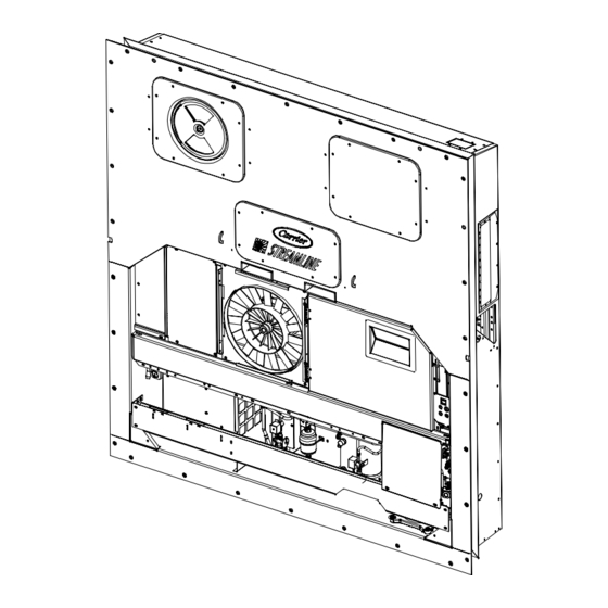
2.1 GENERAL DESCRIPTION 2.1.1 Refrigeration Unit - - Front Section The unit is designed so that the majority of the components are accessible from the front, see Figure 2-1. The upper access panels allow entry into the evaporator section, and the center access panel allows access to the evaporator expansion valve, unloader Access Panel (Evap. -
Page 16: Evaporator Section
2.1.3 Evaporator Section The evaporator section (Figure 2-2) contains the return recorder sensor, return temperature sensor, evaporator expansion valve, unloader valve, suction modulation valve, dual-speed evaporator fans (EM1 and EM2), evaporator coil and heater, defrost heaters, defrost temperature sensor, heat termination thermostat and suction temperature sensor. -
Page 17: Compressor Section
2.1.4 Compressor Section The compressor section includes the compressor (with high pressure switch) and the oil separator. This section also contains the oil return solenoid, compressor power plug, the discharge pressure Compressor Guard Supply Temperature/Supply Recorder Sensor Assembly Ambient Sensor Supply Air Thermometer Port (location) Oil Drain Compressor... -
Page 18: Air Cooled Condenser Section
2.1.5 Air Cooled Condenser Section The air cooled condenser section (Figure 2-4) consists of the condenser fan, condenser coil, receiver, sight glass/moisture indicator, liquid line service valve, filter-drier and fusible plug. Grille and Venturi Assembly Condenser Fan Condenser Fan Motor Condenser Coil Condenser Motor Mounting Bracket Condenser Coil Cover... -
Page 19: Control Box Section
2.1.6 Control Box Section The control box (Figure 2-5) includes the manual operation switches; circuit breaker (CB-1); compressor, fan and heater contactors; control power transformer; fuses; key pad; display module; current sensor module; controller module expansion module and the communications interface module. Compressor Phase A Contactor Compressor Phase B Contactor Heater Contactor... -
Page 20: Refrigeration System Data
2.2 REFRIGERATION SYSTEM DATA a Compressor/Motor a. Compressor/Motor Assembly b. Evaporator Expansion Valve Superheat c. Economizer Expansion Valve Superheat d Heater Termination Thermostat d. Heater Termination Thermostat e. High Pressure Switch e High Pressure Switch f. Refrigerant Charge g. Fusible Plug g Fusible Plug h. -
Page 21: Electrical Data
2.3 ELECTRICAL DATA CB-1 Trips at CB-2 (50 amp) Trips at a. Circuit Breaker a. Circuit Breaker CB-2 (70 amp) Trips at b. Compressor Full Load Amps (FLA) Motor Full Load Amps c. Condenser Fan c. Condenser Fan Motor Horsepower Rotations Per Minute Voltage and Frequency Bearing Lubrication... -
Page 22: Safety And Protective Devices
PARAGRAPH 2.3 - - Continued Orange wire Red wire Brown wire Input voltage Output voltage g Humidity Sensor g. Humidity Sensor Output voltage readings verses relative humidity (RH) percentage: 2.4 SAFETY AND PROTECTIVE DEVICES Unit components are protected from damage by safety and protective devices listed in the following table. -
Page 23: Refrigeration Circuit
2.5 REFRIGERATION CIRCUIT 2.5.1 Standard Operation Starting at the compressor, (see Figure 2-6, upper schematic) the suction gas is compressed to a higher pressure and temperature. In the standard mode, both the economizer and unloader solenoid valves are closed. The gas flows through the discharge service valve into the oil separator. -
Page 24: Figure 2-6 Refrigeration Circuit Schematic - - Standard Operation
STANDARD OPERATION WITH RECEIVER EVAPORATOR CONDENSER ECONOMIZER TXV BULB FILTER DRIER ECONOMIZER ECONOMIZER RECEIVER FUSIBLE PLUG LIQUID LINE SERVICE CONNECTION DISCHARGE STANDARD OPERATION WITH WATER COOLED CONDENSER EVAPORATOR CONDENSER ECONOMIZER TXV BULB FILTER DRIER ECONOMIZER ECONOMIZER SIGHTGLASS/ MOISTURE INDICATOR LIQUID LINE SERVICE CONNECTION Figure 2-6 Refrigeration Circuit Schematic - - Standard Operation... -
Page 25: Figure 2-7 Refrigeration Circuit Schematic - - Economized Operation
EVAPORATOR CONDENSER ECONOMIZER TXV BULB ECONOMIZER ECONOMIZER RECEIVER LIQUID LINE SERVICE CONNECTION LIQUID Figure 2-7 Refrigeration Circuit Schematic - - Economized Operation ECONOMIZER TXV BULB RECEIVER LIQUID Figure 2-8 Refrigeration Circuit Schematic - - Unloaded Operation LOW SIDE ACCESS VALVE TXV BULB OIL SEPARATOR ECONOMIZER PRESSURE... -
Page 26: Microprocessor
3.1 TEMPERATURE CONTROL MICROPRO- CESSOR SYSTEM The temperature control Micro-Link 2i microprocessor system (see Figure 3- 1) consists of a key pad, display module, the control module & expansion module set (controller) and interconnecting wiring. The controller houses the temperature control software and the DataCORDER Software. -
Page 27: Display Module
3.1.1 Key Pad The key pad (Figure 3- 2) is mounted on the right-hand side of the control box. The key pad consists of eleven push button switches that act as the user’s interface with the controller. Descriptions of the switch functions are provided in Table 3-1. -
Page 28: Controller
Mounting Screw Micro-Link 2i Control/DataCORDER Module Connectors Test Points Fuses Figure 3- 4 Control and Expansion Modules 3.1.3 Controller CAUTION Do not remove wire harnesses from control- ler modules unless you are grounded to the unit frame with a static safe wrist strap. CAUTION Unplug all controller module wire harness connectors before performing arc welding... -
Page 29: Operational Software (Function Codes)
3.2.2 Operational Software (Function codes) The Operational Software is the actual operation programming of the controller which activates or deactivates components in accordance with current unit operating conditions and operator selected modes of operation. The programming is divided into function Codes. Some of the codes are read only while the remaining codes may be user configured. -
Page 30: Perishable Mode - - Economy
mode and the heaters will be energized . The unit will transition back to the perishable idle mode when the temperature rises to 0.2_C (0.4_F) below the set point and the heaters will de-energize 3.3.7 Perishable Mode - - Economy The economy mode is an extension of the conventional mode. -
Page 31: Temperature Control - - Frozen Mode
1. Bulb mode code Cd35 is set to “Nor.” 2. Dehumidification code Cd33 is set to “Off.” 3. The user changes the set point to one that is in the frozen range. When bulb mode is disabled by any of the above, the evaporator fan operation for dehumidification reverts to “alt”... -
Page 32: Unit Pre-Trip Diagnostics
The unit is also fitted with interrogation connections (see Figure 3- 1) which may be used with the Carrier Transicold Data Reader to down load data. A personal computer with Carrier Transicold Data View software may also be used to download data and configure settings. -
Page 33: Sensor Configuration (Dcf02)
A list of the data points available for recording follows. Changing the configuration to generic and selecting which data points to record may be done using the Carrier Transicold Data Retrieval Program. 1. Control mode 2. Control temperature 3. Frequency 4. -
Page 34: Figure 3- 5 Standard Configuration Download Report
Raw Data Report for ABC1234567 May 31, 2001 to Jun 04, 2001 System Configuration at the Time of Interrogation: Interrogated On Sept 05, 2001 Extracted by DataLine Rev 1.0.0 Controller Software: 5120 Controller Serial #: 04163552 Bill of Lading #: 1 Origin: Origin Date: Destination:... -
Page 35: Logging Interval (Dcf03)
DataReader, DataLine/DataView or a communications interface module. a. DataReader The Carrier Transicold Data Reader (see Figure 3- 6) is a simple to operate hand held device designed to extract data from the DataCORDER and then upload it to a personal computer. The Data Reader has the ability to store multiple data files. -
Page 36: Usda Cold Treatment
Refer to Data Retrieval manual 62-10629 for a more detailed explanation of the DataLINE interrogation software. The DataLine manual may be found on the net at www.contaner.carrier.com 3.6.11 USDA Cold Treatment Sustained cold temperature has been employed as an effective postharvest method for the control of Mediterranean and certain other tropical fruit flies. -
Page 37: Datacorder Alarms
Place in pulp of the product located next Sensor 1 to the return air intake. Place in pulp of the product five feet from the end of the load for 40 foot con- tainers, or three feet from the end of the Sensor 2 load for 20 foot containers. -
Page 38: Table 3-4 Controller Configuration Variables
Table 3-4 Controller Configuration Variables 1. Configuration numbers not listed are not used in this application. These items may appear when loading configuration software to the controller but changes will not be recognized by the controller programming. CONFIGURATION NUMBER CnF02 Evaporator Fan Speed CnF04 Dehumidification Mode... - Page 39 Table 3-5 Controller Function Codes (Sheet 1 of 3) Code TITLE Note: If the function is not applicable, the display will read “-- -- -- -- -- ” Displays the SMV percent open. The right display reads 100% when the valve is Cd01 Suction Modulation fully open.
-
Page 40: Table 3-5 Controller Function Codes
Table 3-5 Controller Function Codes (Sheet 2 of 3)ff Cd22 Compressor State The status of the compressor is displayed (Off, On). Cd23 Evaporator Fan Displays the current evaporator fan state (high, low or off). Cd24 Controlled Not used in this application Atmosphere State Compressor Run This code displays the time remaining until the unit goes into defrost (in tenths of... - Page 41 Table 3-5 Controller Function Codes (Sheet 3 of 3) The stagger start offset time is the amount of time that the unit will delay at start- Cd31 Stagger Start Offset up, thus allowing multiple units to stagger their control initiation when all units Time (Seconds) are powered up together.
-
Page 42: Table 3-6 Controller Alarm Indications
Table 3-6 Controller Alarm Indications (Sheet 1 of 4) Code TITLE Alarm 13 is triggered if the control module has lost communication with the ex- pansion module for more than five minutes or communication fails within the first 15 seconds on power up. This alarm triggers failure action C (evaporator fan AL13 Expansion Module only) or D (all machinery off) of Function Code Cd29 if the unit has a perishable set point. - Page 43 Table 3-6 Controller Alarm Indications (Sheet 2 of 4) Alarm 25 is triggered by the opening of the condenser motor internal protector and will disable all control units except for the evaporator fans. This alarm will remain active until the motor protector resets. This alarm triggers failure action AL25 Condenser Fan Mo- tor Safety C (evaporator fan only) or D (all machinery off) of Function Code Cd29 if the...
- Page 44 Table 3-6 Controller Alarm Indications (Sheet 3 of 4) Alarm 56 is activated by an invalid primary return temperature sensor reading that is outside the range of - -50 to +70_C (- -58_F to +158_F). If Alarm 56 is acti- vated and the primary return is the control sensor, the secondary return sensor will be used for control if the unit is so equipped.
- Page 45 Table 3-6 Controller Alarm Indications (Sheet 4 of 4) If the Controller is configured for four probes without a DataCORDER, the DataCORDER alarms AL70 and AL71 will be processed as Controller alarms AL70 and AL71. Refer to Table 3-10. The Controller performs self-check routines. if an internal failure occurs, an “ERR”...
-
Page 46: Table 3-7 Controller Pre-Trip Test Codes
Table 3-7 Controller Pre-Trip Test Codes (Sheet 1 of 4) Code TITLE “Auto” or “Auto1” menu includes the: P0, P1, P2, P3, P4, P5, P6 and rSLts. “Auto2” menu includes P0, P1, P2, P3, P4, P5, P6, P7, P8, P9, P10 and rSLts. All lights and display segments will be energized for five seconds at the start of the pre-trip. - Page 47 Table 3-7 Controller Pre-Trip Test Codes (Sheet 2 of 4) Requirements: For units equipped with secondary supply probe only. Pass/Fail Criteria: The temperature difference between primary and secondary probe (supply) is compared. P5-1 Supply Probe Test Requirements: For units equipped with secondary return probe only. Pass/Fail Criteria: The temperature difference between primary and secondary probe (return) is compared.
- Page 48 Table 3-7 Temperature Controller Pre-Trip Test Codes (Sheet 3 of 4) P7-0 through P10 are included with the “Auto2” only. P7-0 High Pressure S it h Cl Switch Closed Setup: With the unit running, the condenser fan is de-energized, and a 15 minute timer is started.
- Page 49 Table 3-7 Controller Pre-Trip Test Codes (Sheet 4 of 4) Setup: If the container temperature is below 7.2_C (45_F), the set point is changed to 7.2_C and a 180 minute timer is started. The control will then be placed in the equivalent of normal heating. If the container temperature is above 7.2_C at the start of the test, then the test proceeds immediately to test 10- -1.
-
Page 50: Table 3-8 Datacorder Function Code Assignments
Table 3-8 DataCORDER Function Code Assignments Inapplicable Functions Display “ -- -- -- -- -- ” Code TITLE Recorder Supply Current reading of the supply recorder sensor. Temperature Recorder Return Current reading of the return recorder sensor. Temperature USDA 1,2,3 Tem- dC3-5 Current readings of the three USDA probes. -
Page 51: Table 3-9 Datacorder Pre-Trip Result Records
Table 3-9 DataCORDER Pre-Trip Result Records Test TITLE Heater On Heater Off Condenser Fan On Condenser Fan Off Low Speed Evaporator Fan Low Speed Evaporator Fan High Speed Evaporator Fan High Speed Evaporator Fan Supply/Return Probe Test Secondary Supply Probe Test Secondary Return Probe Test Discharge Thermistor Test Suction Thermistor Test... -
Page 52: Table 3-10 Datacorder Alarm Indications
Table 3-10 DataCORDER Alarm Indications Code No. TITLE Recorder Supply dAL70 Temperature Out of Range Recorder Return Tem- dAL71 perature Out of Range USDA Temperatures dAL72-74 1, 2, 3 Out of Range Cargo Probe 4 Out of dAL75 Range dAL76, 77 Future Expansion Network Data Point dAL78-85 1 - - 8 Out of Range... -
Page 53: Operation
4.1 INSPECTION (Before Starting) WARNING Beware of unannounced starting of the evaporator and condenser fans. The unit may cycle the fans and compressor unex- pectedly as control requirements dictate. a. If container is empty, check inside for the following: 1. Check channels or “T” bar floor for cleanliness. Channels must be free of debris for proper air cir- culation. -
Page 54: Connect Remote Monitoring Receptacle
4.4 CONNECT REMOTE MONITORING RECEPTACLE If remote monitoring is required, connect remote monitor plug at unit receptacle. (See item When the remote monitor plug is connected to the remote monitoring receptacle, the following remote circuits are energized: CIRCUIT FUNCTION Sockets B to A Energizes remote cool light Sockets C to A Energizes remote defrost light Sockets D to A Energizes remote in-range light 4.5 STARTING AND STOPPING INSTRUCTIONS... -
Page 55: Observe Unit Operation
Pre-trip also communications. The operation is the same as for the key pad initiation described below except that should a test fail, the pre-trip mode will automatically terminate. When initiated via communications, a test may not be interrupted with an arrow key, but the pre-trip mode can be terminated with the PRE-TRIP key. -
Page 56: Sequence Of Operation
1. At every power up. 2. At the end of every defrost. 3. After every diagnostic check that does not fall out- side of the limits as outlined above. d. Probe Check A defrost cycle probe check is accomplished by energizing just the evaporator motors for eight minutes at the end of the normal defrost. -
Page 57: Sequence Of Operation - - Compressor Phase Sequence
FALLING TEMPERATURE START UNLOADED, TRANSITION TO ECONOMIZED OPERATION AIR CIRCULATION NOTE: TEMPERATURES INDICATIONS ARE ABOVE OR BELOW SET POINT Figure 4-3 Controller Operation - - Frozen Mode ENERGIZED DE- -ENERGIZED CONTROL TRANSFORMER FOR FULL DIAGRAM AND LEGEND, SEE SECTION 7 POWER TO CONTROLLER SIGNAL TO... -
Page 58: Sequence Of Operation
noid valve changing from economized operation to unloaded operation. (As shown in Figure 4-5) d. The controller monitors the supply air. Once the sup- ply air falls below set point the controller periodically records the supply air temperature, set point and time. A calculation is then performed to determine temper- ature drift from set point over time. -
Page 59: Figure 4-7 Defrost
Defrost may be initiated by any one of the following methods: 1. The manual defrost switch (MDS) is closed by the user. 2. The user sends a defrost command by communica- tions. 3. The defrost interval timer (controller function code Cd27) reaches the defrost interval set by the user. -
Page 60: Troubleshooting
CONDITION 5.1 UNIT WILL NOT START OR STARTS THEN STOPS No power to unit No power to unit Loss of control power Loss of control power Component(s) Not Operating Component(s) Not Operating Compressor hums, but does not Compressor hums, but does not start 5.2 UNIT OPERATES LONG OR CONTINUOUSLY IN COOLING Container... -
Page 61: Unit Runs But Has Insufficient Cooling
CONDITION 5.3 UNIT RUNS BUT HAS INSUFFICIENT COOLING Refrigeration System 5.4 UNIT WILL NOT HEAT OR HAS INSUFFICIENT HEATING No operation of any kind No operation of any kind No control power No control power Unit will not heat or has insuffi- Evaporator fan motor contactor defective Unit will not heat or has insuffi- cient heat 5.5 UNIT WILL NOT TERMINATE HEATING... -
Page 62: Abnormal Pressures (Cooling)
CONDITION 5.6 UNIT WILL NOT DEFROST PROPERLY - - Continued Will not initiate defrost Will not initiate defrost manually Initiates but relay (DR) drops Initiates but does not defrost Initiates but does not defrost Frequent defrost 5.7 ABNORMAL PRESSURES (COOLING) High discharge pressure High discharge pressure Low suction pressure... -
Page 63: Controller Malfunction
CONDITION 5.9 CONTROLLER MALFUNCTION Will not control Will not control 5.10 NO EVAPORATOR AIR FLOW OR RESTRICTED AIR FLOW Evaporator coil blocked Evaporator coil blocked No or partial evaporator air flow No or partial evaporator air flow 5.11 THERMOSTATIC EXPANSION VALVE MALFUNCTION Low suction pressure with high s perheat superheat... -
Page 64: Compressor Operating In Reverse
CONDITION 5.14 COMPRESSOR OPERATING IN REVERSE Allowing the scroll compressor to operate in reverse for more than two minutes will result in internal compressor damage. Turn the start- -stop switch OFF immediately. Electrical Electrical 5.15 ABNORMAL TEMPERATURES High discharge temperature High discharge temperature Low suction temperature Low suction temperature... -
Page 65: Service
To avoid damage to the earth’s ozone layer, use a refrigerant recovery system whenever removing refrigerant. When working with refrigerants you must comply with all local government environmental laws. In the U.S.A., refer to EPA section 608. WARNING Never use air for leak testing. It has been de- termined that pressurized, mixtures of re- frigerant and air can undergo combustion when exposed to an ignition source. -
Page 66: Pumping The Unit Down
(see Figure 6-4) is required for service of the models covered within this manual. The manifold gauge/hose set is available from Carrier Transicold. (Carrier Transicold P/N 07-00294-00, which includes items 1 through 6, Figure 6-4.) To perform service using the manifold gage/hose set, do the following: a. -
Page 67: Refrigerant Leak Checking
Essential tools to properly evacuate and dehydrate any system include a vacuum pump (8 m volume displacement) and an electronic vacuum gauge. (The pump is available from Carrier Trans- icold, P/N 07-00176-11.) c. If possible, keep the ambient temperature above 15.6_C (60_F) to speed evaporation of moisture. -
Page 68: Procedure - Partial System
a. Remove all refrigerant using a refrigerant recovery system. b. The recommended method to evacuate and dehydrate the system is to connect evacuation hoses at the com- pressor suction, compressor economizer and liquid line service valve (see Figure 6-5). Be sure the ser- vice hoses are suited for evacuation purposes. -
Page 69: Refrigerant Charge
6.7 REFRIGERANT CHARGE 6.7.1 Checking the Refrigerant Charge NOTE To avoid damage to the earth’s ozone layer, use a refrigerant recovery system whenever remov- ing refrigerant. When working with refriger- ants you must comply with all local govern- ment environmental laws. In the U.S.A., refer to EPA section 608. -
Page 70: Figure 6-7 Compressor Upper Mounting
Table 6-1 Compressor Kit Item Component Compressor Service Valve Seal Mylar Washers Wire Tie Oil Sight Glass Plug Resilient Mount Upper Shock Mount Ring Upper Shock Mount Bushing Compressor Power Plug O- -Ring SST Washers c. If the compressor is not operational, turn the unit start- -stop switch (ST) and unit circuit breaker (CB- -1) OFF. -
Page 71: Compressor Oil Level
Refer to paragraphs 6.7 and 6.9. 6.9 COMPRESSOR OIL LEVEL CAUTION Use only Carrier Transicold approved Polyol Ester Oil (POE) - - Mobil ST32 com- pressor oil with R-134a. Buy in quantities of one quart or smaller. When using this hygro- scopic oil, immediately reseal. -
Page 72: Checking High Pressure Switch
6.10.2 Checking High Pressure Switch WARNING Do not use a nitrogen cylinder without a pressure regulator. Do not use oxygen in or near a refrigeration system as an explosion may occur. NOTE The high pressure switch is non-adjustable. a. Remove switch as outlined in paragraph 6.10.1 b. -
Page 73: Expansion Valves
2. Check the moisture-liquid indicator if the indicator shows a high level of moisture, the filter-drier should be replaced. b. To Replace Filter-Drier 1. Pump down the unit (refer to paragraph 6.4 and replace filter-drier. 2. Evacuate the low side in accordance with paragraph 6.6. -
Page 74: Evaporator Coil And Heater
Copper Tube (Apply heat for 10-15 seconds) Figure 6-12 Hermetic Thermostatic Expansion Valve Brazing Procedure INLET Figure 6-13 Economizer Expansion Valve 1. Pump down the unit per paragraph 6.4. 2. Remove cushion clamps located on the inlet and out- let lines. 3. -
Page 75: Economizer, Unloader, Liquid Injection And Oil Return Solenoid Valve
c. Determine which heater(s) need replacing by check- ing resistance on each heater. Refer to paragraph 2.3 for heater resistance values d. Remove hold-down clamp securing heaters to coil. e. Lift the bent end of the heater (with the opposite end down and away from coil). -
Page 76: Replacing The Evaporator Fan Assembly
the refrigeration unit into the container. The fan motor bearings are factory lubricated and do not require additional grease. 6.17.1 Replacing The Evaporator Fan Assembly WARNING Always turn OFF the unit circuit breakers (CB-1 & CB-2) and disconnect main power supply before working on moving parts. -
Page 77: Valve Override Controls
under load conditions. The important advantages of a analyzer are its ability to locate capacitors that have failed to hold their microfarad ratings, or those that are breaking down internally during operation. It is also useful in identifying capacitors when their microfarad rating marks have become unreadable. -
Page 78: Precheck Procedure
Checking with SMA-12 portable stepper drive tester The SMA-12 portable stepper drive tester (Carrier Transicold P/N 07-00375-00) is a battery operated stepper drive which will open and close the SMV, which allows a more thorough check of the operating mechanism. -
Page 79: Controller Trouble-Shooting
Expansion Module Test Points Figure 6-18 Controller Section of the Control Box a. Obtain a grounding wrist strap (Carrier Transicold part number 07- -00- -304- -00)and a static dissipation mat (Carrier Transicold part number 07- -00304- -00. The wrist strap, when properly grounded, will dissi- pate any potential buildup on the body. -
Page 80: Removing And Installing A Module
5. Press the ENTER key on the keypad. 6. The Display will show the message “Pro SoFt.” This message will last for up to one minute. 7. The Display module will read “Pro donE” when the software loading has loaded. (If a problem occurs while loading the software: the Display will blink the message “Pro FAIL”... -
Page 81: Sensor Replacement
Table 6-2 Sensor Temperature/Resistance Chart (+/- -.002%) Temperature _ _ _ _ C _ _ _ _ F AMBS, CPSS, DTS, RTS, RRS, STS, - -30 - -22 177,000 - -25 - -13 130,400 - -20 - -4 97,070 - -15 72,900 - -10 55,330... -
Page 82: Sensor Re- -Installation
6.24.1 Introduction This procedure provides instructions for repair of the Carrier Transicold composite control box. Damage to the control box may be in the form of a chip or hole, a crack, a damaged thread insert or damage to the door hinge inserts. -
Page 83: Cracks
The inserts and epoxy are contained in repair kit, Carrier Transicold part number 76-50084-00 (see Table 6-4). There are 6 different inserts used in the control box. -
Page 84: Table 6-3 Crack, Chip & Hole Repair Kit
Durabond Epoxy E20- -HP (Loctite 29314) . . . Static Mixing Tube (Loctite 983440) . . . Instruction Sheet Note: Insert repair procedures require use of an Application Gun, Carrier part number 07- -00391- -00 Item Insert part number 34- 06231- 01 34- 06231- 03... -
Page 85: Figure 6-24. Insert Location
Figure 6-24. Insert Location T-309 6-21... -
Page 86: Figure 6-25. Communications Interface Installation
6.25 COMMUNICATIONS INTERFACE MODULE INSTALLATION Communications interface Module Figure 6-25. Communications Interface Installation Units with communication interface module provision have the required wiring installed. The provision wiring kit (part number 76- -00685- -00), includes three pre- -addressed wires installed between the circuit breaker and communication interface module locations. -
Page 87: Table 6-7 R-134A Temperature - Pressure Chart
Table 6-7 R-134a Temperature - Pressure Chart Temperature Vacuum _ _ _ _ F _ _ _ _ C “/hg cm/hg kg/cm@ @ @ @ - -40 - -40 14.6 49.4 12.3 41.6 - -30 - -34 32.8 - -25 - -32 22.7 - -20... -
Page 88: Electrical Wiring Schematic
7.1 INTRODUCTION This section contains the Electrical Schematics and Wiring Diagrams. The diagrams are presented as follows: Figure 7-1 Provides the legend for use with all figures. Figure 7-2 Provides the basic schematic diagram. Figure 7-3 Provides the basic wiring diagram. Sequence of operation descriptions for the various modes of operation are provided in paragraph 4.9 SYMBOL DESCRIPTION (Schematic Location) -
Page 89: Figure 7-2 Schematic Diagram
Figure 7-2 SCHEMATIC DIAGRAM T-309... -
Page 90: Figure 7-3 Wiring Diagram
Figure 7-3 WIRING DIAGRAM (Sheet 1 of 2) T-309... - Page 91 Figure 7-3 WIRING DIAGRAM (Sheet 2 of 2) T-309...
- Page 92 Air Cooled Condenser Section, 2-4 Alarm, 3-6, 3-10, 3-12, 3-17, 3-27 Battery, 1-1 Capacitors, 6-12 Checking Superheat, 6-9 Communications, 1-1 Communications Interface Module, 3-11, 6-21 Compressor, 1-1, 6-5 Compressor Phase Sequence, 4-5 Compressor Section, 2-3 Condenser Coil, 1-1, 6-8 Condenser Fan, 6-8 Configuration Identification, 1-1 Configuration Software, 3-3, 3-8 Configuration Variables, 3-13...
- Page 93 Key Pad, 3-2 Leak Checking, 6-3 Logging Interval, 3-10 Manifold Gauge Set, 6-1 Microporcessor System, 3-1 Modes Of Operation, 3-4 Oil, 6-7 Operational Software, 3-4, 3-7 Option Descriptions, 1-1 Painted Surfaces, 6-17 Perishable Mode - - Bulb, 3-5 Perishable Mode - - Conventional, 3-4 Perishable Mode - - Dehumidification, 3-5 Perishable Mode - - Economy, 3-5 Power, 4-1...