
Related Manuals for Carrier ThinLINE 69NT40-541


Summary of Contents for Carrier ThinLINE 69NT40-541
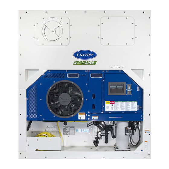
- Page 1 Container Refrigeration ANNUAL INSPECTION ThinLINE 69NT40-541 PrimeLINE 69NT40-561 Container Refrigeration Units 62-10327 Rev A...
- Page 3 ANNUAL INSPECTION ThinLINE 69NT40-541 PrimeLINE 69NT40-561 Container Refrigeration Units © 2017 Carrier Corporation Printed in USA June 2017 ●...
- Page 5 PURPOSE This manual has been written to assist owners and operators of Carrier Transicold MicroLink equipment in obtaining the maximum operating life from the equipment. It is written as an annual maintenance guide for ThinLINE and PrimeLINE units and it is recommended that all units are serviced with these procedures annually to obtain maximum operating time from the equipment.
- Page 6 (CB1 and CB2 if equipped) and unplug the unit from main power. Apply a locking device to ensure the system cannot be plugged in during the maintenance procedure. 2. Carrier Transicold recommends wearing the appropriate safety equipment such as safety glasses, gloves, etc. whenever working on refrigeration equipment. Personnel...
- Page 7 UNIT MODEL NUMBER The Model/Serial Number plate provides the unit model number (Refer to Figure Figure 2 Model/Serial Number plate 62-10327...
- Page 8 Figure 3 Evaporator Coil Figure 4 Evaporator Fan Blade 62-10327...
- Page 9 PHYSICAL INSPECTION Rear of Unit 1. Remove the upper internal access panel, remove any debris, and rinse the rear of unit with low pressure water. This includes the evaporator coil (Refer to Figure 2. Examine the evaporator motors for excessive end play. Slowly spin the evaporator fan blade and feel for any bearing drag.
- Page 10 7. Examine the drain cup, drain funnel and drain gutters. Repair as required. 8. Clean the defrost drain lines using a low pressure water hose to flush debris contained in the drain (Refer to Figure 6), and check that the water is running freely to the outside. Figure 6 Defrost Drain 9.
- Page 11 Figure 7 TXV Figure 8 EEV Figure 9 ETS1 and ETS2 62-10327...
- Page 12 10. Examine the Evaporator coil: a. Clean with low pressure water. If the evaporator coil is noted to have green patina or white powder, it is recom- mended to wash the coil with cleaner P/N NU4371-88. Refer to TechLINE December 2010 issue for Evaporator Section Cleaning.
- Page 13 12. Examine the heater termination thermostat (HTT) for proper positioning/damage (Refer to Figure 11). Replace as necessary. Figure 11 Heater Termination Thermostat 13. Examine internal valves, solenoid coils, as required per unit model number checking for proper positioning, physical damage, leaks or corrosion.
- Page 14 Front of Unit Refer to the Warnings and Notes section in this manual before proceeding with these instructions. Remove All Exterior Panels 1. Examine unit for traces of oil residue. Leak check the unit, includ- ing the compressor, using an electronic leak detector. Leaks are typically found as a dirty/oily residue on compressor joints, high pressure switch connection, pressure transducers (if fitted), piping connections etc.
- Page 15 3. Ensure that the remote monitoring and interrogation sockets are secure and free from damage and corrosion and caps are properly tethered to the unit (Refer to Figure 13). Repair/replace as required. Figure 13 Interrogation Socket 4. Inspect the compressor and mounting plate for severe corrosion, and check compressor shock mount for damage (cracks).
- Page 16 Figure 14 Electrical Control Box 6. Examine condenser motor and fan blade: a. Check for cracking or wear on the fan blade. Replace as necessary. b. Check for proper fan positioning in the venturi, refer to the operation & service manual for proper positioning instruc- tions.
- Page 17 Figure 15 Flat Condenser Coil Flat condenser coil Figure 16 C Condenser Coil C condenser coil 62-10327...
- Page 18 8. Examine the flexible condensate defrost drain tube (Refer to Figure 17). The tube should be undamaged and free from blockage or debris. It may be necessary to remove the condenser fan for complete access. Figure 17 Condensate Defrost Drain Tube Model/Serial Number plate Flexible condensate defrost drain tube 9.
- Page 19 11. Examine the water-cooled condenser (if equipped, refer to Figure 19): a. Periodic paint touch up of the water-cooled condenser may be required. b. Determine whether the water-cooled condenser is scaled. Refer to the operation & service manual for specific details on cleaning and maintenance of the water-cooled condenser.
- Page 20 12. Examine power cables: a. Check the cable to make sure it is securely attached to the unit and the clamp is in position. b. Replace or repair the cable if damaged or crushed in any man- ner. Replace the cable if more than one repair joint is found. c.
- Page 21 14. Remove left and right hand evaporator access panels. Ensure the evaporator motor mounting brackets or the evaporator motor stator brackets are properly torqued. Refer to the operation & service manual for specific torque values. Locating operation & service manuals is explained in the Purpose section.
- Page 22 OPERATIONAL INSPECTION Refer to Warnings and Notes on page 2 before proceeding. 1. Remove the Lock Out/Tag Out device and plug unit in to power supply. Check that voltage is good on all 3 phases. 2. Install the manifold gauge set using good system hygiene practices. For PrimeLINE units, operating pressures can be viewed by going to code 12 (Suction Pressure) and code 14 (Discharge Pressure).
- Page 23 5. Enter a DataCORDER Trip Start (Refer to Figure 23). Consult the instruction label on the face of the unit for correct procedure. Figure 23 DataCORDER Trip start 6. Check the discharge and suction pressures on manifold gauge set (or through codes), consult the operation &...
- Page 24 Figure 24 PTI Tests 10. Check the unit’s TXV and EEV superheat setting. Consult the operation & service manual for the correct superheat setting and procedure. Valve settings should not be adjusted if incorrect superheat is observed then the valve or sensors must be replaced. Note: For PrimeLINE units, the superheat can be observed at code 54.
- Page 25 Figure 25 Condenser Receiver Refrigerant level will be within range if the bottom sight glass is full and the top sight glass is empty Moisture indicator 13. Inspect water fittings on the water-cooled condenser (if equipped) for damage. Pressurize connections and record value of water pressure switch cut-out and cut-in.
- Page 27 INDEX Condenser Coil 12 Power Cables 16 Condenser Motor and Fan Blade 12 Container Carrier Transicold website 1 Rear of Unit 5 Refrigerant Level 19 DataBANK Download 21 Remote Monitoring and Interrogation Sockets 11 DataCORDER Trip Start 19 Defrost Drain Lines 6...
- Page 30 A part of UTC Building & Industrial Systems, a business unit of United Technologies Corporation. Stock symbol UTX. Carrier Transicold P.O. Box 4805 Syracuse, NY 13221 USA www.carrier.transicold.com...