Table of Contents
Advertisement
Installation, Operation,
and Maintenance
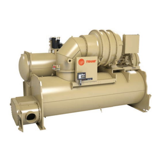
CVHH Water-Cooled CenTraVac™ ™ Chillers
With Tracer® AdaptiView™ Control
CVHH
Only qualified personnel should install and service the equipment. The installation, starting up, and servicing of heating, ventilating, and
air-conditioning equipment can be hazardous and requires specific knowledge and training. Improperly installed, adjusted or altered
equipment by an unqualified person could result in death or serious injury. When working on the equipment, observe all precautions in the
literature and on the tags, stickers, and labels that are attached to the equipment.
February 2018
S S A A F F E E T T Y Y W W A A R R N N I I N N G G
C C V V H H H H - - S S V V X X 0 0 0 0 1 1 G G - - E E N N
X39641257007
Advertisement
Table of Contents

Related Manuals for Trane CVHH CenTraVac


Summary of Contents for Trane CVHH CenTraVac
- Page 1 Installation, Operation, and Maintenance CVHH Water-Cooled CenTraVac™ ™ Chillers With Tracer® AdaptiView™ Control CVHH X39641257007 S S A A F F E E T T Y Y W W A A R R N N I I N N G G Only qualified personnel should install and service the equipment.
- Page 2 ( ( S S D D S S ) ) a a n n d d O O S S H H A A g g u u i i d d e e l l i i n n e e s s f f o o r r p p r r o o p p e e r r P P P P E E . . impact to the environment. Trane advocates the •...
- Page 3 I I n n t t r r o o d d u u c c t t i i o o n n W W A A R R N N I I N N G G W W A A R R N N I I N N G G F F o o l l l l o o w w E E H H S S P P o o l l i i c c i i e e s s ! ! R R e e f f r r i i g g e e r r a a n n t t M M a a y y B B e e U U n n d d e e r r P P o o s s i i t t i i v v e e P P r r e e s s s s u u r r e e ! !
- Page 4 • Start-up must be performed by Trane or an agent of Trane specifically authorized to perform startup and warranty of Trane® products. Trane, or an agent of Trane specifically authorized to perform start-up and warranty of Trane®...
-
Page 5: Table Of Contents
Installation: Mechanical ....22 Trane RuptureGuard ..... 39 General Information. - Page 6 Sensor Circuits ......74 CWR—Outdoor Option ....76 Trane-supplied Remote Starter Optional Control and Output Wiring .
- Page 7 Evaporator ......109 Trane ........121 Waterbox and Tubesheet Protective Coatings .
-
Page 8: Unit Nameplate
Unit Nameplate The unit nameplate is located on the left side of the Figure 1. Typical unit nameplate control panel. A typical unit nameplate is illustrated in the following figure and contains the following information: • Unit model and size descriptor •... -
Page 9: Compressor Nameplate
“CCHH” and the nameplate is located on the foot MODEL NO. of the volute. SERIAL NO. SALES ORDER TRANE MADE IN USA X39002458010B N N o o t t e e : : The serial number space on the compressor nameplate will be intentionally left blank. - Page 10 U U n n i i t t N N a a m m e e p p l l a a t t e e Figure 4. PED nameplate (all dimensions are metric) CD-001 CENTERED 2735 50,8 50,8 12,7 1131 DETAIL A ECONOMIZER...
-
Page 11: Model Number Descriptions
Model Number Descriptions CVHH CenTraVac Chiller Description CCHH Centrifugal Compressor Digit 32 — Control: Enhanced Protection Description Digit 1, 2 — Simplex CenTraVac™ ™ Chiller The compressor assembly has a separate Digit 33 — Control: Extended Operation model number which is required to identify internal and external compressor parts. -
Page 12: Pre-Installation
If the charge has This typically includes: escaped, contact your local Trane sales office for • A refrigerant monitor or detector that is capable of instructions. -
Page 13: Installation Requirements And Contractor Responsibilities
Meet foundation requirements • Safety chains Rigging • Clevis connectors • Lifting beam • Trane will perform or have direct on-site supervision Disassembly/Reassembly of the disassembly and (as required) reassembly work (contact your local Trane office for pricing) • Isolation pads or spring isolators •... -
Page 14: Storage Requirements
Start-up must be performed by Trane or an agent of Trane specifically authorized to perform start-up and warranty of Trane® products. Contractor shall provide Trane (or an agent of Trane specifically authorized to perform start-up) with notice of the scheduled start-up at least two weeks prior to the scheduled start-up. - Page 15 If no oil analysis program has been followed, replace oil prior to start-up If the chiller will be stored for more than six months after production, contact your local Trane Service Agency for required extended storage actions to minimize impact to the chiller and preserve the warranty.
-
Page 16: Unit Components
P P r r e e - - I I n n s s t t a a l l l l a a t t i i o o n n Unit Components Figure 6. Typical CVHH CenTraVac™ ™ chiller N N o o t t e e : : The control panel side of the unit is always designated as the front side of the unit. -
Page 17: Unit Clearances And Weights
Unit Clearances and Weights Recommended Unit Clearances • Use a housekeeping pad to provide better service clearances; refer to submittal for more information. Adequate clearances around and above the chiller are Per National Electric Code (NEC) Article 110: Unit required to allow sufficient access for service and mounted starters from 0 to 600V require a 42 inch maintenance operations. -
Page 18: General Weights
I I m m p p o o r r t t a a n n t t : : The weight information provided here should be used for general information only. Trane does not recommend using this weight information for considerations relative to chiller handling, rigging, or placement. -
Page 19: Weights (Kg)
I I m m p p o o r r t t a a n n t t : : The weight information provided here should be used for general information Wye-delta Low Voltage (less than 600 volts) only. Trane does not recommend using this Solid State weight information for considerations 900 amp... - Page 20 U U n n i i t t C C l l e e a a r r a a n n c c e e s s a a n n d d W W e e i i g g h h t t s s Table 5.
- Page 21 U U n n i i t t C C l l e e a a r r a a n n c c e e s s a a n n d d W W e e i i g g h h t t s s Table 7.
-
Page 22: Installation: Mechanical
I I m m p p o o r r t t a a n n t t : : Trane will not assume responsibility for compressor and the lifting beam. - Page 23 I I n n s s t t a a l l l l a a t t i i o o n n : : M M e e c c h h a a n n i i c c a a l l 4.
-
Page 24: Special Lift Requirements
N N o o t t e e : : Disassembly and reassembly work includes dowel-pinning the compressor and removing C = 9 in. (228.6 mm) it from the unit. Contact Trane or an agent of Remember that the chiller must be level within 1/16 in. Trane specifically authorized to perform start- up and warranty of Trane ®... - Page 25 I I n n s s t t a a l l l l a a t t i i o o n n : : M M e e c c h h a a n n i i c c a a l l Figure 10.
-
Page 26: Leveling The Unit
I I n n s s t t a a l l l l a a t t i i o o n n : : M M e e c c h h a a n n i i c c a a l l 4. - Page 27 I I m m p p o o r r t t a a n n t t : : Immediately report any unit damage method to level the unit. incurred during handling or installation at the job site to the Trane sales office. CVHH-SVX001G-EN...
-
Page 28: Installation: Water Piping
I I m m p p o o r r t t a a n n t t : : Trane strongly recommends using the To determine whether or not pressure relief valves... -
Page 29: Required Flow-Sensing Devices
I I n n s s t t a a l l l l a a t t i i o o n n : : W W a a t t e e r r P P i i p p i i n n g g Install a strainer in the entering side of each piping from the control panel must not exceed 29.5 ft (9 m) circuit to avoid possible tube plugging in the chiller... -
Page 30: Evaporator And Condenser Water
N N o o t t e e : : The “Temp” potentiometer on the ifm (typical) water piping arrangements for the evaporator efector ® control module has no effect in and condenser. Trane application. It is NOT necessary to make adjustments to the “Temp” potentiometer. 8. After the cutout setting is adjusted, the cutout setpoint will be indicated with a yellow light on the Flow Control Monitor LED bar graph display. -
Page 31: Piping
Expenses that result from a failure to may be installed in either the entering or leaving leg follow this recommendation will NOT be paid by Trane. of the chilled water circuit. Water piping connection sizes and components are 8. -
Page 32: Water Piping Connections
(i.e., drainage, etc.). N N o o t t e e : : If needed, plug-type sensor extension cables are available for purchase from Trane Parts Service. These sensor extension cables may be necessary if the waterboxes are changed or if the temperature sensors are moved out into the unit piping for better mixed temperature readings. -
Page 33: Grooved Pipe Coupling
Figure 18. Customer piping connection types to attenuate vibration and prevent stress at the waterbox connections. Flange adapters are not Flanged Victaulic® provided for CVHH CenTraVac™ chillers with 300 psig Waterbox Waterbox (2068.4 kPaG) waterboxes that have 14 in. (355.6 mm) and larger piping connections. -
Page 34: Victaulic Gasket Installation
I I n n s s t t a a l l l l a a t t i i o o n n : : W W a a t t e e r r P P i i p p i i n n g g N N O O T T I I C C E E configuration. -
Page 35: Screw-Tightening Sequence For Water
I I n n s s t t a a l l l l a a t t i i o o n n : : W W a a t t e e r r P P i i p p i i n n g g Screw-Tightening Sequence for for the appropriate pattern as shown in the following figure. -
Page 36: Vent Piping
NOT to balanced relief piping such as PVC, ensure that both the pipe valves, rupture members (as used on Trane® material and the adhesive have been tested for centrifugal chillers), fusible plugs, or pilot-operated refrigerant compatibility. -
Page 37: Vent Line Installation
V V e e n n t t P P i i p p i i n n g g N N o o t t e e : : The tables and figures in “Vent Line Sizing • When attaching the vent line to the chiller, do NOT Reference,”... - Page 38 V V e e n n t t P P i i p p i i n n g g Figure 24. Rupture disk location and cross section of rupture disk Gasket Outside pipe assembly X39003892001A N N o o t t e e : : Graphic labels (shown above) are used for CE application only.
-
Page 39: Trane Ruptureguard
F F a a i i l l u u r r e e t t o o f f o o l l l l o o w w i i n n s s t t r r u u c c t t i i o o n n s s b b e e l l o o w w c c o o u u l l d d r r e e s s u u l l t t i i n n The Trane RuptureGuard™ refrigerant containment e e q q u u i i p p m m e e n n t t d d a a m m a a g g e e . -
Page 40: Vent Line Sizing Reference
MUST be installed properly. Failure to and (1) relief device. properly install the RuptureGuard ™ will likely result in a start-up delays and required rework and expenses that result from a failure to properly install the RuptureGuard ™ will NOT be paid by Trane. CVHH-SVX001G-EN... - Page 41 V V e e n n t t P P i i p p i i n n g g Figure 28. Rupture disk vent pipe sizing (IP units); for use with preceding table Pipe size as a Function of “C” Value and Length of Run 1000 Pipe Size (I.D.) Friction Factor...
- Page 42 V V e e n n t t P P i i p p i i n n g g ASHRAE Standard 15 Table 14. “C” values used to determine rupture disk vent line sizes (kg/s); for use with the following figure 0.214d –...
- Page 43 V V e e n n t t P P i i p p i i n n g g Figure 29. Rupture disk vent pipe sizing (SI units); for use with preceding table Pipe size as a Function of “C” Value and Length of Run Pipe Size (I.D.) Friction Factor 150 DN...
- Page 44 V V e e n n t t P P i i p p i i n n g g ASHRAE Standard 15 • f = Moody friction factor in fully turbulent flow • d = inside diameter of pipe or tube, mm –15 7.4381x10 –...
-
Page 45: Insulation
Factory Applied Insulation insulation; contact Trane for further review. All low-temperature surfaces are covered with 3/4 in. N N o o t t e e : : If the unit is not factory-insulated, install (19.05 mm) Armaflex®... - Page 46 I I n n s s u u l l a a t t i i o o n n Figure 30. Recommended area for unit insulation Line to eductor Line from evaporator Filter drier and eductor lines Suction Pipe (free cooling only) cover Suction elbow...
-
Page 47: Installation: Controls
Installation: Controls This section covers information pertaining to the UC800 controller hardware. For information about the Tracer® AdaptiView™ display, which is used to interface with the internal chiller data and functions provided by the UC800, refer to Tracer AdaptiView Display for Water-Cooled CenTraVac Chillers Operations Guide (CTV-SVU01*-EN). -
Page 48: Communication Interfaces
I I n n s s t t a a l l l l a a t t i i o o n n : : C C o o n n t t r r o o l l s s Figure 31. - Page 49 I I n n s s t t a a l l l l a a t t i i o o n n : : C C o o n n t t r r o o l l s s Figure 32.
- Page 50 I I n n s s t t a a l l l l a a t t i i o o n n : : C C o o n n t t r r o o l l s s Figure 33.
-
Page 51: Installing The Tracer Adaptiview
Figure 34. Tracer® ® AdaptiView™ ™ shipping location I I m m p p o o r r t t a a n n t t : : For best results, Trane, or an agent of Trane, must install the Tracer ®... -
Page 52: Arm
I I n n s s t t a a l l l l a a t t i i o o n n : : C C o o n n t t r r o o l l s s Figure 36. -
Page 53: Electrical Requirements
Electrical Requirements Installation Requirements • power supply wiring to the starter, • other unit control options present, and W W A A R R N N I I N N G G • any field-supplied control devices. P P r r o o p p e e r r F F i i e e l l d d W W i i r r i i n n g g a a n n d d G G r r o o u u n n d d i i n n g g As you review this manual along with the wiring R R e e q q u u i i r r e e d d ! ! instructions presented in this section, keep in mind... - Page 54 E E l l e e c c t t r r i i c c a a l l R R e e q q u u i i r r e e m m e e n n t t s s •...
-
Page 55: Wiring
-installed. Refer to submittal and ship-with wiring schematics for voltage requirements. Must be separated from 120 Vac and higher wiring. The maximum distance a Trane–supplied remote starter can be placed from the chiller is 1000 ft (305 m). CVHH-SVX001G-EN... -
Page 56: Wiring
, refer to the table in “Electrical Requirements,” p. Starter by Others Specification available from your local Trane sales office. Wires, lugs, and fuses/breakers are sized based on National Electric Code (NEC) [NFPA 70] and UL 1995. Refer to submittal and ship-with wiring schematics for voltage requirements. -
Page 57: Current Transformer And Potential
C C u u s s t t o o m m e e r r - - s s u u p p p p l l i i e e d d R R e e m m o o t t e e S S t t a a r r t t e e r r W W i i r r i i n n g g Current Transformer and Table 21. -
Page 58: Power Supply Wiring
Power Supply Wiring W W A A R R N N I I N N G G • Verify that the starter nameplate ratings are compatible with the power supply characteristics P P r r o o p p e e r r F F i i e e l l d d W W i i r r i i n n g g a a n n d d G G r r o o u u n n d d i i n n g g and with the electrical data on the unit nameplate. -
Page 59: Circuit Breakers And Fused
L1 L2 L3 G all customer wiring needs to be run in conduit. Any Ethernet cables being used by customer to interface with the Trane® chiller must be shielded Ethernet cabling. The customer is required to provide an overcurrent device upstream of the CPTR option in accordance with... -
Page 60: Ce For Starter Or Drive
All Trane-supplied remote starters and customer wiring needs to be run in conduit. drives used in conjunction with CVHH For remote starters interfacing with the Trane® chiller, Trane ® chillers will be CE-compliant per all wiring needs to be run in conduit. Any Ethernet... -
Page 61: Control Power Transformer
The standard unit-mounted CPTR option shall have an enclosure with a disconnect and will require customer- supplied power. CVHH CenTraVac™ chillers have a low-voltage CPTR option and a medium-voltage CPTR option. The CPTR option involves a single phase 4kVA transformer(s) and the oil pump motor circuit to be located together in an enclosure that is unit-mounted. - Page 62 P P o o w w e e r r S S u u p p p p l l y y W W i i r r i i n n g g N N o o t t e e s s : : Figure 39.
-
Page 63: Interconnecting Wiring
P P o o w w e e r r S S u u p p p p l l y y W W i i r r i i n n g g Figure 40. Option 2—PFCC wires routed through current transformers Fused Disconnect... -
Page 64: Starter To Motor Wiring
P P o o w w e e r r S S u u p p p p l l y y W W i i r r i i n n g g Figure 41. Typical equipment room layout for units Figure 42. -
Page 65: Terminal Clamps
Install but do NOT connect the power leads between the starter and compressor motor. (These connections will be completed under supervision of a qualified Trane service engineer after the pre-start inspection.) X39003892001A N N o o t t e e : : Graphic labels (shown above) are used for CE application only. -
Page 66: Bus Bars
. . 18 AWG for runs up to 1000 ft (304.8 m). For Bus bars and extra nuts are available as a Trane option. AWG/MCM equivalents in mm... - Page 67 P P o o w w e e r r S S u u p p p p l l y y W W i i r r i i n n g g W W A A R R N N I I N N G G I I m m p p o o r r t t a a n n t t : : •...
-
Page 68: Medium Voltage Motor
N N o o t t e e : : Trane assumes no responsibility for the design, documentation, construction, compatibility, installation, start-up, or long term support of starters provided by others. -
Page 69: Motor Supply Wiring
/ / n n a a t t i i o o n n a a l l e e l l e e c c t t r r i i c c a a l l c c o o d d e e s s . . trays. To limit the effects of corona or ionization with cables carrying more than 2000V, Trane requires that the power cable have a metallic shield, unless the cable is specifically listed or approved for non-shielded use. -
Page 70: Ground Wire Terminal Lug
M M e e d d i i u u m m V V o o l l t t a a g g e e M M o o t t o o r r CE for Medium Voltage Starter Follow all instructions provided with the field-provided lugs to ensure proper connections. - Page 71 M M e e d d i i u u m m V V o o l l t t a a g g e e M M o o t t o o r r I I m m p p o o r r t t a a n n t t : : •...
-
Page 72: Wiring)
System Control Circuit Wiring (Field Wiring) Table 24. Unit control panel wiring 120 Vac Standard Control Circuits: Unit Control Panel Control Wiring Input or Output Type Unit Control Terminations Contacts (120 Vac) Chilled Water Flow Proving Input Binary Input Normally Open, Closure with Flow 1X1-5 to 1K16-J3-2 Condenser Water Flow Proving Binary Input... -
Page 73: Switch Input
S S y y s s t t e e m m C C o o n n t t r r o o l l C C i i r r c c u u i i t t W W i i r r i i n n g g ( ( F F i i e e l l d d W W i i r r i i n n g g ) ) Table 24. -
Page 74: Condenser Water Proof Of Flow
S S y y s s t t e e m m C C o o n n t t r r o o l l C C i i r r c c u u i i t t W W i i r r i i n n g g ( ( F F i i e e l l d d W W i i r r i i n n g g ) ) panel to control the condenser pump. - Page 75 S S y y s s t t e e m m C C o o n n t t r r o o l l C C i i r r c c u u i i t t W W i i r r i i n n g g ( ( F F i i e e l l d d W W i i r r i i n n g g ) ) Figure 45.
-
Page 76: Cwr-Outdoor Option
(115 Vac) be utilized to The sensor will be configured (given its identity and power up the control circuits. become functional) at start-up when the Trane service Use the as-built starter schematic to ensure correct technician performs the start-up configuration. It will fuse and terminals. -
Page 77: Operating Principles
CenTraVac™ chiller. If mechanical problems do occur, however, contact a Trane service technician Condenser to ensure proper diagnosis and repair of the unit. Compressor I I m m p p o o r r t t a a n n t t : : Although CenTraVac ™... -
Page 78: Oil And Refrigerant Pump
O O p p e e r r a a t t i i n n g g P P r r i i n n c c i i p p l l e e s s Oil and Refrigerant Pump compression (refer to the following figure). - Page 79 O O p p e e r r a a t t i i n n g g P P r r i i n n c c i i p p l l e e s s Figure 50. Oil refrigerant pump Compressor lubrication system Motor cooling system Oil reclaim system...
- Page 80 O O p p e e r r a a t t i i n n g g P P r r i i n n c c i i p p l l e e s s C C A A U U T T I I O O N N H H o o t t S S u u r r f f a a c c e e ! ! F F a a i i l l u u r r e e t t o o f f o o l l l l o o w w i i n n s s t t r r u u c c t t i i o o n n s s b b e e l l o o w w c c o o u u l l d d r r e e s s u u l l t t i i n n m m o o d d e e r r a a t t e e i i n n j j u u r r y y .
-
Page 81: Motor Cooling System
O O p p e e r r a a t t i i n n g g P P r r i i n n c c i i p p l l e e s s Oil supply to both the thrust bearing and journal close. - Page 82 O O p p e e r r a a t t i i n n g g P P r r i i n n c c i i p p l l e e s s 1. Purge tank 2.
- Page 83 O O p p e e r r a a t t i i n n g g P P r r i i n n c c i i p p l l e e s s 1. Regeneration solenoid valve 2.
- Page 84 O O p p e e r r a a t t i i n n g g P P r r i i n n c c i i p p l l e e s s refrigeration system and generate a non-latching A temperature sensor is installed through the top of the diagnostic—Purge Liquid Level Too High Warning.
- Page 85 O O p p e e r r a a t t i i n n g g P P r r i i n n c c i i p p l l e e s s tank heater, the regeneration solenoid valve, and an used to control the pump-out solenoid valve and alarm output.
-
Page 86: Start-Up And Shut-Down
Start-up and Shut-down This section provides basic information on chiller • The first line of text in the circles are the visible top operation for common events. level operating modes that can be displayed in Tracer® AdaptiView™. Sequence of Operation •... -
Page 87: Start-Up Sequence Of Operation
S S t t a a r r t t - - u u p p a a n n d d S S h h u u t t - - d d o o w w n n •... - Page 88 S S t t a a r r t t - - u u p p a a n n d d S S h h u u t t - - d d o o w w n n shall be energized to cool the oil.
- Page 89 S S t t a a r r t t - - u u p p a a n n d d S S h h u u t t - - d d o o w w n n Figure 54.
-
Page 90: Power Up Diagram
S S t t a a r r t t - - u u p p a a n n d d S S h h u u t t - - d d o o w w n n Figure 55. - Page 91 S S t t a a r r t t - - u u p p a a n n d d S S h h u u t t - - d d o o w w n n Figure 56.
-
Page 92: Free Cooling Cycle
S S t t a a r r t t - - u u p p a a n n d d S S h h u u t t - - d d o o w w n n Figure 57. -
Page 93: Hot Water Control
S S t t a a r r t t - - u u p p a a n n d d S S h h u u t t - - d d o o w w n n Hot Water Control In Hot Water Temperature Control, the softloading pulldown rate limit operates as a softloading pullup... -
Page 94: Unit Start-Up And Shut-Down
S S t t a a r r t t - - u u p p a a n n d d S S h h u u t t - - d d o o w w n n •... -
Page 95: Daily Unit Start-Up
S S t t a a r r t t - - u u p p a a n n d d S S h h u u t t - - d d o o w w n n to the chilled water setpoint. -
Page 96: Daily Unit Shut-Down
Operation,” p. 106 (tables for recommended Adaptive mode customizes the purge refrigeration maintenance of standard and optional features) circuit operation during two distinct chiller operating should be performed by qualified Trane service conditions: technicians. • Chiller compressor On N N o o t t e e : : During extended shut-down periods, be sure to •... - Page 97 S S t t a a r r t t - - u u p p a a n n d d S S h h u u t t - - d d o o w w n n •...
- Page 98 S S t t a a r r t t - - u u p p a a n n d d S S h h u u t t - - d d o o w w n n During the purge refrigeration circuit Off cycle, the time If the chiller compressor is turned Off, the purge remaining is displayed as Time Until Next Purge Run in...
- Page 99 S S t t a a r r t t - - u u p p a a n n d d S S h h u u t t - - d d o o w w n n Pumpout Time with chiller On or Off •...
-
Page 100: Air Removal
S S t t a a r r t t - - u u p p a a n n d d S S h h u u t t - - d d o o w w n n Figure 60. -
Page 101: Carbon Tank And Regeneration
S S t t a a r r t t - - u u p p a a n n d d S S h h u u t t - - d d o o w w n n When sufficient non-condensables have accumulated N N o o t t e e : : For purge systems equipped with standard in the purge tank to decrease the compressor suction... - Page 102 S S t t a a r r t t - - u u p p a a n n d d S S h h u u t t - - d d o o w w n n Remaining carbon capacity% = 100 - (pump-out minutes since last regen/pump-out minutes at 100% capacity)*100...
- Page 103 S S t t a a r r t t - - u u p p a a n n d d S S h h u u t t - - d d o o w w n n testing purposes.
- Page 104 S S t t a a r r t t - - u u p p a a n n d d S S h h u u t t - - d d o o w w n n the past seven days that occurred while the chiller •...
-
Page 105: Recommended Maintenance
ASME SA-193M GRADE B7, ZINC PLATED. D D o o n n o o t t s s u u b b s s t t i i t t u u t t e e ! ! Contact your local Trane representative for replacement bolts. -
Page 106: Normal Operation
R R e e c c o o m m m m e e n n d d e e d d M M a a i i n n t t e e n n a a n n c c e e logs can be reviewed to identify any developing trends condensing pressure during a month’s time, she can in the chiller’s operating conditions. -
Page 107: Recommended Compressor Oil
Trane annual oil analysis program rather than automatically change the N N o o t t e e : : Use only Trane OIL00022 compressor oil. A full oil as part of scheduled maintenance. Change the oil oil change is 21 gallons (79.5 L). -
Page 108: Leak Testing
. . I I m m p p o o r r t t a a n n t t : : If leak testing is required, contact a Trane Service Agency. -
Page 109: Recommended System
Valves Waterbox and Tubesheet Protective Coatings Trane recommends that coated waterboxes/tubesheets —regardless of the type of protective coating included —be taken out of service within the first one to three Cleaning months of operation for inspection. Any voids or Solution defects identified upon inspection must be repaired. -
Page 110: Ruptureguard Maintenance
F F a a i i l l u u r r e e t t o o f f o o l l l l o o w w i i n n s s t t r r u u c c t t i i o o n n s s b b e e l l o o w w c c o o u u l l d d r r e e s s u u l l t t i i n n replacement every two to three years. Trane... -
Page 111: Cvhh-Svx001G-En
R R e e c c o o m m m m e e n n d d e e d d M M a a i i n n t t e e n n a a n n c c e e Figure 64. -
Page 112: Cvhh-Svx001G-En
R R e e c c o o m m m m e e n n d d e e d d M M a a i i n n t t e e n n a a n n c c e e 3. -
Page 113: Installation
1. Determine the type and size of chiller being serviced. Refer to Trane® nameplate located on Discussion chiller control panel. I I m m p p o o r r t t a a n n t t : : This section contains rigging and lifting This section will discuss recommended lifting. -
Page 114: Reassembly
W W a a t t e e r r b b o o x x R R e e m m o o v v a a l l a a n n d d I I n n s s t t a a l l l l a a t t i i o o n n Reassembly Figure 65. - Page 115 W W a a t t e e r r b b o o x x R R e e m m o o v v a a l l a a n n d d I I n n s s t t a a l l l l a a t t i i o o n n Table 30.
-
Page 116: Screw-Tightening Sequence For Waterboxes
W W a a t t e e r r b b o o x x R R e e m m o o v v a a l l a a n n d d I I n n s s t t a a l l l l a a t t i i o o n n Table 31. -
Page 117: Heat Recovery Condenser Waterbox
W W a a t t e e r r b b o o x x R R e e m m o o v v a a l l a a n n d d I I n n s s t t a a l l l l a a t t i i o o n n Figure 67. -
Page 118: Appendix A: Forms And Check
I I m m p p o o r r t t a a n n t t : : Start-up must be performed by Trane or an order number is also listed. -
Page 119: Appendix B: Centravac™ Chiller
I I m m p p o o r r t t a a n n t t : : Start-up must be performed by Trane or an CenTraVac™ chiller agent of Trane specifically authorized to Pumps perform start-up and warranty of Trane ®... - Page 120 6. T T e e s s t t i i n n g g Dry nitrogen available for pressure testing (for This is to certify that the Trane equipment has been disassembled units) properly and completely installed, and that the...
-
Page 121: Appendix C: Cvhh Centravac™ Chiller
Appendix C: CVHH CenTraVac™ ™ Chiller Start-up Tasks to be Performed by Trane W W A A R R N N I I N N G G N N o o t t e e : : All conditions which do not conform to the... - Page 122 A A p p p p e e n n d d i i x x C C : : C C V V H H H H C C e e n n T T r r a a V V a a c c ™ ™ C C h h i i l l l l e e r r S S t t a a r r t t - - u u p p T T a a s s k k s s t t o o b b e e P P e e r r f f o o r r m m e e d d b b y y T T r r a a n n e e pressure.
-
Page 123: Appendix D: Cvhh Centravac™ Chiller
Appendix D: CVHH CenTraVac™ ™ Chiller Annual Inspection List Follow the annual maintenance instructions provided Verify control parameters. in the text of this manual, including but not limited to: Test appropriate sensors for accuracy. 1. C C o o m m p p r r e e s s s s o o r r / / M M o o t t o o r r Ensure sensors are properly seated in wells with Motor continuity. -
Page 124: Appendix E: Cvhh Centravac™ Chiller
Appendix E: CVHH CenTraVac™ ™ Chiller Operator Log Water-Cooled CVHH CenTraVac™ ™ Chillers with UC800 Controller Tracer® ® AdaptiView™ ™ Reports—Log Sheet Log 1 Log 2 Log 3 Evaporator Entering Leaving Saturated Refrig. Press Approach Flow Sw Status Condenser Entering... - Page 125 A A p p p p e e n n d d i i x x E E : : C C V V H H H H C C e e n n T T r r a a V V a a c c ™ ™ C C h h i i l l l l e e r r O O p p e e r r a a t t o o r r L L o o g g Water-Cooled CVHH CenTraVac™ ™ Chillers with UC800 Controller Tracer®...
- Page 126 N N o o t t e e s s CVHH-SVX001G-EN...
- Page 127 N N o o t t e e s s CVHH-SVX001G-EN...
- Page 128 ® , Thermo King ® Trane ® — work together to enhance the quality and comfort of air in homes and buildings; transport and protect food and perishables; and increase industrial productivity and efficiency. We are a global business committed to a world of sustainable progress and enduring results.