
Related Manuals for Trane CVGF-SVU02B-E4


Summary of Contents for Trane CVGF-SVU02B-E4
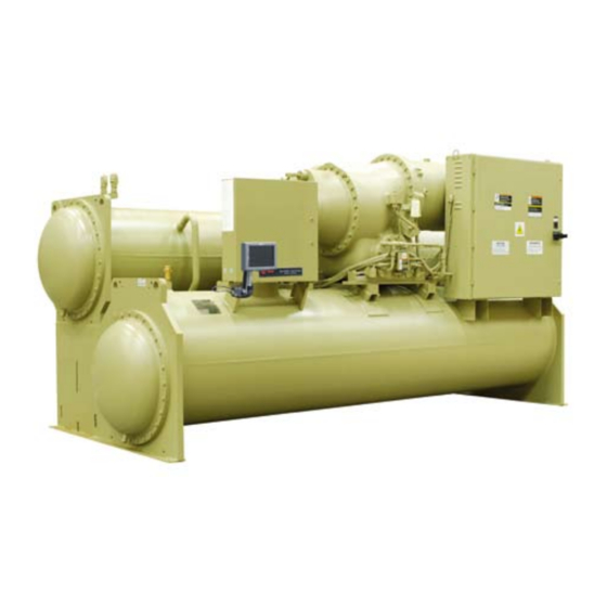
- Page 1 Operation Maintenance Manual Gear-Driven Centrifugal Water-Cooled Liquid Chillers with CH530 Controls Unit Model CVGF 400-1000 Ton Units (50 and 60 Hz) CVGF-SVU02B-E4 X39640691020...
-
Page 2: Warnings And Cautions
– Indicates a potentially hazardous situation which, if not avoided, may result in minor or moderate injury. It may also be used to alert against unsafe practices. CAUTION – Indicates a situation that may result in equipment or property-damage-only accidents. © 2005 American Standard Inc. All rights reserved. CVGF-SVU02B-E4... -
Page 3: Table Of Contents
Contents Warnings and Cautions General Information Unit Control Panel (UCP) Base Loading Control Algorithm Control System Components Machine Protection and Adaptive Unit Startup Unit Shutdown Periodic Maintenance CVGF-SVU02B-E4... -
Page 4: General Information
CVGF centrifugal chillers panel. equipped with the Tracer CH530 Chiller Controller system. Note: Trane starters are identified by a separate model Carefully review this information number found on the starter. and follow the instructions given to successfully operate and maintain a CVGF unit. - Page 5 IPC = Interprocessor RLA = Rated Load Amps Communication RTD = Resistive Temperature LCD = Liquid Crystal Display Device Tracer CH530= Controls LED = Light Emitting Diode Platform used on this Chiller TRMM = Tracer Communications UCP = Unit Control Panel CVGF-SVU02B-E4...
- Page 6 Figure 1. General CVGF unit component Unit-Mounted Starter (Optional) Two-Stage Compressor Condenser Relief Valves Evaporator Oil Pump Control Panel CH530 Unit Nameplate Figure 2. Component location for typical CVGF unit (back view) Motor Unit nameplate Relief valves Oil cooler Economizer CVGF-SVU02B-E4...
- Page 7 A schematic of the system showing refrigerant flow is given in Figure 4. Figure 3. P-H chart Condenser Compressor 2nd stage Economizer Compressor 1st stage Evaporator CVGF-SVU02B-E4...
- Page 8 Refrigeration This is accomplished by the system cooling load and heat of Effect from RE’ to RE. The Trane-patented falling film compression are rejected to the economizer provides around 4 evaporator design. The amount condenser water circuit. This...
- Page 9 Figure 4. Refrigerant flow diagram Starter Internal filter Compressor Inlet Gears vanes High lift Motor unloading Bearings valve Condenser (HLUV) Fixed Oil cooler orifice Condenser sump Strainer Economizer Oil sump Fixed orifice Pump Fixed orifice Distributor Refrigerant Flow Evaporator CVGF-SVU02B-E4...
- Page 10 See Figure 5. assembly is dynamically balanced for vibration of less than 5.1 mm/sec (0.2 ips peak velocities) at nominal operating speeds. The control system affords 20 to 100 percent capacity modulation by electrically actuated guide vanes upstream of each impeller. CVGF-SVU02B-E4...
- Page 11 General Information Figure 5. Compressor cross-section view Motor rotor Motor shaft Discharge end Bull gear Motor Motor terminal housing Motor stator Pinion shaft Gear housing 2nd stage impeller 1st stage impeller Oil pump Suction sump CVGF-SVU02B-E4...
- Page 12 TechView ™ visit Controls Operator Interface screen. Logically organized your local Trane Service Information is tailored to groups of information such as company, or The Trane operators, service technicians chiller modes of operation, Company’s website at and owners.
- Page 13 Figure 6. CVGF sequence of operation overview Stopped Power Up Stopped Run Inhibit Starting Stopping Auto Fast Restart or Satisfied Setpoint Preparing to Shut Waiting to Start Down Shutting Starting Down Compressor Stop Command or Diagnostic Running Running Running - Limit CVGF-SVU02B-E4...
- Page 14 Figure 7. Sequence of operation: power up Apply Control Power Completing Self Test (12 Seconds) Starting Application (20-30 Seconds*) Last Mode Such as Auto or Stopped as shown *Note: The variation in DynaView Power Up time is dependent on the number of installed options. CVGF-SVU02B-E4...
- Page 15 Information Figure 8. Sequence of operation: running Starter Status is Limit Mode Exit Limit Mode “Running” Starting Running Running - Limit Running Running Compressor Modulate IGV for Modulate IGV for Modulate IGV for LWT control Limit control LWT control CVGF-SVU02B-E4...
- Page 16 Evaporator pump off delay not performed for immediate shutdown De-energize compressor Confirm no compressor currents 8 seconds after compressor is de- energized De-energize condenser water pump *Note: No oil pressure when oil differential pressure switch is open. CVGF-SVU02B-E4...
- Page 17 Command IGV closed De-energize compressor 5 minutes after oil pump is de-energized Confirm no compressor currents within 30 seconds De-energize condenser water pump relay Enforce all running mode diagnostics *Note: No oil pressure when oil differential pressure switch is open. CVGF-SVU02B-E4...
- Page 18 Heater are never energized at the The oil temperature is at or same time. below the low oil temperature start inhibit setpoint. The heater is energized to raise the oil temperature. See Low Temperature Start Inhibit section for information about Enhanced Oil Temp Protection. CVGF-SVU02B-E4...
- Page 19 This pump is running so do not do check is made after post-lube is the check. complete to verify that the differential pressure has dropped to indicate no oil flow. CVGF-SVU02B-E4...
- Page 20 Low is idle and is implemented to oil circuit. Differential Oil Pressure Cutout recognize and ensure that the setpoint. pressure switch is operational and that it is open for a period of five minutes. CVGF-SVU02B-E4...
- Page 21 Information Figure 11. Oil circuit diagram Starter Internal Filter Compressor Gears ST 2 ST 1 Motor Condenser High Lift Bearings Unloading Valve (HLUV) Oil Cooler Condenser Sump Strainer Economizer Oil Sump Fixed Orifice Pump Fixed Orifice Refrigerant Distributor Evaporator CVGF-SVU02B-E4...
-
Page 22: Unit Control Panel (Ucp)
UCP ‘s operator interface and communication) bus allows the to the control system. main processor is called the communications between LLID’s DynaView ™ and is located on the UCP door. (See Operators interface section for detailed information) Figure 12. Control panel CVGF-SVU02B-E4... - Page 23 Tracer CH530 constantly receives information about key data parameters, temperatures and currents. Every five seconds a multiple objective algorithm compares each parameter to its programmed limit. The chiller’s Adaptive Control ™ capabilities maintain overall system performance by keeping its peak efficiency. CVGF-SVU02B-E4...
- Page 24 The “additional info” icon will flow switches. lube, performs post-lube, starts present a subscreen that lists in the compressor, performs water further detail the subsystem temperature control, establishes modes. limits, and pre-positions the inlet guide-vanes. Figure 13. DynaView ™ main processor CVGF-SVU02B-E4...
- Page 25 (non- changes by touching the up or front so it’s contents are visible condensing). The enclosure down arrows. includes a weather tight connection means for the RS232 TechView ™ connection. CVGF-SVU02B-E4...
- Page 26 ENTER and CANCEL keys. (While a setting is being changed, AUTO and STOP keys are recognized even if ENTER or CANCEL has not been pressed. Selecting the Auto key will enable the chiller for active cooling. CVGF-SVU02B-E4...
- Page 27 Additional information (if it exists) regarding the machine Figure 14. operating state will be available to the user by selecting the “additional information” button (double right arrow) next to the top-level operating mode. These sub-level modes are shown Table 1. CVGF-SVU02B-E4...
- Page 28 Compressor is running with no limits in effect. Running – Limit Compressor is running with limit in effect. Preparing To Shutdown Unit is closing inlet guide vanes prior to compressor shutdown. Shutting Down Compressor has been stopped and unit is performing shutdown tasks. Figure 15. CVGF-SVU02B-E4...
- Page 29 Running – Limit Minimum Capacity Limit Running – Limit Maximum Capacity Limit Preparing To Shutdown Closing IGV IGV Position % Shutting Down Post-Lubrication Time: MIN:SEC Shutting Down Evaporator Pump Off Delay: MIN:SEC Shutting Down Condenser Pump Off Delay: MIN:SEC CVGF-SVU02B-E4...
- Page 30 Evaporator Entering and Leaving Water Temperature Condenser Entering and Leaving Water Temperature Active Chilled Water Setpoint (>>source) Active Current Limit Setpoint (>>source), If enabled Active Base Loading Setpoint (>>source), If enabled Average Line Current Approximate Chiller Capacity, If option installed Software Version CVGF-SVU02B-E4...
- Page 31 The to the Stop key. A flashing cause a repeat failure. Contact manual override indicator would “alarm” indicates a machine local Trane Service for assistance reappear if such an override shutdown and a non flashing as necessary. exists.
- Page 32 In the second and external setpoints. column “- - - -” will be shown if that option is Not Installed, otherwise the current setpoint from that source will be shown. The “Back” button provides navigation back to the chiller screen. CVGF-SVU02B-E4...
- Page 33 Limit Setpoint will take the user to the active current limit setpoint sub-screen. The active current limit setpoint is that setpoint to which the unit is currently controlling. It is the result of arbitration between the front panel, BAS, and external setpoints. CVGF-SVU02B-E4...
- Page 34 °C or °F Evaporator Refrigerant Pressure Temperature °C or °F Condenser Refrigerant Pressure Psia or kPa Condenser Approach Temperature °C or °F Condenser Water Flow Switch Status Flow or No Flow Outdoor Air Temperature, If installed °C or °F CVGF-SVU02B-E4...
- Page 35 F/ C 18. Condenser Leaving Water Temperature F/ C 19. Condenser Saturated Refrigerant Temperature F/ C 20. Condenser Refrigerant Pressure PSIG / kPa 21. Condenser Approach Temperature F/ C 22. Condenser Water Flow Switch Status Flow / No Flow CVGF-SVU02B-E4...
- Page 36 Unit Control Panel (UCP) Setting Tab screens provides a Settings screen for standard CVGF: user the ability to adjust settings justified to support daily tasks. The layout provides a list of sub- menus, organized by typical subsystem. CVGF-SVU02B-E4...
- Page 37 1. Temperatures will be adjustable to 0.1 degree F or C. The Main Processor provides the minimum and maximum allowable value. 2. Adjustable to the nearest whole number percent. The Main Processor provides the minimum and maximum allowable value. CVGF-SVU02B-E4...
- Page 38 . Language shall always be the last setting listed on the Display Settings menu. This will allow a user to find language selection if looking at an unrecognizable language. 7. Manual Compressor Control allows an operator to override the Auto Control and manually control the compressor while in operation. This is not active during Stop mode. CVGF-SVU02B-E4...
- Page 39 The operator selects a setpoint to change by touching either the description or setpoint value. Doing this causes the screen to switch to the Analog Settings subscreen shown below. Note: Spin buttons used to change setpoint value. CVGF-SVU02B-E4...
- Page 40 Settings with buttons only (screen has no cancel or enter key) do accept the new selection immediately. Note: Radio 1 and Radio 2 refer to “touch sensitive buttons.” The labels depend upon the setting being controlled. Mode Override for Enumerated Settings is shown below: CVGF-SVU02B-E4...
- Page 41 Cancel Key will allow the user to Enter or Cancel the entry. Mode Override for Analog Settings is shown below: The date setpoint screen for setting up the is shown below: The user must select Day, Month, or Year and then use the up or down arrows to adjust. CVGF-SVU02B-E4...
- Page 42 Hour, or Minute and then use the up or down arrows to adjust. Adjusting hours will also adjust am and pm. Note: The 24 hour format setpoint screen is similar with the am and pm not shown. CVGF-SVU02B-E4...
- Page 43 DynaView ™ screens including all reports, all setpoints, Auto, Stop, Alarms, and Interlocks. The password “159” is not programmable from either DynaView ™ or TechView ™ DISPLAY AND TOUCH SCREEN ARE LOCKED ENTER “159 Enter” TO UNLOCK Enter Cancel CVGF-SVU02B-E4...
-
Page 44: Base Loading Control Algorithm
All chiller algorithm holds against this safeties and adaptive control functions are in full effect when loading command. Base Loading control is enabled. CVGF-SVU02B-E4... - Page 45 If it is out of range, the front panel current limit setpoint is used. During base loading, all limits are enforced with the exception of current limit. DynaView ™ displays the message “Unit is Running Base Loaded.” CVGF-SVU02B-E4...
- Page 46 Base Loading Control Algorithm Figure 16. Base loading with external mA input and with external voltage input Base Loading with External mA Input —— %RLA Base Loading using External Voltage Input —— %RLA Volts CVGF-SVU02B-E4...
-
Page 47: Control System Components
1A1, 1A4, 1A5, 1A6, 1A9, 1A13, 1A19, 1A26 are standard and present in all configurations. Other modules vary depending on machine optional devices. Figure 17. Control panel components layout OPTIONAL OPTIONAL OPTIONAL OPTIONAL OPTIONAL OPTIONAL OPTIONAL OPTIONAL OPTIONAL CVGF-SVU02B-E4... - Page 48 Compressor Running Relay closure of flow switch 5S2 and during critical periods of chiller Relay activates while the the closure of auxiliary contacts operation. compressor is running. 5K2 on terminals 1X1-6 and 1A6- J2-1 and J2-2. CVGF-SVU02B-E4...
- Page 49 Branch Circuit Standard not for field use Circuit Breaker – Module [- LLID] Power Supply Branch Circuit Control Panel Terminal Block, 1X1-5 Chilled water flow 1X1 Terminal Block Standard Flow switch connections switch input 1X1-6 Condenser water flow switch input CVGF-SVU02B-E4...
- Page 50 CDRP (Condenser Refrigerant Pressure Output) (1A15) 1A15 Optional Dual Analog CDRP Signal #2 J2-4 Output #2, J2-6 Ground Condenser Refrigerant Input/output Module Pressure output 1A15 Optional Dual Analog CDRP Signal #1 J2-1 Output #1, J2-3 Ground Percent RLA Compressor Input/output Module Output CVGF-SVU02B-E4...
- Page 51 2 to 10 Vdc corresponds to 0 out of range high on the sensor, Psia to the HPC (in Psia) setting. the output will be limited to 10.0 Vdc. Figure 18. 10 vdc 2 vdc HPC in PSIA 0 PSIA 0 Percent 100 Percent CVGF-SVU02B-E4...
- Page 52 Temperature Sensor. then correspond to 2 Vdc. The “Maximum Delta Pressure “ is typically set to 30 psi and corresponds to 10 Vdc. Figure 19. Delta pressure setting 10 vdc 2 vdc Maximum Delta Minimum Delta Pressure Setting Pressure Setting CVGF-SVU02B-E4...
- Page 53 Figure 20. Voltage versus percent RLA Percent RLA Output 2 to 10 Vdc corresponding to 0 to 120% RLA. With a resolution Voltage versus Percent RLA of 0.146%. The Percent RLA Output is polarity sensitive. The following graph illustrates the output: Voltage CVGF-SVU02B-E4...
- Page 54 1A1, Power Supply : two 14 AWG Unit Control Power Supply Power, 24 +/- 10 percent Vdc, 20 Module Converts 27 Vac to 24 mA maximum. Trane IPC3 Vdc. protocol. J1-1 +24Vdc, J1-2 Ground, J1-3 COMM +, J1-4 COMM -...
- Page 55 Relay #4 J2-10 NO, J2-11 NC, two 14 AWG J2-12 common Power, 24 +/- 10 percent Vdc, 40 Relay Outputs: at 120 Vac: 7.2 mA maximum Trane IPC3 Amps resistive, 2.88 Amps pilot protocol. duty, 1/3 HP, 7.2 FLA, at 240 Vac: 1A14 Communication interface...
- Page 56 J2-2 Input #1 to J2-3 (ground). J2-5 Input #2 to J2-6 (ground). Power, 24 +/- 10 percent Vdc, 60 mA maximum, Trane IPC3 protocol. Maximum Length to Run external Output signals Gauge Ohms per Foot Length (Feet) Length (Meters) 0.00 2823...
- Page 57 1A26 connects using unit wiring the range -40 to 121°C momentary power loss. to the three motor winding temperature sensors. This module is located in the control panel where the module is connected to the IPC bus. CVGF-SVU02B-E4...
- Page 58 (4S1). 1X1-5 to 1A6-J3-2, and shipped with the chiller. condenser water proof of flow device connected at 1X1-6 to 1A6-J2-2. 3. The DynaView ™ display module 1A22, receives 24 Vdc power from the IPC bus. CVGF-SVU02B-E4...
- Page 59 2A1-J12-2) –160 to 240 msec. the condenser water pump relay closed to energize the start An MMR diagnostic will be (5K2) using customer-supplied contactor (2K1). generated if the contact is power at 1A5 J2-1. closed. 2. Delay time - 20 msec. CVGF-SVU02B-E4...
- Page 60 (2A1-J2) is opened de- windings. energizing the transition 9.The shorting contactor (2K3) is contactor (2K4) and the opened through the opening compressor motor starting of relay 2A1-J4 100 msec after sequence is complete. the closure of the transition relay 2A1-J2. CVGF-SVU02B-E4...
- Page 61 The chilled water pump will compressor motor is continue to run while the immediately turned off. Main processor module (1A22) monitors leaving chilled water temperature preparing for the next compressor motor start based on the “differential to start” setpoint. CVGF-SVU02B-E4...
-
Page 62: Machine Protection And Adaptive
The chiller will be shut Note: MPL is defaulted to down when a MPL is detected enabled however can be and will display a non-latching disabled, if required using diagnostic indicating the failure. TechView ™ CVGF-SVU02B-E4... - Page 63 Energize Condenser Command IGV Closed Water Pump Relay Confirm Condenser Water Flow Within 4 minutes 15 seconds (6 Second Filter) Enforce Restart Inhibit Timer (30 Minutes) De-Energize Compressor Confirm No Compressor Currents Within 0-30 Seconds De-Energize Condenser Water Pump Relay CVGF-SVU02B-E4...
- Page 64 Overload protection for the motor starts based on the maximum time to transition permitted for a particular motor. Figure 22. Overload time trip versus percent RLA Nominal Triptime (Sec) Minimum Triptime (Sec) Maximum Triptime (Sec) CVGF-SVU02B-E4...
- Page 65 RLA (20-100 percent). The filtering time default is set to 10 minutes (0-120 minutes); however these can be altered using the TechView ™ . This filtered setpoint allows for stable control if the Current Limit setpoint is adjusted during a run. CVGF-SVU02B-E4...
- Page 66 After the compressor has been started, the starting point of the filtered setpoint is initialized to the value of the Evaporator Leaving Water temperature and the percent RLA. CVGF-SVU02B-E4...
- Page 67 When the LRTC trip point is violated, a latching diagnostic indicating the condition is displayed. The LRTC Diagnostic is active in both the Running and Stopped modes. CVGF-SVU02B-E4...
- Page 68 (ELWT) and high condenser TechView ™ temperatures causes high condenser pressures. The purpose of this limit is to avoid HPC trips by allowing the chiller to continue to run at a lower load instead of tripping off using HPC. CVGF-SVU02B-E4...
- Page 69 Protection setting is not enabled, accomplished by boiling the the Low Oil Temperature Start refrigerant out of the oil by Inhibit value is settable with the maintaining a high enough oil Low Oil Temperature Start temperature. Inhibit Setpoint using the TechView ™ CVGF-SVU02B-E4...
- Page 70 “On,” it will revert stopping the compressor. to “Auto” in 10 minutes, and is adjustable at DynaView ™ This diagnostic does not take TechView ™ affect during the first 10 minutes of compressor run. CVGF-SVU02B-E4...
- Page 71 Condenser Saturated Refrigerant Temperature and the Evaporator Saturated Refrigerant Temperature) and on chiller load. When the high lift unloading mode is entered, the High Lift Unloading valve is opened and the inlet guide vane close travel is limited. CVGF-SVU02B-E4...
- Page 72 60% of the Trigger the Trigger IGV%. When the IGV IGV% and displaying of the high movement is being limited to the lift unloading limit submode is 60% of the Trigger IGV% point, obeyed. the high lift unloading limit submode is displayed. CVGF-SVU02B-E4...
-
Page 73: Unit Startup
4. Complete a phase rotation test if the voltage is less than 600 volts. CVGF-SVU02B-E4... - Page 74 15 seconds, the unit is locked out continues to run during this 3 on a MMR Diagnostic. minute interval; the evaporator pump will continue to run. Once the post-lube cycle is done, the unit returns to auto mode. CVGF-SVU02B-E4...
- Page 75 Chiller off may cause loss of refrigerant charge. • If the chilled water loop is used for heating. • Ensure that the evaporator is isolated from the hot water loop before changing over to the heating mode. CVGF-SVU02B-E4...
-
Page 76: Unit Shutdown
Refrigerant in Oil Pump Trane service technicians. Damage may occur The control power disconnect must remain closed to allow oil sump heater operation. Failure to do this will allow refrigerant to condense in the oil pump. -
Page 77: Periodic Maintenance
Check the following after the The yearly maintenance should be Overview machine has been in operation for performed by an authorized Trane Use of a periodic maintenance at least 30 minutes: service technician. It should include program is important to ensure weekly checks. - Page 78 However, if cleaning should be determine what water treatment, collect dust and form material required, use the same methods if any, is required. Trane assumes that will deposit in the outlined for cleaning the no responsibility for equipment condenser tubes forming sludge.
- Page 79 This pressure adjustments should be made sure the upstream oil filter has been found to be adequate exclusively by authorized Trane isolation angle valve is to find leaks in a CVGF when service technician. completely backseated in order...
-
Page 80: Cvgf-Svu02B-E4
After all the oil has been recovered and residual R134a refrigerant vapor returned to the condenser, shut the oil drain valve and condenser service valve off and secure the caps to both valves. CVGF-SVU02B-E4... - Page 81 Oil 0049 Oil 0020E 1-gallon (3.785 l) containers). A 5 microns (0.1 mm Hg) in a 2 gallon (18.9 l) container of Trane hour period indicates the oil is approved R134a oil is available ready for transfer. (Trane OIL00049). As with...
- Page 82 9. If the oil level is below the center of the lower sight glass, charge oil into the sump as outlined in step 4. CVGF-SVU02B-E4...
- Page 83 6. Remove the oil filter cover by sump and if it is below the removing the bolts and center of the lower sight loosening the Roto-Lock glass, add oil by following connector on the outlet oil the oil charging procedure filter isolation valve. outlined previously. CVGF-SVU02B-E4...
- Page 84 (An operating conditions. The unit optional method is to use a will trip on a latching diagnostic differential pressure gauge instead of two separate of high oil temperature if the oil exceeds 165°F (74°C). gauges.) CVGF-SVU02B-E4...
- Page 85 If the pressure drop is excessive (more than 8 psid (54 kPa)), shut the oil pump off and replace the oil filter per the procedure outlined previously. CVGF-SVU02B-E4...
- Page 86 2. Connect the vacuum pump to the 5/8” flare connection on Charge vapor in the unit the bottom of the evaporator. until: • System pressure is above 29.4 psig (203 kPa ) • The saturation temperature of R134a is above 34°F (1°C) CVGF-SVU02B-E4...
- Page 88 A business of American Standard Companies www.trane.com Société Trane – Société Anonyme au capital de 41500 000 F – Siege Social: 1 rue des Amériques – 88190 Golbey – France – Siret 306 050 188-00011 – RSC Epinal B 306 050 188 For more information contact your local Trane office Numéro d’identification taxe intracommunanutaire: FR 83 3060501888...