
Related Manuals for Trane CVGF500


Summary of Contents for Trane CVGF500
- Page 1 Installation Operation Maintenance Manual Gear-Driven Centrifugal Water-Cooled Liquid Chillers with AdaptiView Controls Unit Model CVGF 400-1000 Ton Units (50 and 60 Hz) CVGF-SVX03B-EN X39641150010...
- Page 2 © 2008 Trane All rights reserved © 2016 Trane All rights reserved This document and the information in it are the property of Trane and may not be used or reproduced in whole or in part, without the written permission of Trane. Trane reserves the right to revise this publication at any time and to make changes to its content without obligation to notify any person of such revision or change.
-
Page 3: Table Of Contents
Contents General Information Installation: Mechanical Installation: Electrical Base Loading Control Algorithm Control System Components Machine Protection and Adaptive Control Unit Startup Periodic Maintenance CVGF-SVX03B-EN... -
Page 4: General Information
LCLD CLDC LANG ENGL SRTY USTR SRRL 952 PNCO DISC TEST PTR3 The unit nameplate is located on the left side of the unit control panel. Note: Trane starters are identified by a separate model number found on the starter. CVGF-SVX03B-EN... - Page 5 General Information Commonly Used Abbreviations For convenience, a number of abbreviations are used throughout this manual. These are listed alphabetically below, along with a translation of each: ASME = American Society of Mechanical Engineers ASHRAE = American Society of Heating, Refrigerating and Air Conditioning Engineers BAS = Building Automation System CDBS = Condenser Bundle Size CDSZ = Condenser Shell Size...
- Page 6 General Information TRMM = Tracer Communications UCP = Unit Control Panel CVGF-SVX03B-EN...
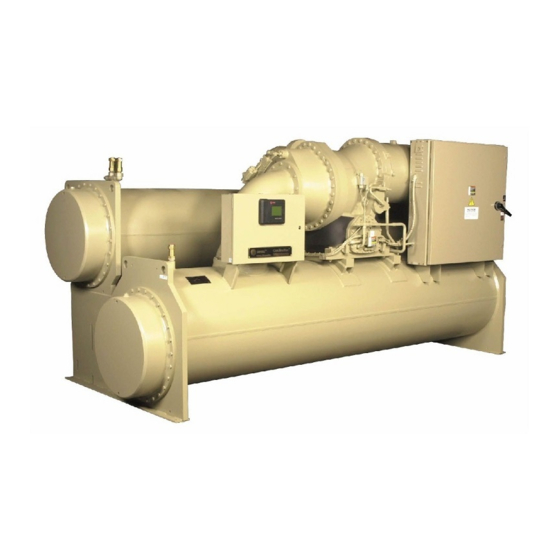
- Page 7 General Information Figure 2. General CVGF unit component Unit-Mounted Starter (Optional) Two-Stage Compressor Condenser Relief Valves Evaporator Oil Pump Control Panel AdaptiView Unit Nameplate Figure 3. Component location for typical CVGF unit (back view) Motor Unit nameplate Relief valves Oil cooler Economizer CVGF-SVX03B-EN...
- Page 8 The owner must provide reasonable evidence that the damage did not occur after de- livery. • Notify the Trane sales representative and arrange for repair. Do not repair the unit, however, until damage is inspected by the damage is inspected by the transportation...
- Page 9 Figure 2 and Figure 3 show a typical CVGF unit and its components. Water inlet and outlet openings are covered before shipment. The oil tank is factory-charged with 15 gallons (56.8L) of Trane Oil 37 and a holding charge of 5 psig (34 kPa) of dry nitrogen at 70°F (21°C).
- Page 10 General Information Model number digits are selected and assigned in accordance with the following definitions using the typical model number example shown below: CVGF0500HA0C31609005B1B5B1C2306G4A1E2CC0A0CL C = (1st digit) V = (2nd digit) Hermetic Centrifugal Compressor G = (3rd digit) Gear Drive F = (4th digit) Development sequence 0500 = (5th, 6th, 7th, and 8th digit) Nominal compressor tonnage 0400 = 400 tons...
- Page 11 General Information 674 = 674 CPKW 719 = 719 CPKW 751 = 751 CPKW 808 = 808 CPKW SSS = Special 0900 = (16th, 17th, 18th, and 19th digit) Compressor Impeller Cutback 0880 CPIM 0890 CPIM 0900 CPIM 0910 CPIM 0920 CPIM 0930 CPIM 0940 CPIM...
- Page 12 General Information B = (25th digit) Condenser Tube Bundle A = Small bundle B = Medium bundle C = Large bundle D = Extra large bundle S = Special 1 = (26th digit) Condenser Tubes 1 = .75 diameter .028 wall internally enhanced cu tube 2 = 1.00 diameter .028 wall internally enhanced cu tube 3 = .75 diameter .035 wall 90/10 cu/ni tube 4 = .75 diameter .028 wall titanium tube...
- Page 13 General Information 1 = (31st digit) Control: Operating Status 0 = None 1 = Operating Status G = (32nd digit) Control: Generic BAS 0 = None G = Generic BAS 4 = (33rd digit) Tracer Communication Interface 0 = None 4 = COMM 4 5 = COMM 5 6 = MODBUS (AdaptiView Only)
- Page 14 General Information F = 9.8 Rim diameter G = 10.4 Rim diameter H = 11.0 Rim diameter J = 11.7 Rim diameter K = 12.7 Rim diameter L = 13.5 Rim diameter M = 14.3 Rim diameter N = 15.1 Rim diameter S = Special 0 = (40th digit) Special Options 0 = None...
- Page 15 General Information Service Model Numbers –Solid State Motor Starter An example of a typical Solid State ” IT ” starter model number is: CVSR0035FAA01EA0E1 Model Number Digit Identification - Model number digits are selected and assigned in accordance with the following definitions using the model number example shown above.
- Page 16 General Information N = 80 KVAR P = 90 KVAR R = 100 KVAR T = 120 KVAR U = 125 KVAR V = 150 KVAR S = Special A = (15th Digit) Ground Fault Protection 0 = None A = Ground Fault Protection S = Special 0 = (16th digit) Special Options 0 = None...
- Page 17 General Information S = Special 0 = (12th digit) Connection Type 0 = Terminal Block 1 = Disconnect Switch - Non-Fused 2 = Circuit Breaker 3 = Circuit Breaker Current Limiting 4 = Circuit Breaker High Interrupt Cap 5 = Circuit Breaker Higher Interrupt Cap S = Special 1 = (13th digit) Agency Listing 1 = UL &...
- Page 18 General Information Installation Overview For convenience, Table 1 summarizes responsibilities that are typically associated with the CVGF chiller installation process. Table 1. Installation responsibility chart for CVGF units Requirement Trane-supplied, Trane-supplied, Field-supplied, Trane-installed Field-installed Field-installed Rigging Safety chains Clevis connectors...
- Page 19 General Information Refer to the Mechanical and Electrical sections of this manual for detailed instruc- tions. • Locate and maintain the loose parts such as, isolators, bulb wells, temperature sen- sors, flow sensors or other factoryordered field-installed options, as required. Loose parts are located in the starter panel if equipped with a unit-mounted starter.
-
Page 20: Overall Dimensions - Feet-Inch (Mm
General Information Table 2. General data: 400 and 500 ton units Nominal Tonnage 0.75 0.75 0.75 0.75 Tube Outside Diameter (inch) Evaporator Water Pass Three Three Three Three Refrigerant Type R134a R134a R134a R134a R134a R134a R134a R134a Refrigerant Charge - pounds (kg) (295) (295) - Page 21 General Information T able 2. General data: 400 and 500 ton units (continued) Nominal Tonnage Tube Outside Diameter 0.75 0.75 0.75 0.75 (inch) Three Three Three Three Evaporator Water Pass Water Volume - 150 pound Waterboxes Evaporator Water 101.7 101.49 95.7 95.4 117.2...
-
Page 22: Overall Dimensions - Feet-Inch (Mm
General Information Table 3. General data: 650 ton units Nominal Tonnage Tube Outside 0.75 Diameter (inch) Evaporator Water Pass Three Three Refrigerant Type R134a R134a R134a R134a Refrigerant Charge - pounds (kg) (442.3) (442.3) (442.3) (442.3) Oil Charge gallon (l) (56.8) (56.8) (56.8) - Page 23 General Information Table 3. General data: 650 ton units (continued) Nominal Tonnage Tube Outside 0.75 Diameter (inch) Evaporator Water Pass Three Three Water Volume - 150 pound Waterboxes 163.2 158.2 154.1 149.1 Evaporator Water Storage gallon (l) (618) (599) (583) (564) Condenser Water 185.1...
-
Page 24: Overall Dimensions - Feet-Inch (Mm
General Information Table 4. General data: 700 ton family Nominal Tonnage 0.75 0.75 0.75 0.75 Tube Outside Diameter (inch) Evaporator Water Three Three Three Three Pass Refrigerant Charge - pounds (kg) (397) (397) (397) (397) 420) (420) (420) (420) Oil charge - gallons (l) (56.8) (56.8) - Page 25 General Information Table 4. General data: 700 ton family (continued) Nominal Tonnage Tube Outside Diameter 0.75 0.75 0.75 0.75 (inch) Three Three Three Three Evaporator Water Pass Operational Data Minimum Evaporator Flow GPM (l/s) (39.4) (26.3) (35.7) (23.8) (44.5) (29.7) (39.6) (26.4) Maximum Evaporator...
-
Page 26: Overall Dimensions - Feet-Inch (Mm
General Information Table 4. General data: 700 ton family (continued) Nominal Tonnage 0.75 Tube Outside Diameter (inch) Evaporator Water Three Three Pass Refrigerant Charge (442) (442) (442) (442) - pounds (kg) Oil charge - gallons (l) (56.8) (56.8) (56.8) (56.8) Overall Dimensions - Feet-Inch (mm) Length 16'11"... - Page 27 General Information Table 4. General data: 700 ton family (continued) Nominal Tonnage Tube Outside 0.75 Diameter (inch) Three Three Evaporator Water Pass Operational Data Minimum Evaporator Flow GPM (l/s) (49.5) (33) (44) (29.3) Maximum Evaporator 2874 1916 2559 1706 Flow GPM (l/s) (181.3) (120.9) (161.4)
-
Page 28: Overall Dimensions - Feet-Inch (Mm
General Information Table 5. General data: 800 ton units Nominal Tonnage 0.75 Tube Outside Diameter (Inch) Evaporator Water Pass Three Three Refrigerant Type R134a R134a R134a R134a Refrigerant Charge- pounds (kg) (442.3) (442.3) (442.3) (442.3) Oil Charge gallon (l) (56.8) (56.8) (56.8) (56.8) - Page 29 General Information Table 5. General data: 800 ton units (continued) Nominal Tonnage Tube Outside Diameter 0.75 (inch) Three Three Evaporator Water Pass Water Volume - 150 pound Waterboxes 190.4 185.4 177.4 172.4 Evaporator Water Storage (721) (702) (672) (653) gallon (l) Condenser Water Storage 213.5 213.5...
-
Page 30: Overall Dimensions - Feet-Inch (Mm
General Information Table 6. General data: 1000 ton family Bundle Tube Outside 0.75 0.75 0.75 0.75 Diameter (inch) Evaporator Water pass Three Three Three Three Overall Dimensions - Feet-Inch (mm) Length 17' - 5 13/32" 17' - 5 13/32" 17' - 5 13/32"17' - 5 13/32" 17' - 5 13/32"... -
Page 31: Overall Dimensions - Feet-Inch (Mm
General Information Table 6. General data: 1000 ton family (continued) Bundle Tube Outside 0.75 0.75 0.75 0.75 Diameter (inch) Evaporator Water pass Three Three Three Three Overall Dimensions - Feet-Inch (mm) Length 17' - 5 13/32" 17' - 5 13/32" 17' - 5 13/32" 17' - 5 13/32" 17' - 5 13/32" 17' - 5 13/32" 17' - 5 13/32"... - Page 32 General Information Cooling Cycle The refrigeration cycle of the CVGF chiller can be described using the pressure-enthal- py diagram shown in Figure 4. Key state points are indicated and will be referred to in the following discussion. A schematic of the system showing refrigerant flow is given in Figure 5.
- Page 33 An innovative design feature of the CVGF chiller is maximizing the evaporator heat transfer performance while minimizing refrigerant charge requirements. This is accom- plished by the Trane-patented falling film evaporator design. The amount of refrigerant charge required in CVGF is less than that in comparably sized chillers of flooded evap- orator design.
- Page 34 General Information Figure 5. Refrigerant flow diagram Starter Internal filter Compressor Inlet Gears vanes High lift Motor unloading Bearings valve Condenser (HLUV) Fixed Oil cooler orifice Condenser sump Strainer Economizer Oil sump Fixed orifice Pump Fixed orifice Distributor Refrigerant Flow Evaporator CVGF-SVX03B-EN...
- Page 35 General Information Compressor Description The CVGF compressor consists of three distinct sections: the two-stage centrifugal compressor, the motor, and the gear box with integral oil sump. See Figure 6. Compressor The centrifugal compressor is two-stage with high-strength aluminum alloy fully shrouded impellers.
- Page 36 General Information Figure 6. Compressor cross-section view Motor rotor Motor shaft Discharge end Bull gear Motor Motor terminal housing Motor stator Pinion shaft Gear housing 2nd stage impeller 1st stage impeller Oil pump Suction sump CVGF-SVX03B-EN...
- Page 37 UT™ indicators visually confirm the viability of each device. Any PC that meets the system requirements may download the service interface software and Tracer AdaptiView updates. For more information on UT™ visit your local Trane Ser- vice company, or The Trane Company’s website at www.trane.com.
- Page 38 General Information Figure 7. CVGF sequence of operation overview Stopped Power Up Stopped Run Inhibit Starting Stopping Auto Fast Restart or Satisfied Setpoint Preparing to Shut Waiting to Start Down Shutting Starting Down Compressor Stop Command or Diagnostic Running Running Running - Limit CVGF-SVX03B-EN...
- Page 39 General Information Figure 8. Sequence of operation: power up *Note: The variation in AdaptiView Power Up time is depen- dent on the number of installed options. CVGF-SVX03B-EN...
- Page 40 General Information Figure 9. Sequence of operation: running Starter Status is Limit Mode Exit Limit Mode “Running” Starting Running Running Running - Limit Running Compressor Modulate IGV for Modulate IGV for Modulate IGV for LWT control Limit control LWT control CVGF-SVX03B-EN...
- Page 41 General Information Figure 10. Immediate shutdown to stopped or run inhibit Immediate shutdown non-latching diagnostic Run Inhibit Immediate shutdown latching diagnostic Stopped Panic stop Post lube complete Run Inhibit or Shutting down Shutting down Shutting down Running Stopped Post lube and evaporator pump off delay complete Close IGV (0-50 seconds)
- Page 42 General Information Figure 11. CVGF sequence of operation: satisfaction setpoint Satisfied setpoint Preparing shutdown Shutting down Shutting down Running Auto De-energize oil pump Close IGV Post lube (0-50 seconds) (1 minute) Confirm no oil pressure* Command IGV closed De-energize compressor 5 minutes after oil pump is de-energized Confirm no compressor...
- Page 43 General Information Oil Management The primary purpose of Oil Management is to ensure appropriate and sufficient lubri- cation to the bearings during compressor operation and to minimize refrigerant dilution in the oil. The Oil Management system performs safety checks and manages the operation of the Oil Pump and the Oil Heater.
- Page 44 General Information • AdaptiView displays a mode Waiting for Low Oil Differential Press. • The check is made if oil pump is off and before it is turned on. • AdaptiView allows five minutes for the differential oil pressure switch to open. •...
- Page 45 General Information Figure 12. Oil circuit diagram Starter Internal Filter Compressor Gears ST 2 ST 1 Motor Condenser High Lift Bearings Unloading Valve (HLUV) Oil Cooler Condenser Sump Strainer Economizer Oil Sump Fixed Orifice Pump Fixed Orifice Refrigerant Distributor Evaporator CVGF-SVX03B-EN...
-
Page 46: Installation: Mechanical
• At least every three months, attach a gauge to the service valve and manually check the pressure of dry nitrogen in the refrigerant circuit. If the pressure is below 5 psig (34 kPa) at 70°F (20°C), call a qualified service organization and the appropriate Trane sales office. - Page 47 Notes: Required vertical clearance above the unit is 36" (914 mm). There should be no piping or conduit located over the compressor motor. If the room configuration requires a variance to the clearance dimensions, contact your Trane sales office repre- sentative.
- Page 48 Installation: Mechanical Figure 13. Recommended operating and service clearances – Model CVGF with unit-mounted starters 36" (914 mm) Recommended clearance Height Width 18" (457 mm) Recommended clearance CL1/CL2 CL1/CL2 Length 48" (1219 mm) Recommended clearance Table 7. Dimensions for figure 13 Unit Dimensions With Unit Clearance Tube Pull Mounted Starters...
- Page 49 Installation: Mechanical Figure 14. Recommended operating and service clearances – Model CVGF without unit-mounted starters 36" (914 mm) Recommended clearance Height Width 18" (457 mm) Recommended clearance CL1/CL2 CL1/CL2 Length 36" (914 mm) Recommended clearance Table 8. Dimensions for figure 14 Unit Dimensions Without Unit Clearance Tube Pull Mounted Starters...
- Page 50 Installation: Mechanical Water Pipe Connections Table 9 applies to all CVGF chiller tonnage sizes 500, 700 and 1000. Refer to Table 9 for water pipe connection sizing information and evaporator and con- denser water pass information. All measurement are in either US or metric equiva- lents.
- Page 51 Specific isolator loading data is provided in the until submittal package. Also refer to Table 10. If necessary, contact your local Trane sales office for further information. Isolation Pads When the unit is ready for final placement, position isolation pads end-to-end under the full length of the chiller leg.
- Page 52 Installation: Mechanical The weight of the chiller will force the upper housing of each isolator down, perhaps causing it to rest on the isolator's lower housing. Figure 18 illustrates spring isolator construction. 6. Check the clearance on each isolator. If this dimension is less than 1/4" (6 mm) on any isolator, use a wrench to turn the adjusting bolt one complete revolution up- ward.
- Page 53 Installation: Mechanical Figure 17. Typical spring isolator construction CT-12 Spring Isolators (2) 1-B UNC Adjusting and Leveling Bolts 1/4" (6.3mm) Acoustical nonskid neoprene pad (top bottom) Free Height CT-7 Spring Isolators C-C Foundation Bolts 3/4" (19.0mm) 10 UNC Adjusting and leveling bolt Adjust isolator so that the upper housing clears the lower housing by at least 1/4"...
- Page 54 6090 (2762) 8991 (4078) 11500 (5216) 7225 (3277) 10340 (4690) 13545 (6144) Table 11. Selected spring isolators – CVGF 500 Isolator type Spring Color Location Trane Part Maximum Load Deflection Used and size lbm (kg) Coding inches (mm) CT-7-31 X10350664-050 7700 (3492.7)
- Page 55 Installation: Mechanical CVGF Rigging 1. Dimensions are in millimeters (mm). Figure 19. WARNING Heavy Objects! Do not use cables (chains or slings) except as shown. Each of the cables (chains or slings) used to lift the unit must be capable of supporting the entire weight of the unit. Lifting cables (chains or slings) may not be of the same length.
- Page 56 Anchor Bolt Detail Nuts should not be tight. Unit mounting pad 13 mm Leave 2 to 3 mm gap. thick (by Trane) Vibration isolator (by Trane) Anchor Hole Detail 75 mm steel pipe 4 ˘ 22 mm Evaporator diameter holes for...
- Page 57 Review mechanical room limitations and determine the safest method or methods of rigging and lifting the waterboxes. 1. Determine the type and size of chiller being serviced. Refer to Trane Nameplate lo- cated on chiller control panel. Important: This bulletin contains rigging and lifting information for Trane CVGF gear-driven centrifugal chillers built in Taicang China only.
- Page 58 Installation: Mechanical 4. Install hoist ring on to the lifting connection on the waterbox. Torque to 135 Nm (100 ft-lbs) for M20x2.5 (mm) threaded connection, and 37Nm (28 ft-lbs) for M12 x1.75 (mm) threaded connection. 5. Disconnect water pipes, if connected. 6.
- Page 59 Installation: Mechanical 9. Torque waterbox bolts. Torque bolts in a star pattern. Refer to Table 14 for torque values. Table 14. CVGF Torque Unit Bolt Size(mm) Evaporator Condenser CVGF 203Nm (150 ft-Ibs) 203Nm (150 ft-Ibs) Parts Ordering Information This Bulletin is informational only and does not authorize any parts or labor. Use the Table 15 for part ordering information.
- Page 60 Installation: Mechanical Figure 23 : Eyebolt connection (Safety hoist ring M20X2.5) Material list 1. American drill bushing (adb), M20x2.5 thread, Safety hoist ring, 29mm effective thread length, part No.24022, Rated 3000kg. Cut off bolt to an effective thread length of 22mm.
- Page 61 Installation: Mechanical Table 16. CVGF Waterbox Weights Domed Non-Marine Shell Fabricated Marine Fabricated Marine Description Waterbox,Welded Size Style Waterbox Style Waterbox Cover Flat Plate Weight Kg Lifting Weight Kg Lifting Weight Kg Lifting (Lbs) Connection (Lbs) Connection (Lbs) Connection Evaporator 150Psi (225) M12X1.75 (479)
- Page 62 Installation: Mechanical Water Pressure Drop Data Graph 1. Pressure drop for CVGF 500 Evaporators with 0.75 inch OD tubes and 2 pass waterboxes Flow (in GPM) Bundle C Bundle A Bundle B Graph 2. Pressure drop for CVGF 500 Condensers with 0.75 inch OD tubes and 2 pass waterboxes Flow (in GPM) Bundle C...
- Page 63 Installation: Mechanical Water Pressure Drop Data Graph 3. Pressure drop for CVGF 500 Evaporators with 1.0 inch OD tubes and 2 pass waterboxes Flow (in GPM) Bundle C Bundle A Bundle B Graph 4. Pressure drop for CVGF 500 Condensers with 1.0 inch OD tubes and 2 pass waterboxes Flow (in GPM) Bundle C...
- Page 64 Installation: Mechanical Water Pressure Drop Data Graph 5. Pressure drop for CVGF 700 Evaporators with 3/4 inch OD tubes and 2 pass waterboxes Flow (in GPM) Bundle C Bundle A Bundle B Graph 6. Pressure drop for CVGF 700 Condensers with 3/4 inch OD tubes and 2 pass waterboxes Flow (in GPM) Bundle A...
- Page 65 Installation: Mechanical Water Pressure Drop Data Graph 7. Pressure drop for CVGF 700 Evaporators with 3/4 inch OD tubes and 3 pass waterboxes Flow (in GPM) Bundle C Bundle A Bundle B Graph 8. Pressure drop for CVGF 700 Evaporators with 1.0 inch OD tubes and 2 pass waterboxes Flow (in GPM) Bundle A...
- Page 66 Installation: Mechanical Water Pressure Drop Data Graph 9. Pressure drop for CVGF 700 Condensers with 1.0 inch OD tubes and 2 pass waterboxes Flow (in GPM) Bundle C Bundle A Bundle B Graph 10. Pressure drop for CVGF 700 Evaporators with 1.0 inch OD tubes and 3 pass waterboxes Flow (in GPM) Bundle A...
- Page 67 Installation: Mechanical Water Pressure Drop Data Graph 11. Pressure drop for CVGF 1000 Evaporators with 3/4 inch OD tubes and 2 pass waterboxes Flow (in GPM) Bundle A Bundle B Bundle C Bundle D Graph 12. Pressure drop for CVGF 1000 Evaporators with 3/4 inch OD tubes and 3 pass waterboxes Flow (in GPM) Bundle A...
- Page 68 Installation: Mechanical Water Pressure Drop Data Graph 13. Pressure drop for CVGF 1000 Condensers with 3/4 inch OD tubes and 2 pass waterboxes Flow (in GPM) Bundle A Bundle B Bundle C Bundle D Graph 14. Pressure drop for CVGF 1000 Evaporators with 1.0 inch OD tubes and 2 pass waterboxes Flow (in GPM) Bundle A...
- Page 69 Installation: Mechanical Water Pressure Drop Data Graph 15. Pressure drop for CVGF 1000 Condensers with 1.0 inch OD tubes and 2 pass waterboxes Flow (in GPM) Bundle A Bundle D Bundle B Bundle C Graph 16. Pressure drop for CVGF 1000 Evaporators with 1.0 inch OD tubes and 3 pass waterboxes Flow (in GPM) Bundle A...
- Page 70 Installation: Mechanical Connecting Groove Pipes CAUTION Piping damage! To prevent damage to water piping, do not overtighten the connections. Note: Make sure that all piping is flushed and cleaned prior to starting the unit. CAUTION Equipment damage! To prevent equipment damage, bypass the unit if using an acidic flushing agent. Vents and Drains Install pipe plugs or ball valves, with National Pipe Thread (NPT) to water hose thread connections, in evaporator and condenser water box drain and vent connections be-...
- Page 71 Installation: Mechanical CAUTION Equipment damage! To prevent evaporator damage, do not exceed 150 psig (1035 kPa) evaporator water pressure for standard water boxes. The maximum pressure for highpressure water boxes is 300 psig (2100 kPa). To prevent tube damage by erosion, install a strainer in the evaporator water inlet piping.
- Page 72 The services of a qualified water-treatment specialist should be engaged to determine what treatment, if any, is advisable. The Trane Company warranty specifically excludes liability for corrosion, erosion, or deterioration of Trane equipment. Trane assumes no responsibility for the results of the use of untreated, improperly treated, saline, or brackish water.
- Page 73 Note: The AdaptiView provides a six-second time delay on the flow switch input be- fore shutting down the unit on a loss-of-flow diagnostic. If machine shutdowns persist, contact your local Trane representative. • Adjust the switch to open when water low falls below nominal. Refer to the General Data tables for minimum flow recommendations for specific water-pass arrange- ments.
- Page 74 Installation: Mechanical Thermal Insulation All CVGF units are available with optional factory installed thermal insulation. If the unit is not factory insulated, install insulation over the areas with designated dotted lines in Figure 25. Refer to Table 17 for types and quantities of insulation required. All CVGF units come from the factory with oil sump insulation.
- Page 75 Installation: Mechanical Figure 25. Typical CVGF insulation requirements Insulate where dotted lines are indicated. Suction line pipe Gear Housing – Front View Oil sump casing Oil sump Suction cover casing Gear Housing – Side View Oil sump casing Evaporator Evaporator water box Evaporator water box Table 17.
-
Page 76: Installation: Electrical
Installation: Electrical General Requirements WARNING Live Electrical Components! During installation, testing, servicing and troubleshooting of this product, it may be necessary to work with live electrical components. Have a qualified licensed electri- cian or other individual who has been properly trained in handling live electrical com- ponents perform these tasks. - Page 77 Installation: Electrical 3. Use copper conductors to connect the 3-phase power supply to the remote or unit- mounted starter panel. CAUTION Use Copper Conductors Only! Unit terminals are not designed to accept other types of conductors. Failure to use copper conductors may result in equipment damage. 4.
- Page 78 Installation: Electrical Optional PFCCs Power factor correction capacitors (PFCCs) are designed to provide power factor cor- rection for the compressor motor. They are available as an option. Note: Remember that the PFCC nameplate voltage rating must be greater than or equal to the compressor voltage rating stamped on the unit nameplate.
- Page 79 Installation: Electrical Figure 27. PFCC leads routed through overload current transformer Line Line PFCC PFCC Overload Overload Current Current - OR - Transformer Transformer Load Motor Load Motor Note: See the attached wiring diagram for more detail. CVGF-SVX03B-EN...
- Page 80 Installation: Electrical Interconnecting Wiring Typical equipment room conduit layouts with and without unitmounted starters are shown in Figures 28 and 29, respectively. IMPORTANT Keep in mind that the interconnecting wiring between the starter panel, compressor and UCP control panel is factoryinstalled with unit-mounted starters but must be fiel- dinstalled when a remotemounted starter is used.
- Page 81 Installation: Electrical Figure 29. Typical equipment room layout with remote-mounted Wye-Delta starter Line side power wiring Remote-mounted starter Load power wiring IPC circuit 115 Volt control conduit <30V conduit See Note 3 See Note 2 Motor terminal box Notes: 1. Refer to the unit field connection diagram for approximate UCP knockout locations. 2.
- Page 82 3. Tighten each bolt to 24 footpounds. 4. Install but do not connect the power leads between the starter and compressor mo- tor. (These connections will be completed under supervision of a qualified Trane ser- vice engineer after the prestart inspection).
- Page 83 Installation: Electrical CAUTION Damage to Starter components! To avoid damage remove debris inside the starter panel. Failure to do so may cause an electrical short that seriously damages the starter components. 1. If the starter enclosure must be cut to provide electrical access, exercise care to pre- vent debris from falling inside the enclosure.
- Page 84 Installation: Electrical Figure 30. Terminal stud, clamp and lug assembly Belleville washer Terminal lugs 3/8"* Bolt Belleville washer Motor terminal Terminal stud clamp Front View Mid Voltage RXL RATR RPIR CXL CATR CPIR CVGF-SVX03B-EN...
- Page 85 Operation Maintenance manual which can be obtained from the nearest Trane of- fice. It is recommended that the serviceman contact the local Trane office to obtain the most recent printing date of the form. The forms in the operation and maintenance manual are only current at the time of printing of the manual.
- Page 86 Installation: Electrical Figure 31-Illustrates communication control network to chiller units with Adaptiview Modem Remote PC PC Workstation Notebook PC Workstation Database Server for Workstation Multiple Sites Modem Building Control Unit Chilled Water Chilled Water Supply(CHW) Supply(CHW) and Return and Return Condenser Condenser Chilled...
-
Page 87: Base Loading Control Algorithm
Base Loading Control Algorithm Base Loading Control Algorithm This feature allows an external controller to directly modulate the capacity of the chiller. It is typically used in applications where virtually infinite sources of evaporator load and condenser capacity are available and it is desirable to control the loading of the chiller. - Page 88 Base Loading Control Algorithm Tracer Base Loading The Tracer commands the chiller to enter the base load mode by setting the base load mode request bit ON. If the chiller is not running, it will start regardless of the differen- tial to start.
- Page 89 Base Loading Control Algorithm Figure 32. Base loading with external mA input and with external voltage input Base Loading with External mA Input —— %RLA Base Loading using External Voltage Input —— %RLA Volts CVGF-SVX03B-EN...
-
Page 90: Control System Components
Control System Components Control System Components Control Panel Internally mounted devices For visual identification Internal Control Panel mounted devices are identified by their respective schematic designation number. Control panel items are marked on the inner back panel in the control panel (Figure 33). - Page 91 Control System Components Chilled and Condenser Water Flow Interlock Circuits Proof of chilled water flow for the evaporator is made by the closure of flow switch 5S1 and the closure of auxiliary contacts 5K1 on terminals 1X1-5 and 1A6- J3-1 and J3-2.
- Page 92 Control System Components Control Panel Devices Standard Devices Controls Field Connection Description Package Purpose Point Terminals 1A1 Power Supply Standard Converts 24 vac to 24 Vdc not for field use Standard High Pressure Cutout not for field use 1A4 Quad High Voltage Input Standard Relay #1...
- Page 93 Control System Components OPST Operation Status Option Relay output module 1A8 provide relay outs as shown: 1A8 Optional Quad Relay OPST Relay #1 MAR Alarm Relay, J2-1 NO, J2-2 NC, Output Status (Non-Latching) J2-3 common 1A8 Optional Quad Relay OPST Relay #2 Limit Warning Relay, J2-4 NO, J2-5 NC,...
- Page 94 Control System Components CDRP Refrigerant Pressure Output Option 1A15: Refrigerant Pressure Output can be configured at commissioning to correspond to ei- ther A) the absolute condenser pressure, or B) the differential pressure of the evapora- tor to condenser pressures. This output is located at 1A15-J2-4(+) to J2-6 (ground) The Output can source a maximum of 22 mA of current.
- Page 95 Control System Components B) Refrigerant Differential Pressure Indication Output: A 2 to 10 Vdc analog output is provided instead of the previous condenser pressure output signal. This 2 signal corresponds to a predetermined minimum and maximum pressure settings setup at commissioning of this feature. This relationship can be al- tered using Tracer TU ™...
- Page 96 Control System Components GBAS (Generic Building Automation System) GBAS (Generic Building Automation System) 1A15 Optional Dual GBAS Signal #1 Percent RLA Compressor Output J2-1 Output #1, J2-3 Ground Analog Input/output Module GBAS Signal #2 Condenser Rerigerant Pressure J2-4 Input #2, J2-6 Ground 1A15 Optional Dual Analog Input/output or Evaporator/Condenser...
- Page 97 280K ohms 14-26 AWG with a maximum of two 14 AWG Power, 24 +/- 10 percent Vdc, 20 mA maximum. Trane IPC3 protocol. J1-1 +24Vdc, J1-2 Ground, J1-3 COMM +, J1-4 COMM- 1A5, 1A8, 1A9 Quad Relay Output Status:...
- Page 98 J2: 14-26 AWG with a maximum of two 14 AWG J2-2 Input #1 to J2-3 (ground). J2-5 Input #2 to J2-6 (ground). Power, 24 +/- 10 percent Vdc, 60 mA maximum, Trane IPC3 protocol. Maximum Length to Run external Output signals Gauge...
- Page 99 Control System Components Note: If the chiller is operating in a limit mode (current limit, condenser limit, evapora- tor limit, and so forth), the limit operation has priority over all Large display™ manual modes of of operation. On each AdaptiView power-up, the inlet guide vanes are driven full closed to recali- brate the zero position (steps) of the Stepper motor vane actuator.
- Page 100 Control System Components The Large display ™ display module 1A22, receives 24 Vdc power from the IPC bus. AdaptiView and Wye-Delta Starter Control Circuits (Sequence of Oper- ation) Logic Circuits within the various modules will determine the starting, running, and stopping operation of the chiller.
- Page 101 Control System Components 11. The starter module must now confirm closure of the transition complete contact (2K2- AUX) within 2.32 to 2.38 seconds after the run relay (2A1-J6) is closed. Final- ly, the transition relay (2A1-J2) is opened de-energizing the transition contactor (2K4) and the compressor motor starting sequence is complete.
-
Page 102: Machine Protection And Adaptive Control
Machine Protection and Adaptive Control Machine Protection and Adaptive Control Momentary Power Loss (MPL) Protection Momentary power loss detects the existence of a power loss to the compressor motor and responds by initiating the disconnection of the compressor motor from the power source. - Page 103 Machine Protection and Adaptive Control Figure 37. CVGF sequence of operation: momentary power loss, (Lagre display™ and starter module remain pow Momentary Power Momentary Power Loss Cleared Loss Detected and Need to Cool Waiting to Start Shutting Down Running Enforce Power Up Delay Timer Close IGV (0-50 Seconds) Establish Condenser Water Flow (6 Second Minimum)
- Page 104 Machine Protection and Adaptive Control Current Overload Protection Motor currents are continuously monitored for over current protection and locked ro- tor protection. This protects the chiller from damage due to current overload during starting and running modes but is allowed to reach full load amps. This overload pro- tection logic is independent of the current limit.
- Page 105 Machine Protection and Adaptive Control Current Limit Protection Current Limit Protections exist to avoid motor current overload and damage to the compressor motor during starting and running. The Current Limit Setpoint (CLS) can be changed from: Front Panel, External Ana- log input (with GBAS option), or Tracer (Tracer option).
- Page 106 Machine Protection and Adaptive Control SoftLoading Softloading stabilizes the startup control during the initial chiller pulldown. Soft load- ing is used to bring the building loop temperature from its start value to the Chilled Water or Hot Water Setpoint in a controlled manner. Without soft loading, the chiller controls will load the chiller rapidly and use the full chiller capacity to bring the loop temperature to setpoint.
- Page 107 Machine Protection and Adaptive Control This limit allows the chiller to continue to run at a reduced load. Evaporator Limit uses the Evaporator Refrigerant Temperature sensor in a PID algo- rithm (similar to the Leaving Water Temperature control) that allows the chiller to run at the LRTC + 2 degree F (1.1°C).
- Page 108 Machine Protection and Adaptive Control Figure 39. Cutout strategy Chilled-Water Set Point Differential to stop adjustment range X degrees minimum differential Y degrees minimum differential Evaporator leaving-water 2°F (1.1°C) temperature cutout 2.5°F (1.36°C) 0.5°F (0.28°C) Integrate to trip Evaporator limit Limit loading Evaporator limit set point Hold...
- Page 109 Machine Protection and Adaptive Control Restart Inhibit This function provides short cycle protection for the motor, and indirectly also short cycling protection for the starter since the starter is designed to operate the motor un- der all the conditions of motor performance. Restart Inhibit Function Using Time Base This method uses straight start-to-start timer to determine when to allow the next start.
- Page 110 Machine Protection and Adaptive Control 10 minutes of compressor run. After that, if the oil temperature falls below this cutout temperature for more than 60 consecutive seconds this diagnostic is issued. Low Oil Temperature Cutout If the oil temperature is at or below the Low Oil Temperature Cutout, for more than 60 consecutive seconds this diagnostic will be issued stopping the compressor.
- Page 111 Machine Protection and Adaptive Control High Lift Unloading Valve and copper lines do not exist. The LLID (1A9) with the High Lift Unloading relay always exists. Note: There is noticeable noise, due to gas flow, when the high lift unloading valve is open.
-
Page 112: Unit Startup
Unit Startup Pre-Commissioning Bump Start Procedure Note: The following procedure is a requirement prior to the first start of the chiller. Failure to complete may result in damage to the compressor and void the warranty. Procedure Complete all control settings. 2. - Page 113 Unit Startup Unit Startup Unit Start-Up Procedures Daily Unit Start-Up Verify the chilled water pump and condenser water pump starter are in “ON” or “AUTO. ” 2. Verify the cooling tower is in “ON” or “AUTO. ” 3. Check the oil tank oil level; the level must be visible in or above the lower sight glass.
- Page 114 Unit Startup point, all air must be removed from the system (including each pass). Then close the vents in the condenser water boxes. Open all of the valves in the evaporator chilled water circuit. 5. If the evaporator was previously drained, vent and fill the evaporator and chilled water circuit.
-
Page 115: Periodic Maintenance
6. Once the unit is secured for winter, the maintenance procedures described under “Annual Maintenance” in the Periodic Maintenance section of this manual should be performed by authorized Trane service technicians. WARNING Refrigerant Discharge Hazard! DO NOT ALLOW CHILLER TO INCREASE IN TEMPERATURE OR PRESSURE WHILE THE UNIT IS OFF. -
Page 116: Periodic Maintenance
The acceptance of a warranty claim may depend on this. Annual Checks The yearly maintenance should be performed by an authorized Trane service techni- cian. It should include weekly checks. Check setting and operation of all controls and safety devices. - Page 117 Any reliable water treatment company will be able to recommend a cleaning solution for the job. Note: Trane assumes no responsibility if deterioration of the unit is due to inadequate water treatment. Evaporator cleaning The evaporator is part of a closed water circuit and should not accumulate an appre- ciable amount of scale or sludge.
- Page 118 Periodic Maintenance fore the chiller can be returned to operation. Diagnostic Codes A Latching diagnostic will shut down the machine or a part of the machine if so in- dicated. A latching diagnostic will require a manual reset to restore operation. A Non-latching diagnostic will shut down the machine or a part of the machine if so in- dicated.
- Page 119 Periodic Maintenance forth), use the following procedure for removing the oil. Removing Compressor Oil Make sure the unit is not running and the power has been disconnected to the oil heaters. To remove the compressor oil, attach an oil recovery and recharge hose or line to the oil sump drain valve located on the bottom of the oil sump (See Figure 40.
- Page 120 CVGF units ship factory charged with 15 gallons (56.8 l) of oil and a 5 psig (34 kPa) @ 70 °F (20°C) dry nitrogen holding charge. Note: The correct oil charge for all CVGF units is 15 gallons (56.8 l) of Trane OIL00037 (Trane OIL00037 is R134a miscible oil in 1-gallon (3.785 l) containers). A 5 gallon (18.9 l) container of Trane approved R134a oil is available (Trane OIL00049).
- Page 121 Periodic Maintenance pump” screen. Turn the oil pump on in manual mode and let it run for several min- utes. This will charge the oil lines and oil cooler with oil. 8. After shutting the oil pump off, check the oil level in the sump sight glasses. The level should be between the center of the upper glass and center of the lower sight glass.
- Page 122 Periodic Maintenance Remove the oil filter and o-ring. 8. Install a new oil filter, o-ring, and Roto-Lock nylon seal. 9. Replace the oil filter cover and torque the bolts and Roto-Lock connector. The cover is torqued to 19 lb-ft (2.62 N-m) and the Roto-Lock to 90 lb-ft (12.44 N-m). 10.
- Page 123 Periodic Maintenance Pump. Place oil pump in manual mode. Check the oil pressure gauge readings and calculate the differential oil pressure by subtracting the oil sump pressure reading from the discharge oil pressure reading. I f t h e d i f f e r e n t i a l pressure is between 18 to 22 psid (124¬151 kPa), the oil pressure regulating valve should not be adjusted.
- Page 124 Periodic Maintenance Hazardous Voltage! Disconnect all electric power, including remote disconnects before servicing. Follow proper lockout/tagout procedures to ensure the power can not be inadvertently en- ergized. Failure to disconnect power before servicing could result in death or serious injury. Evacuation and Dehydration Disconnect ALL power while evacuating the system.
- Page 128 March 2016 Supersedes CVGF-SVX03A-EN,CVGF-SVU02B-E4, CVGF-SVN02C-E4 www.trane.com Trane has a policy of continuous product and product data improvement and reserves the right to For more information, contact your local Trane change design and specifications without notice. office or e-mail us at service@trane.com...