Table of Contents
Advertisement
Installation, Operation,
and Maintenance
UniTrane™ Fan Coil and Force-Flo™ Cabinet Heater
200 - 1200 CFM
Models FC and FF , Low Vertical Models FCKB and FCLB
Only qualified personnel should install and service the equipment. The installation, starting up, and servicing of heating, ventilating, and air-
conditioning equipment can be hazardous and requires specific knowledge and training. Improperly installed, adjusted or altered equipment
by an unqualified person could result in death or serious injury. When working on the equipment, observe all precautions in the literature and
on the tags, stickers, and labels that are attached to the equipment.
March 2014
SAFETY WARNING
UNT-SVX07E-EN
Advertisement
Table of Contents
Troubleshooting

Related Manuals for Trane UniTrane Fan Coil


Summary of Contents for Trane UniTrane Fan Coil
- Page 1 Installation, Operation, and Maintenance UniTrane™ Fan Coil and Force-Flo™ Cabinet Heater 200 - 1200 CFM Models FC and FF , Low Vertical Models FCKB and FCLB SAFETY WARNING Only qualified personnel should install and service the equipment. The installation, starting up, and servicing of heating, ventilating, and air- conditioning equipment can be hazardous and requires specific knowledge and training.
-
Page 2: Warnings, Cautions And Notices
Hydrogen, Chlorine, Fluorine and or serious injury. Carbon (HCFCs). Not all refrigerants containing these compounds have the same potential impact to the environment. Trane advocates the responsible handling of all refrigerants-including industry replacements for CFCs such as HCFCs and HFCs. Responsible Refrigerant Practices! -
Page 3: Table Of Contents
Table of Contents Warnings, Cautions and Notices Vertical Units ..... . .48 ..2 Wall Box . - Page 4 Zone Sensor Settings Wireless Comm Interface (WCI) ....65 ..78 Address Setting ....65 Quantity of WCIs per Network .
- Page 5 ZN010 and ZN510 Operation ..103 Steam and Water Coils ....122 Sequence of Operation ... . . 103 Coil Winterization .
- Page 6 ZN010, ZN510, and ZN520 Controllers Troubleshooting Other Unit Functions .153 . . . 136 LED Activity ..... . . 136 Wiring Diagrams .
-
Page 7: Model Number Descriptions
No piping, RH, with auxiliary Following is a complete description of Rose Mauve drain pan the UniTrane fan coil and Force Flo No piping, LH, with auxiliary cabinet heater model number. Each digit Digit 16 — Tamperproof Locks/ drain pan... - Page 8 Model Number Descriptions Digit 20 — Coil Air Vent Digit 27 — Main Control Valve Digit 28 — Auxiliary Control Valve (Fan Coil only) Automatic air vent None Manual air vent 2-way, 2-position, NO (30 psig) None 3-way, 2-position, NO (28 psig) 2-way, 2-position, NO (30 psig) Digits 21, 22, 23 —...
- Page 9 Model Number Descriptions Digit 30 — Control Type Digit 35 — Control Function #3 Digit 41 — Auxiliary Autoflow (Fan Coil only) GPM (Fan Coil only) Fan mode switch Tracer ZN010 None None Tracer ZN510 Condensate overflow detection Tracer ZN520 Digit 36 —...
-
Page 10: Unitrane™ Fan Coil Low Vertical Model
Keylock access door control valve Leveling feet Following is a complete description Field-supplied analog valve Keylock access door with of the UniTrane fan coil low height (2-10VDC) leveling feet vertical model. 2-way, 2-position, NO (30 psig) Digit 16 — Main Coil Type Cv = 2.3... - Page 11 Model Number Descriptions Digit 25 — Auxiliary Control Digit 26 — Piping Packages/End Digit 31 — Control Function 2 Valve Valves Without occupant call or IAQ status Field-supplied N/O control valve Without piping Field-supplied N/C control valve Basic ball valve supply and Digit 32 —...
-
Page 12: General Information
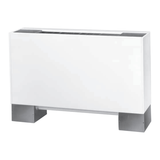
General Information UniTrane™ fan coils and Force Flo™ cabinet heaters are three-speed switch option, which ships separately, comes intended for single zone applications. These units have with a low voltage (24 volt AC) transformer. load capabilities of 200 to 1200 cfm. See Figure 1 for unit The Tracer ZN010, ZN510, ZN520, and UC400 controllers... -
Page 13: Pre-Installation
See “Receiving Checklist” Notify your Trane sales representative of the damage section for detailed instructions. and arrange for repair. Do not attempt to repair the unit without consulting the Trane representative. -
Page 14: Site Preparation
Pre-Installation If indoor storage is not possible, Trane makes the • Confirm the floor or foundation is level. For proper unit following recommendations to prevent damage: operation, the unit must be level (zero tolerance) in both horizontal axis. Note: Keep the equipment on the original wooden blocks/ skid for protection and ease of handling. -
Page 15: Dimensions And Weights
Dimensions and Weights Service Clearances allow access into the unit. See Figure 2 Figure 3 recommended service and operating clearances. Service access is available from the front on vertical units and from the bottom on horizontal units. Cabinet and recessed units have removable front or bottom panels to Figure 2. -
Page 16: Component Data
Dimensions and Weights Component Data Table 1. Fan coil and cabinet heater component data Unit Size Coil Data Face Area (ft 0.80 0.80 1.10 1.60 2.10 3.20 3.20 L x D x H (in.) 2-Row 15 x 1.7 x 8 15 x 1.7 x 8 20 x 1.7 x 8 29.5 x 1.7 x 8... -
Page 17: Available Models
Dimensions and Weights Available Models Figure 4. Available UniTrane fan coils and Force Flo cabinet heaters Model A: Model B: Model C: Model D: Vertical Concealed Vertical Cabinet Horizontal Concealed Horizontal Cabinet Model E: Model F: Model H: Model J: Horizontal Recessed Wall Hung Cabinet Vertical Recessed... -
Page 18: Model A Vertical Concealed
Dimensions and Weights Model A Vertical Concealed Figure 5. Model A Vertical Concealed Top View Power wiring 1 3/32 in. KO bottom 7/8 in. KO 1 3/4 in. 1 3/4 in. only Auxiliary 3 3/8 in. control 6 1/4 in. box opt. - Page 19 Dimensions and Weights Table 3. Model A Vertical concealed unit dimensions (inches) Unit Size 200-300 1000-1200 No. Fans No. Motors 32 11/16 37 11/16 47 3/16 55 11/16 74 11/16 21 5/16 26 5/16 35 13/16 44 5/16 63 5/16 22 13/16 27 13/16 37 5/16...
-
Page 20: Model B Vertical Cabinet
Dimensions and Weights Model B Vertical Cabinet Figure 6. Model B vertical cabinet Top View (4) 5/8 in dia keyslot hanger holes 6 5/8 in. 2 7/8 in. 6 5/8 in. 1 in. (4) Unit leveling devices 1 3/8 in. (optional) 6 1/4 in. -
Page 21: Unit Size
Dimensions and Weights Table 4. Model B Vertical cabinet unit dimensions (inches) Unit Size 200-300 1000-1200 No. Fans No. Motors 33 5/16 38 5/16 47 13/16 56 5/16 75 5/16 21 5/16 26 5/16 35 13/16 44 5/16 63 5/16 7 5/8 7 1/8 8 7/8... -
Page 22: Model C Horizontal Concealed
Dimensions and Weights Model C Horizontal Concealed Figure 7. Model C Horizontal concealed unit 2 5/16 in. Top View 2 5/16 in. Back inlet duct collar 3 1/4 in. 9/16 in. 9/16 in. (4) 5/8 in. dia keyslot hanger holes Optional Secondary drain connection disconnect... -
Page 23: Locations. All Duct Collar Dimensions Are To The Outside Of The Collar
Dimensions and Weights Table 5. Model C Horizontal concealed unit dimensions (inches) Unit Size 200-300 1000-1200 No. Fans No.Motors 32 11/16 37 11/16 47 3/16 55 11/16 74 11/16 21 5/16 26 5/16 35 13/16 44 5/16 63 5/16 22 13/16 27 13/16 37 5/16 45 13/16... -
Page 24: Model D Horizontal Cabinet
Dimensions and Weights Model D Horizontal Cabinet Figure 8. Model D Horizontal Cabinet Top View 8 in. 8 in. Back inlet duct collar (4) 5/8 in. dia keyslot Back and bottom hanger holes inlet louvers Secondary drain connection for Optional 3/8 in. - Page 25 Dimensions and Weights Table 6. Model D Horizontal cabinet dimensions (inches) Unit Size 200-300 1000-1200 No. of Fans No. of Motors 33 5/16 38 5/16 47 3/16 56 5/16 75 5/16 21 5/16 26 5/16 35 13/16 44 5/16 63 5/16 7 5/8 7 1/8 8 7/8...
-
Page 26: Model E Horizontal Recessed
Dimensions and Weights Model E Horizontal Recessed Figure 9. Model E Horizontal Recessed Top View 8 13/16 in. 8 13/16 in. Back inlet duct collar 1 1/2 in. 3/4 in. (4) 5/8 in. dia keyslot hanger holes Bottom inlet louvers Optional Secondary drain disconnect... - Page 27 Dimensions and Weights Table 7. Model E Horizontal recessed unit dimensions (inches) Unit Size 200-300 1000-1200 No. Fans No. Motors 35 13/16 40 13/16 50 5/16 58 13/16 77 13/16 21 5/16 26 5/16 35 13/16 44 5/16 63 5/16 22 13/16 27 13/16 37 5/16...
-
Page 28: Model F Vertical Wall Hung Cabinet
Dimensions and Weights Model F Vertical Wall Hung Cabinet Force Flo Units Only Figure 10. Model F Vertical Wall Hung Cabinet (Force Flo only) 2 7/8 in. Top View 1 3/8 in. 6 1/4 in. Power 7/8 in. KO wiring Top outlet quadrifuser Unit control 1 3/32 in. - Page 29 Dimensions and Weights Table 8. Model F Vertical wall hung cabinet unit dimensions (inches) Unit Size 200-300 1000-1200 No. Fans No. Motors 33 5/16 38 5/16 47 13/16 56 5/16 75 5/16 21 5/16 26 5/16 35 13/16 44 5/16 63 5/16 7 5/8 7 1/8...
-
Page 30: Model H Vertical Recessed
Dimensions and Weights Model H Vertical Recessed Figure 11. Model H Vertical Recessed Top View 1 3/4 in. 1 3/4 in. (4) 5/8 in. dia keyslot 5 1/2 in. hanger holes 3 7/16 in. 6 5/8 in. 5 5/16 in. Power wiring 7/8 in. - Page 31 Dimensions and Weights Table 9. Model H Vertical Recessed Unit Unit Size 200-300 1000-1200 No. Fans No. Motors 32 11/16 37 11/16 47 3/16 55 11/16 74 11/16 21 5/16 26 5/16 35 13/16 44 5/16 63 5/16 22 13/16 27 13/16 37 5/16 45 13/16...
-
Page 32: Model J Vertical Slope Top Cabinet
Dimensions and Weights Model J Vertical Slope Top Cabinet Figure 12. Model J Vertical Slope Top Top View 2 7/8 in. 6 5/8 in. 6 5/8 in. (4) Unit leveling devices 1 3/8 in. 1 1/16 in. (optional) 6 1/4 in. 6 1/2 in. - Page 33 Dimensions and Weights Table 10. Model J Vertical slope top cabinet unit dimensions Unit Size 200-300 1000-1200 No. Fans No. Motors 33 5/16 38 5/16 47 13/16 56 5/16 75 5/16 21 5/16 26 5/16 35 13/16 44 5/16 63 5/16 7 5/8 7 1/8 8 7/8...
-
Page 34: Model K Low Vertical Concealed
Dimensions and Weights Model K Low Vertical Concealed Figure 13. Model K Low Vertical Concealed (2) 5/8 in. dia keyslot Top View hanger holes (2) 7/8 in. KO Power wiring bottom only 2 3/8 in. 6 1/4 in. 12 1/4 in. Top outlet 12 1/2 in. - Page 35 Dimensions and Weights Table 11. Model K Low vertical concealed unit dimensions (in.) and weights (lb) Unit Size 41-7/16 50-15/16 59-7/16 26-1/4 35-3/4 44-1/4 27-15/16 36-13/16” 45-15/16 22-5/16 31-13/16 40-5/16 24-1/4 33-3/4 42-1/4 Operating Weight Shipping Weight Coil connections are always on the drain pan side and opposite the control box. Coil connections are 5/8-in. O.D. sweat. See page 43 Notes: locations.
-
Page 36: Model L Low Vertical Cabinet
Dimensions and Weights Model L Low Vertical Cabinet Figure 14. Model L Low vertical cabinet (2) 5/8 in. dia keyslot hanger holes (2) 1 3/32 in. KOs Top View control wiring 10 15/16 in. 10 15/16 in. 3 1/16 in. (4) Unit leveling devices bottom only (optional) - Page 37 Dimensions and Weights Table 12. Model K Low vertical cabinet unit dimensions (in.) and weights (lb) Unit Size 46 15/16 56 7/16 64 15/16 26 1/4 35 3/4 44 1/4 11 7/16 13 5/16 11 7/16 24 1/4 33 3/4 42 1/4 Operating Weight Shipping Weight...
-
Page 38: Model M Inverted Vertical Cabinet
Dimensions and Weights Model M Inverted Vertical Cabinet Force-Flo Unit Only Top View 4 9/16 in. 2 5/16 in. 6 5/8 in. 7/8 in. Power wiring Top outlet quadrifuser Unit control 1 3/32 in. bottom or bar grille only 6 in. 6 in. - Page 39 Dimensions and Weights Table 13. Model M Inverted vertical cabinet unit dimensions (in.) and weights (lb) Unit Size 02–03 10–12 33 5/16 38 5/16 47 13/16 56 5/16 75 5/16 21 5/16 26 5/16 35 13/16 44 5/16 63 5/16 7 5/8 7 1/8 8 7/8...
-
Page 40: Model N Inverted Vertical Recessed
Dimensions and Weights Model N Inverted Vertical Recessed Force-Flo Unit Only Top View 1 3/4 in. 1 3/4 in. 5 1/2 in. (4) 5/8 in. dia keyslot hanger holes 6 5/8 in. Power 7/8 in. KO wiring 1 3/32 in. bottom only 2 5/16 in. - Page 41 Dimensions and Weights Table 14. Model N Inverted vertical recessed unit dimensions (in.) and weights (lb) Unit Size 02–03 10–12 27 7/8 32 7/8 42 3/8 50 7/8 69 7/8 21 5/16 26 5/16 35 13/16 44 5/16 63 5/16 22 13/16 27 13/16 37 5/16...
-
Page 42: Mode P Compact Concealed
Dimensions and Weights Mode P Compact Concealed Figure 15. Model P Compact Concealed Top View 2 5/16 in. 2 5/16 in. Back inlet duct collar 3 1/4 in. 9/16 in. 9/16 in. (4) 5/8 in. dia keyslot Optional hanger holes discoonect Secondary drain switch... -
Page 43: Coil Connections
Dimensions and Weights Table 15. Compact concealed unit dimensions (in.) Unit Size 200-300 1000-1200 32 11/16 37 11/16 47 3/16 55 11/16 74 11/16 21 5/16 26 5/16 35 13/16 44 5/16 63 5/16 22 13/16 27 13/16 37 5/16 45 13/16 64 13/16 19 3/8... -
Page 44: Fan Coil Horizontal Units
Dimensions and Weights Fan Coil Horizontal Units Figure 17. Coil connections for fan coil horizontal units 1 in. Horizontal Concealed Horizontal Recessed (Recess panel not shown) 7/16 in. 22 3/8 in. CS 21 3/8 in. CR 21 1/16 in. HR Dimensions are typical 19 5/16 in. -
Page 45: Force Flo Vertical Units
Dimensions and Weights Force Flo Vertical Units Figure 18. Coil connections for Force Flo cabinet heater vertical units 5 3/8 in. HS 5 5/16 in. HS 5 5/16 in. HS 4 7/16 in. HR 5 5/16 in. HS 4 3/8 in. HR 4 3/8 in. -
Page 46: Force Flo Horizontal And Inverted Units
Dimensions and Weights Force Flo Horizontal and Inverted Units Figure 19. Coil connections for Force Flo cabinet heater horizontal units and inverted vertical units Inverted Vertical Cabinet Horizontal Concealed 1 in. Horizontal Recessed (recess panel not shown) 4 3/8 in. 5 5/16 in. -
Page 47: Fresh Air Opening Locations
Dimensions and Weights Fresh Air Opening Locations Horizontal Units Figure 20. Fresh air openings for horizontal units (models C, D, E, and P (back duct collar only) Outside air opening - back Horizontal Concealed 11/16 in. 3 in. and Recessed 1 5/8 in. -
Page 48: Vertical Units
Dimensions and Weights Vertical Units Figure 21. Fresh air openings for vertical units (models A, B, F, H, J, K, L, M, and N Vertical Concealed and Recessed 1 5/8 in. 1 5/8 in. Outside air opening - back Keyslot hanger holes 3 in. -
Page 49: Wall Box
Dimensions and Weights Wall Box Figure 22. Wall box Continuous mortar ribs top and bottom 1/8 in. 1/8 in. 1/2 in. 3/4 in. 1/2 in. 1 3/8 in. 1/8 in. 4 in. Woven aluminum Clearance for insect screen drainage 5/8 in. Additional internal Continuous drip lip supports equally spaced... -
Page 50: Projection Panel
Dimensions and Weights Projection Panel Figure 23. Projection panel Unit chasis end panel Projection panel Finished wall 7/8 in. 2 in. min. 6 in. max. Front View ISO Rear view ISO Table 19. Projection panel dimensions (inches) Unit Size 02–03 10–12 65 1/2 89 1/2... -
Page 51: Installation-Mechanical
For variable frequency drives 13. Ensure the low temperature detection device or other energy storing components provided by Trane option is correctly installed. or others, refer to the appropriate manufacturer’s literature for allowable waiting periods for discharge of ... -
Page 52: Installing The Unit
Installation—Mechanical Installing the Unit while holding the panel close as possible to the cabinet. While the bottom tabs are engaged, slide the front panel upward enough to allow the top engaging edge of the front Follow the procedures below to install the unit properly. panel to lap over the engaging edge of the unit. -
Page 53: Cabinet Units
Installation—Mechanical Cabinet Units Figure 24. Installing the trim ring assembly on horizontal recessed units Install the bottom panel by placing the hinged end on the unit’s hinged end (always at the return end of the unit). Refer to “Dimensions and Weights, ” page 12 for keyslot Horizontal recessed unit... -
Page 54: Duct Connections
For variable frequency drives • When making duct turns and transitions avoid sharp or other energy storing components provided by Trane turns and use proportional splits, turning vanes, and or others, refer to the appropriate manufacturer’s air scoops when necessary. -
Page 55: Coil Piping And Connections
Coil Piping and Connections Factory-Installed Piping Packages Figure 25. Piping package arrangements Auto Circuit Setter (C) This figure shows piping package components and basic arrangement. It is not an accurate pictorial of what factory- installed piping packages look like. UNT-SVX07E-EN... -
Page 56: Hydronic Coil Piping
Coil Piping and Connections Hydronic Coil Piping • All piping connections are 5/8-inch O.D. (1/2-inch nominal) female copper connections. Before installing field piping to the coil, consider the • The fan-coil supply and return piping should not following: interfere with the auxiliary drain pan or condensate line. -
Page 57: Condensate Overflow Detection Device
Coil Piping and Connections Automatic Changeover Sensor flexible plastic tube over the nipple and secure with a field supplied hose clamp. Two-pipe changeover units with either the Tracer ZN010, Note: The installer is responsible for adequately ZN510, ZN520, and UC400 and CSTI controls have an insulating field piping. -
Page 58: Venting The Hydronic Coil
Insulate and vapor seal surfaces colder than surrounding air dew-point a to prevent unplanned condensation. Trane The coil air vent is on the piping side, above the coil recommends field-insulation of the following areas to connections on the unit. - Page 59 Coil Piping and Connections Adjust the balancing fitting to obtain the same pressure Figure 34. Automatic circuit setter valve drop across the circuit setter valve as in step two when the control valve was open to the coil. Figure 35. Manual circuit setter valve, differential pressure vs.
- Page 60 This provides sufficient hydrostatic head pressure to overcome trap losses and ensure complete condensate removal. 12 in. min. b. Trane recommends using flat and thermostatic traps because of gravity drain and continuous Full size of discharge operation. steam trap c.
-
Page 61: Installation - Zone Sensors
Installation - Zone Sensors Zone Sensor Options Figure 40. Digit 30 = E and Digit 31 = X Split-mounted zone sensor, unit-mounted Control sensor options include both unit-mounted fan mode and wall-mounted setpoint dial (factory-installed) and wall-mounted sensors. Tracer™ controller options available for the zone sensors are: •... -
Page 62: Installation Considerations
Installation - Zone Sensors Figure 43. Digit 30 = F, G, J or K and Digit 31 = Y Figure 46. Digit 30 = F, G, J or K and Digit 31 = 6 Split-mounted zone sensor, unit-mounted Wall-mounted wireless temperature sensor fan mode and wall-mounted setpoint dial (WZS) (setpoint adjustment, no fan speed adjustment) and unit-mounted receiver... -
Page 63: Placement
Installation - Zone Sensors Placement Figure 48. Wall-mounted wired and wireless zone sensor dimensions Placement of the sensor is critical to proper operation (the receiver is factory-mounted on fan coil units). For most installations, barriers limit proper radio signal strength Typ R.07 in. -
Page 64: Wired Zone Sensor
Installation - Zone Sensors 4. Follow the instructions given in “Interconnection Wiring, ” page 79 and route the wires as shown in the Figure 49. Mounting sensor base plate wiring diagram. Refer to the typical wiring diagram or to the unit specific diagram on the unit. 5. -
Page 65: Receivers
Installation - Zone Sensors a. Hold the back plate against the mounting surface and mark the screw locations. Figure 52. Set address before removing insulation strip from the sensor. b. Secure the back plate against the mounting surface using included hardware. 4. -
Page 66: Observing Receiver For Readiness
Installation - Zone Sensors Figure 53. Set the rotary address switches on the Figure 54. Receiver conducts 20 second channel scan receiver Receiver Sec. LESS WIRELESS INSTALL TALL TA A LED4 LED1 LED2 LED3 SIGNAL LED5 ADDRESS POWER HEATING SET FAN/SYSTEM SETPOINT ZONE... -
Page 67: Associating Sensor To Receiver
Installation - Zone Sensors Associating Sensor to Receiver Note: The LEDs will turn Off after 5 seconds to conserve battery strength. To associate the sensor to the receiver: Figure 57. Wireless Zone Sensor (WZS) with LED lights 1. Remove the sensor cover by firmly pressing the thumb to test for battery strength tab at the bottom of the cover and pulling the cover away from the back plate. -
Page 68: Sensor Operations
Installation - Zone Sensors Sensor Operations • LED3 flashes On every 2 seconds when it is ready to accept a sensor association request. When an association request is made by a sensor, the receiver Temporary Occupancy (Timed Override) instructs the sensor on which power level to operate. Temporary occupancy (timed override) is available on Then the receiver and sensor begin operation at the model WDS. -
Page 69: Wireless Sensor Specifications
Installation - Zone Sensors Wireless Sensor Specifications Table 23. Wireless sensor specifications Component Type Sensor operating temperature 32°F to 122°F Receiver operating temperature -40°F to 158°F Storage temperature -40°F to 185°F Storage and operating humidity range 5% to 95%, non-condensing Accuracy 0.5°F over a range of 55ºF to 85°F Resolution... -
Page 70: Wireless Display Sensor (Wds)
Installation - Zone Sensors Wireless Display Sensor (WDS) Figure 60. Wrench is shown in configuration mode Configuration Procedure Note: Sensors shipped with the fan coil are pre- configured for three speeds. The configuration of the sensor determines which system features can be accessed and changes can be made by the tenant (for example, changes to cooling/heating mode, setpoint, or fan speed. -
Page 71: Displaying Setpoint Or Temperature
Installation - Zone Sensors Table 25. Configuration options for wireless display sensors Setting Configuration Options Temperature • Choose Fahrenheit or Celsius • Choose the degree resolution (whole degrees, half degrees, or tenths of degrees). Setpoint Single setpoint setpoint System No system options enabled Auto/Off Auto/Off/... -
Page 72: Locking Or Unlocking Settings
Installation - Zone Sensors Locking or Unlocking Settings Figure 64. Wireless display sensor (model WDS) in operating mode You can lock or unlock the setpoint, system, or fan setting to prevent changes. To lock or unlock a setting: 1. Verify that the sensor is in operating mode and at the home screen. -
Page 73: Changing Heating/Cooling Settings
Replace batteries. Flashing symbol indicates that approximately 14 days of operation remain. Press the Test button to display the battery status symbols. Use only UL-listed non-rechargeable 1.5 V lithium AA batteries (Trane p/n X13770035010 or equivalent). UNT-SVX07E-EN... -
Page 74: Installation - Controllers
® Trace ZN510 and ZN520 controllers are LonTalk devices because the unit will assume different ground that interface with the Trane Tracer Summit building potentials. management system. Reference the unit wiring diagram • Do not run power in the same conduit or wire bundle or submittals. -
Page 75: Tracer Uc400 Controller
Installation - Controllers Tracer UC400 Controller Setting the Address The rotary address dials on the UC400 controller serve one This section provides information about wiring the UC400 or two purposes depending upon the network: they are controller. always used for the MAC Address, which is sometimes all Note: For more detailed information, refer to: or part of the BACnet Device ID (See Figure... -
Page 76: Power Supply
SERVI SERVICE TOOL SERVICE TOOL A 24Vac power supply must be used for proper operation Trane BACnet terminator of the binary inputs, which requires 24Vac detection. In addition, the spare 24Vac outputs may be used to power relays and TRIACS. -
Page 77: Wiring Requirements
Installation - Controllers • AC transformer requirements: UL listed, Class 2 power 2. Connect the 24Vac secondary wires from the transformer, 24Vac ±15%, device max load 24VA. The transformer to the 24Vac and terminals on the transformer must be sized to provide adequate power UC400 controller (refer to the illustration below). -
Page 78: Wireless Comm Interface (Wci)
Output power: North America: 100 mW Quantity of WCIs per Network Radio frequency: 2.4 GHz (IEEE Std 802.15.4-2003 Each Trane wireless network can have a total of 31 WCIs compliant) (2405–2480 MHz, 5 MHz spacing) (30 member WCIs plus one coordinator WCI). Each... -
Page 79: Installation - Electrical
Unit transformer IT1 provides power to fan-coil unit inadvertently energized. For variable frequency drives only. Field connections directly to the transformer IT1 or other energy storing components provided by Trane may create immediate or premature unit component or others, refer to the appropriate manufacturer’s failure. - Page 80 Installation - Electrical Refer to Table 26 for the wire size range and maximum Table 29. High static ECMs programmed to reduced FLA wiring distance for each device. mode 115 Volt 208–230 Volt 277 Volt Table 26. Maximum wiring distances for low voltage Unit controls (ft) Size...
-
Page 81: Mca And Mop Calculations
Installation - Electrical Table 33. Electric heat kW, low vertical fan-coil Table 35. Force-Flo single stage, low kW electric heat Unit amps amps amps Unit Size Unit Voltage Size Voltage Wires 1.00 1.50 2.00 208/60/1 240/60/1 1.00 1.50 2.00 2.50 277/60/1 1.00 1.50... - Page 82 Installation - Electrical Table 36. Force-Flo two-stage electric heat Unit Stage Total Total Size Voltage # Wires amps/ph 208/60/1 10.9 240/60/1 12.5 277/60/1 10.9 208/60/3 240/60/3 480/60/3 208/60/1 21.7 240/60/1 25.0 277/60/1 21.7 208/60/3 12.6 240/60/3 14.5 480/60/3 208/60/1 27.5 240/60/1 31.3 277/60/1...
-
Page 83: Ecm Overview And Setup
• The ECM has integrated electronics, overload Figure 71. UniTrane fan-coil with Trane ECM motor protection and short circuit protection. The motor contains no user-serviceable components inside. NOTICE: Equipment Damage! -
Page 84: Velocitach Motor Control Board
ECM Overview and Setup VelociTach Motor Control Board • Incorporates various safety and lockout features, such as maintaining proper fan speeds if electric heat is called for. Figure 73. VelociTach motor control board Status Display Figure 74. Status display Display and Menu/Enter, Increase, and Decrease The motor control board contains a four-digit, seven- buttons... -
Page 85: Manual Fan Speed Switch (Fss)
• Fan speed switches The manual fan mode switch is available for fan-coil units that do not have Trane factory-mounted control packages. This four-position switch (off, high, medium, low) allows manual fan mode selection and is available wall mounted. The wall-mounted option is low-voltage using a factory- wired transformer. -
Page 86: Customer Supplied Thermostat Interface
ECM Overview and Setup Customer Supplied Thermostat Interface Figure 76. CSTI adapter board and field connections VSP 10V (TB4) 3 2 1 13 12 11 10 9 8 7 6 5 4 3 2 1 VSP 0–10V (TB4) VSP DC COM (TB4) Customer low-voltage 24 VAC B (hot) (TB3) interface for fan speeds,... -
Page 87: Safety Requirements
Technicians, in order to protect themselves from Note: Normally, Trane ECMs are configured for soft potential electrical, mechanical, and chemical hazards, ramps and transitions between speeds. However, MUST follow precautions in this manual and on the... -
Page 88: Velocitach Motor Control Board
If it is not practical to stay clear of these areas during adjustment of the motor control board, please contact Trane Global Parts for configuration kit that allows easy powering of the motor control board outside of the unit with a 9V battery. -
Page 89: User Interface
ECM Overview and Setup Figure 78. Operational Status Codes RPM Mode Indicates the current rpm of Motor 1 in the system. “0” rpm → here indicate that no fan speed has been requested. RUNNING/ FAN STATUS CONTINUOUS LOOP Indicates the current rpm of Motor 2 in the system. - Page 90 ECM Overview and Setup Table 39. Button actuation levels Menu/Set Button Duration Action Short Press in <1 sec None Status Display Short Press in Configuration Display Toggles between parameter name and value without saving (abandons value if changed). Long Press/Hold >3 sec Enters the configuration menu in Status Display...
-
Page 91: Priority/Error Display
ECM Overview and Setup Priority/Error Display Example 3. We wish to double check to see if the value of “820 rpm” has been saved. Under special conditions, the status display will interrupt Note: If the display has timed out and returned to the briefly to prioritize display of events: status loop, repeat Example 1 and Example 2 to Notes:... -
Page 92: Adjustments
ECM Overview and Setup Table 40. Error Codes Displayed during Indicates a locked rotor condition of Motor 1. The motor will be locked out abnormal operation. until the cause has been resolved, and the power cycled; refer to “ , ” page 148 ... - Page 93 The motor control board is factory configured to drive the board, please contact Trane Global Parts for unit to a minimum speed (catalogue “low speed” value), configuration kit that allows easy powering of the ...
- Page 94 If it is not practical to stay clear of these areas during adjustment of the motor control board, please contact Trane Global Parts for configuration kit that allows easy powering of the motor control board outside of the unit with a 9V battery.
-
Page 95: Csti Adapter Board Configuration
ECM Overview and Setup Adjusting Optional Auto-Changeover Function Generally, this will perform the same as the parameter but in addition, will disable heating on CSTI Units function on electric heat and on the changeover coil if there are fan failures. The auxillary heating coil function will continue to operate and WARNING respond to the customer heating request. - Page 96 A 10K NTC thermistor (similar to Trane part number that do not have the configurability to adapt to the X13790374010) is wired properly to the motor customer choice of valves.
-
Page 97: Velocitach Control Board Configuration
The motor control board configuration label is a. A 10K NTC thermistor (similar to Trane part number affixed to the low-voltage access lid on the outside of the X13790374010) is wired properly to the motor control panel (see Figure 77, p. -
Page 98: Motor Control Board Settings
If it is not practical to stay clear of these areas during adjustment of the motor control board, please contact Trane Global Parts for configuration kit that allows easy powering of the motor control board outside of the unit with a 9V battery. - Page 99 ECM Overview and Setup Table 42. Configuration settings of the motor control board for fan coil and cabinet heater units Note: These notes are provided for reference only, User Typical User and the motor control board label must be Description on Interface Interface used as the ultimate guide for setting up an...
- Page 100 ECM Overview and Setup Table 42. Configuration settings of the motor control board for fan coil and cabinet heater units Note: These notes are provided for reference only, User Typical User and the motor control board label must be Description on Interface Interface used as the ultimate guide for setting up an...
-
Page 101: Fan Speed Response Verification
ECM Overview and Setup Table 42. Configuration settings of the motor control board for fan coil and cabinet heater units Note: These notes are provided for reference only, User Typical User and the motor control board label must be Description on Interface Interface used as the ultimate guide for setting up an... -
Page 102: Startup
For variable frequency drives coils could result in scaling, erosion, corrosion, algae or or other energy storing components provided by Trane slime. It is recommended that the services of a qualified or others, refer to the appropriate manufacturer’s... -
Page 103: Unit Startup
Startup Unit Startup Auto (Fan Cycling) - Fan and fresh air damper cycle with control valve option to maintain setpoint temperature. In cooling mode, the fan cycles from off to medium and in Tracer ZN010 and ZN510 heating mode it cycles from off to low. When no heating or cooling is required, the fan is off and the fresh air damper Controllers option closes. -
Page 104: Binary Inputs
Startup Binary Inputs Both Tracer ZN010 and ZN510 accept a maximum of five analog inputs. See Table BIP1: Low Temperature Detection Option Table 46. Analog inputs The factory hard wires the low temperature detection Analog sensor to binary input #1 (BIP1). The sensor defaults Input Description Application... -
Page 105: Tracer Zn520 Controllers
The fan runs continuous when placed in the high, medium, LonTalk Communication. or low position. Use Rover, Trane’s installation and service tool, to change auto defaults. ZN520 Stand-Alone Operation During the transition from off to any fan speed but high,... -
Page 106: Sequence Of Operation
On button on controller attempts to maintain the space temperature at the Trane zone sensor. the stored unoccupied heating or cooling setpoint, based When the controller is in unoccupied mode, you can press... -
Page 107: Cooling Operation
Startup the controller is determined by using time-of-day The controller operates the supply fan continuously when scheduling of the building automation system. The result the controller is in the occupied and occupied standby of the time-of-day schedule can then be communicated to modes, for either heating or cooling. -
Page 108: Fan Mode Operation
Startup modulating outputs open further and binary outputs are Table Table 51, and Table energized longer. At 100 percent capacity, the heating Table 50. Local fan switch enabled valve is fully open (3-wire modulating valves) or on Communicated Fan Speed Fan Switch continuously (two-position valves). -
Page 109: Electric Heat Operation
Startup Fan Cycling Operation the entering water temperature against the effective space temperature for a maximum of three minutes. Tracer ZN520 does not support fan cycling in The controller automatically disables the entering water occupied mode. The fan cycles between high speed and temperature sampling and closes the main hydronic valve off in the unoccupied mode only. -
Page 110: Dehumidification
Startup economizing and moves the outdoor air damper back to its For more information on setup, refer to: predetermined minimum position based on the current EMTX-SVX01G-EN Rover Service Tool Installation, occupancy mode or communicated minimum damper Operation, and Programming manual. position. - Page 111 Startup Binary Outputs Table 56. Analog inputs (Tracer ZN520) Binary outputs are configured to support the following Function Range Description Terminals (see Table 55): Space Zone TB3-1 5°F to 122°F temperature input • Three fan stages (when one or two fan stages are Ground TB3-2 Analog ground...
-
Page 112: Zone Sensor
The hard- Space Temperature Measurement wired setpoint is used with the controller’s occupancy Trane zone sensors use a 10kΩ thermistor to measure the mode (occupied, occupied standby, or unoccupied), the space temperature. Typically, zone sensors are wall-... -
Page 113: Tracer Uc400 Controller
• Cooling setpoint low limit controllers and a building automation system. Communication also is possible via Rover, Trane’s service These setpoint limits only apply to the occupied and tool. Peer-to-peer communication across controllers is occupied standby heating and cooling setpoints. These... -
Page 114: Uc400 Operation
• Select the correct temperature setpoint. input BI1. Note: Select and enable zone sensor temperature • A timed override request from a Trane zone sensor (see settings to prevent freeze damage to unit. “Timed Override Control, ” page 115). •... -
Page 115: Timed Override Control
In this mode, the active space mode and remains in this mode until either the CANCEL temperature setpoint is used as the discharge air button is pressed on the Trane zone sensor or the occupied temperature setpoint. bypass time expires. -
Page 116: Discharge Air Tempering
Startup Discharge Air Tempering greater than 5°F (2.8°C) below a valid zone temperature value for hydronic cooling, the sampling function is If the controller is in cooling mode, cascade zone control enabled. When the sampling function is enabled, the initiates a discharge air tempering function when: controller opens the main hydronic valve to allow the water temperature to stabilize. -
Page 117: Exhaust Control
Startup Note: The supply fan speed source can be configured for • The exhaust fan energizes when the fan is running and BAS, local, or default value control using the Tracer when the outdoor air damper position is greater than TU service tool. -
Page 118: Modulating Outdoor/Return Air Damper
Startup 4-pipe applications supports cooling or heat/cool The minimum position for an outdoor air damper is changeover with a main valve/coil and heating only with configurable using the Tracer TU service tool for both an auxiliary valve/coil. occupied mode and occupied standby mode and for low- speed fan operation. -
Page 119: Electric Heat Operation
The controller continues to dehumidify until the sensed the status of the fan for belt-driven or direct-driven units humidity falls below the setpoint minus the relative (except Trane Macon factory ECM fan motor units). The fan humidity offset. status switch provides feedback to the controller as... - Page 120 Startup Freeze Protection (Discharge Air Temperature temporarily overriding the Reset Diagnostic Request on the Tracer TU Binary Status page. Low Limit) Note: In the ECM fan application, the VelociTach board The controller monitors the discharge air temperature will monitor the status of the fan. In case of a with a 10 kΩ...
-
Page 121: Routine Maintenance
Routine Maintenance WARNING WARNING Live Electrical Components! Hazardous Service Procedures! During installation, testing, servicing and The maintenance and troubleshooting procedures troubleshooting of this product, it may be necessary to recommended in this manual could result in exposure work with live electrical components. Have a qualified to electrical, mechanical or other potential safety licensed electrician or other individual who has been hazards. -
Page 122: Coils
Water coil winterization procedures consist primarily of Hazardous Chemicals! draining water from the coil before the heating season. Trane recommends flushing the coil with glycol if coils will Coil cleaning agents can be either acidic or highly be exposed to temperatures below 35 degrees. -
Page 123: Moisture Purge Cycle
Routine Maintenance Cleaning Non-Porous Surfaces Individual coil types determine how to properly winterize the coil. To determine the coil type find the “Service Model No of Coil” on the coil section nameplate. The coil type is designated by the second and third digits on that model WARNING number. -
Page 124: Cleaning Porous Surfaces
Trane Service Parts Center. To order, the Trane parts center will need the unit model number (which can be found on the unit nameplate), the serial number, and the part name or ID. -
Page 125: Replacing Drain Pan
Routine Maintenance Cleaning Drain Pan and remove pan from unit (see Figure 95). Figure 95. Insert the auxiliary drain pan tabs into slots WARNING Hazardous Chemicals! Coil cleaning agents can be either acidic or highly alkaline and can burn severely if contact with skin occurs. -
Page 126: Fans
For variable frequency drives 3. Vacuum the section with a vacuum device that uses or other energy storing components provided by Trane high-efficiency particulate arrestance (HEPA) filters or others, refer to the appropriate manufacturer’s with a minimum efficiency of 99.97 percent at... -
Page 127: Replacing Motors
Routine Maintenance Replacing Motors remove or secure the wiring before removing fan board. NOTICE: • Fan board attachment screws are located on the front left and right edges of fan boards, and may be Heavy Object! concealed by gasketing. Support the fan board when removing it from the unit. Figure 98. - Page 128 Follow proper lockout/ tagout procedures to ensure the power cannot be inadvertently energized. For variable frequency drives or other energy storing components provided by Trane or others, refer to the appropriate manufacturer’s literature for allowable waiting periods for discharge of capacitors.
-
Page 129: Diagnostics And Troubleshooting
Diagnostics and Troubleshooting This section is intended to be used as a diagnostic aid only. For detailed repair procedures, contact your local Trane service representative. WARNING Hazardous Service Procedures! The maintenance and troubleshooting procedures recommended in this manual could result in exposure to electrical, mechanical or other potential safety hazards. -
Page 130: Wireless Zone Sensors (Wzs)
Diagnostics and Troubleshooting Table 63. Fan coil and cabinet heater troubleshooting recommendations Symptom Probable Cause Recommended Action Coil face velocity too high Reduce fan speed Improper trap design Design trap per unit installation instructions Wet interior Drain pan leaks/overflows Repair leaks Condensation on surfaces Insulate surfaces Missing filters... -
Page 131: Receiver Diagnostics
Diagnostics and Troubleshooting The sensor for a wireless display sensor (WDS) has test Figure 103. WDS shows test symbols and error codes symbols and error codes that appear on the display, and a test button. See Figure 103. Receiver Diagnostics LED1, LED2, and LED3, located on the receiver of all models respond to diagnostics by exhibiting specific blinking patterns. -
Page 132: Testing Signal Strength
Diagnostics and Troubleshooting Testing Signal Strength • Models WZS: LED1, LED2, and LED3 respond by indicating signal strength. You can view them on the To initiate a signal strength test, push the Test button on sensor (Table 66) and the receiver (Table 67). -
Page 133: Testing Battery Status
Replacement batteries are available at display on model WDS (see Figure 103 , page 131). Trane Service Parts Centers (p/n X13770035010) or other For more information on interpreting the LEDs and the local suppliers. display symbols that indicate signal strength, see “Testing... -
Page 134: Manual Association
Diagnostics and Troubleshooting Note: If lithium batteries are temporarily unavailable, 4. After verifying that the receiver and sensor are alkaline batteries can be used. However, alkaline powered up, press the Test button on the sensor to battery life is very short by comparison. establish that the signal strength (“Testing Signal Strength, ”... -
Page 135: Servicing And Testing Wzs
Diagnostics and Troubleshooting Servicing and Testing WZS Procedure for Testing Receiver If the receiver is not working as expected: If the wireless sensor system is not working as expected, 1. Verify that the receiver is powered. use the tools and procedure described in this section. 2. -
Page 136: Measuring Output Resistance
ZN010, ZN510, and ZN520 Controllers Measuring Output Resistance Note: The output circuits are not electrically powered; consequently, resistance can be To measure the resistance of receiver outputs for zone measured without risk of damage to the temperature and setpoints for all models, and heating volt-ohm meter. -
Page 137: Manual Output Test
ZN010, ZN510, and ZN520 Controllers Yellow Comm LED The yellow comm LED blinks at the • Force the water valve to open and balance the hydronic rate the controller receives communication. The yellow system LED does not blink when the controller is transmitting Note: The manual output test is not an automatic cycle. -
Page 138: Diagnostics
ZN010, ZN510, and ZN520 Controllers Table 76. Test sequence for 1-heat/1-cool configurations for Tracer ZN010, ZN510, and ZN520 Steps Fan BOP1-3 Cool Output BOP4 Heat Output BOP5 Damper BOP6 1. Off Closed 2. Fan High High Closed 3. Fan Medium Medium Closed 4. -
Page 139: Cycling Power
ZN010, ZN510, and ZN520 Controllers • By cycling power to the controller If a special diagnostic occurs within 24 hours after an automatic diagnostic reset, the controller must be • By using a building automation system manually reset. Other possible methods of resetting •... - Page 140 Building Automation System Trane Service Tools Some building automation systems can reset diagnostics Rover, Trane’s service tool for the controller, can reset in the Tracer ZN510 and ZN520 controllers. For more diagnostics present in the controller. For complete complete information, refer to the product literature for information about Rover, refer to: the building automation system.
-
Page 141: Troubleshooting Zn010, Zn510, And Zn520 Controllers
ZN010, ZN510, and ZN520 Controllers Troubleshooting ZN010, ZN510, and ZN520 Controllers Fans Table 80. Fan does not energize Probable Cause Explanation After power-up, the controller always observes a random start that varies between 0 and 30 seconds. The controller Random start observed remains off until the random start time expires. -
Page 142: Electric Heat
ZN010, ZN510, and ZN520 Controllers Table 82. Valves remain open Probable Cause Explanation Normal operation The controller opens and closes the valves to meet the unit capacity requirements. Valve override The controller can communicate a valve override request to affect the valve operation. The controller includes a manual output test sequence that verifies analog and binary output operation and Manual output test the associated wiring. -
Page 143: Tracer Uc 400 Controller
Tracer UC 400 Controller Table 85. Fresh air damper stays closed Probable Cause Explanation The controller opens and closes the fresh air damper based on the controller’s occupancy mode and fan status. Normal operation Normally, the fresh air damper is open during occupied mode when the fan is running and closed during unoccupied mode. -
Page 144: Overriding Outputs
Tracer UC 400 Controller Table 86. LED activity and troubleshooting tips for Tracer UC400 controller (continued) LED Name Activities Indication and Troubleshooting Tips Notes Blinks at the data transfer rate when the unit transfers TX LED: Regardless of connectivity or not, this LED will TX blinks green data to other devices on the link constantly blink as it continually looks for devices to... -
Page 145: Controller Diagnostics
OFF and then ON the product literature for the building automation system. again, a power-up sequence occurs. Trane Service Tools Automatic (Non-latching) Diagnostics Tracer TU can be used to reset diagnostics present in a Automatic diagnostics clear automatically when the Tracer UC400 controller. -
Page 146: Troubleshooting Uc400 Controller
Tracer UC 400 Controller Table 87. Diagnostics generated by UC4000 controller Diagnostic Probable Cause Consequences Diagnostic Type • Fan Unaffected Invalid or missing value for generic • Valves Unaffected Generic AIP failure Informational analog input. • Outdoor air damper Unaffected •... -
Page 147: Valves
Tracer UC 400 Controller Valves Table 89. Valves remain closed Probable Cause Explanation The wiring between the controller outputs and the valve(s) must be present and correct for normal valve operation. Unit wiring Refer to applicable wiring diagram. Failed end device The valves must be checked to ensure proper operation. -
Page 148: Outdoor Air Dampers
For variable frequency drives to the back of the lid. This guide is unit-specific and should or other energy storing components provided by Trane be consulted before determining the disposition of a unit. or others, refer to the appropriate manufacturer’s literature for allowable waiting periods for discharge of The adapter boards contain high voltage. -
Page 149: General Information
ECM Motors Troubleshooting Tips WARNING • VelociTach motor control board configuration must Hazardous Voltage! perfectly match the factory-supplied ECM. Failure to disconnect power before servicing could – Refer to “Adjustments, ” page 92 for configuration of result in death or serious injury. Disconnect all electric the motor control board. - Page 150 ECM Motors Table 94. Motor does not spin, spins too slowly Situation Probable Cause Solution • Ensure that set-screw is attached firmly to the motor shaft. Motor 1 has an overspeed condition. The “Status Display” Motor has been locked out •...
-
Page 151: Replacing Ecm Components
Only genuine Trane replacement components with before servicing could result in death or serious injury. Disconnect all electric power, including remote identical Trane part numbers should be used. disconnects and discharge all motor start/run • Unit fan assemblies contain concealed wires that capacitors before servicing. -
Page 152: Circuit Module Replacement
ECM Motors Circuit Module Replacement 4. Ensure that the new VelociTach motor board controller is configured to match the configuration label that is 1. Circuit modules are equipped with nylon standoffs present on the unit. It is necessary to configure the which can either be removed by squeezing the barbs at VelociTach board to avoid improper operation of the the rear of the control panel, or squeezing the latch... -
Page 153: Application Notes
ECM Motors Application Notes Figure 109. In Figure 109, two sets of three relays are used to perform the function of a two 3-pole contactors. The ECM motor has some notable differences to Figure 109. Sample arrangement: electric heat relay traditional designs. - Page 154 Wiring Diagrams Table 96. Typical wiring diagram for unit-mounted fan speed switch with factory-mounted disconnect 115/60/1 Legend Device Line Description Designation Number Splice Splice 1U2/1U3 28/44 Adapter Board/ECM Engine Splice Transformer 15 Amp Disconnect Switch Fan Motor Jack (Cap) Connector Plug connector 1AA (Blk) 6S13...
- Page 155 Wiring Diagrams Table 97. Typical wiring diagram for Tracer ZN520 unit with two-stage electric heat and unit-mounted zone sensor Legend Device Line Description Number Designation 1U2/1U3 Adapter Board/ECM Engine 28/44 1TB1 Terminal Block Main Board - ZNX20 5HR1-3 Return Air Sensor 4RT2 Transformer Zone Sensor Module...
- Page 156 Wiring Diagrams Table 98. Typical wiring diagram for CSTI unit with single-stage electric heat and unit-mounted fan switch Legend Device Line Description Designation Number 1U2/1U3 28/44 Adapter Board/ECM Engine 1TB1 Terminal Block Cust Supplied Tstat Transformer 5HR1-3 10, 11, 12 1K10 CSTI EHeat Fan Proving Relay Fan Motor...
- Page 157 Wiring Diagrams Table 99. Typical wiring diagram for Tracer ZN520 unit with four-pipe configuration, condensate overflow switch, and wall-mounted zone sensor UNT-SVX07E-EN...
- Page 158 Wiring Diagrams Table 100. Typical wiring diagram for Tracer ZN510 unit with four-pipe configuration and split zone sensor/unit fan switch configuration Legend Device Line Description Designation Number 1U2/1U3 Adapter Board/ECM Engine 28/44 Main Board - ZNX10 Transformer Disconnect Switch Fan Switch Main Coil Valve Heating Coil Valve Zone Sensor Module...
- Page 159 Wiring Diagrams Table 101. Typical wiring for UC400 controller with WCI UNT-SVX07E-EN...
- Page 160 HVAC systems, comprehensive building services, and parts. For more information, visit www.Trane.com. Trane has a policy of continuous product and product data improvement and reserves the right to change design and specifications without notice. © 2014 Trane All rights reserved...