
Related Manuals for Trane UniTrane FCD


Summary of Contents for Trane UniTrane FCD
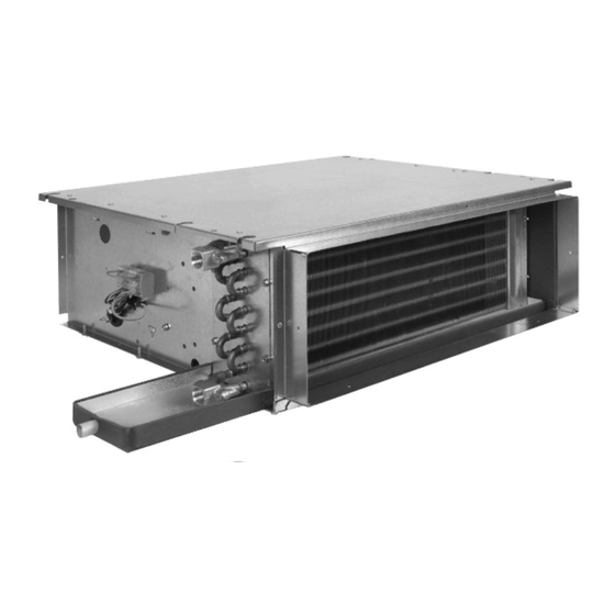
- Page 1 Installation Operation Maintenance UniTrane™ FCD ducted fan coil units Sizes 101-103-203-204-304-306-406-408-508-512-612-721 UniTrane™ FED ducted fan coil units Sizes 100-200-300-400-500-600 July 2013...
-
Page 2: General Information
7 days of delivery, claiming for the described damage. A copy CAUTION! : Indicates a potentially of this letter must be sent to Trane hazardous situation which, if not Epinal Operations - Claims team. avoided, may result in minor or moderate injury. - Page 3 General Information Warranty Maintenance contract Training Warranty is based on the general It is strongly recommended that you To assist you in obtaining the best terms and conditions of the sign a maintenance contract with use of it and maintaining it in manufacturer.
-
Page 4: Table Of Contents
Contents General information Installation Unit identification General data Operating limits (temperature and airflow) Water quality recommendations Handling the unit Mounting the accessories Mounting the unit in the ceiling Ductwork connection Water connection Condensate drainage connection Electrical connection Connecting the thermostats Main power supply External static pressure and airflow curves Water pressure drop curves... -
Page 5: Unit Identification
Installation Unit identification unit model size, coil type, presence of an electric heater, motor type, Units arrive on site with an unit handing, speed wiring, and so identification sticker with on. (See Figure 1) pictograms, which clearly indicates important information such as the customer order number, job name, Figure 1 - Unit identification sticker FCD204AWH5RJW1WABWWWAAWWW2EGW... - Page 6 Installation ‚ = Indicates the unit description = Indicates the ZN control configuration program 2-pipe cooling only 4-pipe 2-pipe heating only Zone control 2-pipe cooling + electric heater Cascade control 2-pipe changeover, 2-way valve 2-pipe changeover, 3-way valve 2-pipe changeover + electric heater, 2-way valve 2-pipe changeover + electric heater, 3-way valve ƒ...
-
Page 7: General Data
Installation General data Table 1 - General data - FCD without air connections 230V/50Hz/1pH, Reversible coil, 2 Pipes Speed at ESP = 0Pa Unit size Airflow (1) (m3/h) 1004 1110 1329 1411 2031 Standard coil, cooling mode Air inlet conditions : 27°C/47%, Water : 7/12°C, Constant delta T° Total/sensible cooling capacity (1) (kW) - Page 8 Installation Table 2 - General data - FCD with inlet/discharge air connections (Dia. 200mm) and EU3 filter 230V/50Hz/1pH, Reversible coil, 2 Pipes Speed at ESP = 50Pa Unit size 204 (*) 304 (*) Airflow (1) (m3/h) 1990 Standard coil, cooling mode Air inlet conditions : 27°C/47%, Water : 7/12°C, Constant delta T°...
- Page 9 Installation Table 3 - General data - FED without air connections 230V/50Hz/1pH, Reversible coil, 2 Pipes Speed at ESP = 0Pa Unit size Airflow (1) (m3/h) 1014 1591 1591 Standard coil, cooling mode Air inlet conditions : 27°C/47%, Water : 7/12°C, Constant delta T° Total / sensible cooling capacity (1) (kW) 1.4 / 1.1...
- Page 10 Installation Table 4 - General data - FED with inlet/discharge air connections (Dia. 200mm) and EU3 filter 230V/50Hz/1pH, Reversible coil, 2 Pipes Speed at ESP = 50Pa Unit size Airflow (1) (m3/h) Standard coil, cooling mode Air inlet conditions : 27°C/47%, Water : 7/12°C, Constant delta T° Total / sensible cooling capacity (1) (kW) 0.65 / 0.5...
-
Page 11: Operating Limits (Temperature And Airflow)
Water temperature must not treatment specialist be engaged to exceed 95°C. determine what water treatment, if Minimal water temperature any, is required. Trane assumes no depends on glycol percentage. responsibility for equipment failures which result from untreated or improperly treated water, or saline... -
Page 12: Handling The Unit
Installation Handling the unit Mounting the accessories WARNING! Wear protection gloves Mount all accessories before when handling the unit. When mounting the unit in the ceiling. removing the unit from its pallet, do Each accessory available for the fan not handle it by pipes, spigots, coils is supplied with its connection valves, drain pan, control panel, or diagram. - Page 13 Installation Adjusting the 60-130 m /h airflow Figure 4 - Fresh air controller membrane controller WARNING! Ensure that the plastic membrane is always positioned as indicated in Figure 4. Adjust the fresh air controller (ø 125 mm only) by placing the two plastic restrictors as indicated in Figure 5.
-
Page 14: Mounting The Unit In The Ceiling
Installation Mounting rubber isolators Mounting the unit in the 4 rubber isolators are supplied, ceiling fixed on the drain pan. Mount the Two methods can be used to mount isolators on the casing, below the the unit in the ceiling. A minimum fixation hole, as shown in Figure 6. - Page 15 Installation Figure 7 - Hole locations Figure 8 - Clearance recommendations (mm) (mm) (mm) (mm) FCD 101-103-203-204-304-306-406-408-508-512-612 FED 100-200-300-400-500-600 FCD 721 Table 5 - Drilling distances Number of Ø threaded Ø hole suspension points rods (1) Unit size (mm) (mm) (mm) (mm) (mm)
- Page 16 Installation Mount the unit, with a slight slope CAUTION! If the unit is not towards the drain pan outlet as mounted with a slight slope, the shown in Figures 9 and 10. Ensure condensates will not drain correctly that sufficient service access is through the hole provided.
-
Page 17: Ductwork Connection
194 x 238 x 418 mm 568 mm 798 mm 948 mm 1098 mm 1398 mm 1398 mm Rectangular connection for Trane discharge grille (80 mm deep) 152 x 152 x 152 x 403 mm 503 mm 803 mm UNT-SVX10G-E4... - Page 18 194 x 1098 194 x 1398 194 x 418 mm 194 x 568 mm 194 x 798 mm 194 x 948 mm Rectangular connection for Trane discharge grille (80 mm deep) 152 x 403 mm 152 x 503 mm 152 x 803 mm...
-
Page 19: Water Connection
Installation Water connection Figure 11 - Vent and drain positions on straight or inclined coil Refer to Figure 11 to locate and identify the inlet and outlet water connections. CAUTION! The coil headers are not designed to withstand the torque necessary to tighten the connector. - Page 20 Installation Table 8 - Water connection types and diameters W = Without valve Unit size 101/103 203/204 304/306 406/408 508/512 Standard 2-pipe coil Customer connection Ø1/2" Gas Ø1/2" Gas Ø1/2" Gas Ø1/2" Gas Ø1/2" Flat gasket Ø3/4" Flat gasket Ø3/4" Flat gasket High Efficiency 2-pipe coil Customer connection Ø1/2"...
- Page 21 Installation 2 = Factory-mounted 2 way valves Unit size 101/103 203/204 304/306 406/408 508/512 Standard 2-pipe coil Customer leaving water connection Ø1/2" Gas Ø1/2" Gas Ø1/2" Gas Ø1/2" Gas Ø1/2" Flat gasket Ø3/4" Flat gasket Ø3/4" Flat gasket Customer entering water connection Ø1/2"...
- Page 22 Installation Whenever the installation's pipes CAUTION! The unit should not stick out from the auxiliary operate without a valve. Units have condensate tray, the installer must undergone extensive tests for insulate them, as indicated in condensates (NF EN 1397 para 5.3), Figure 12.
-
Page 23: Condensate Drainage Connection
Installation Condensate drainage CAUTION! Make sure there is no counter-slope or debris which would connection prevent condensate drainage. (see Figure 14) Provide a U-trap on the drainage line. It is vital to use tubes that do not become deformed when bent. It is recommended to secure connection between the tube and the drain with a clamp or a collar. - Page 24 Installation Should several units be connected The condensate pump is equipped to the same condensate drain line, with a floating sensor which will respect line design conditions as stop chilled water flow as soon as indicated in Figure 18. the alarm level is reached, while continuing to evacuate condensate As an option, units can be supplied water.
- Page 25 Installation Figure 16 - Condensate pump option for ZN control 1 = Condensate tray 2 = Condensate level sensor 3 = Condensate tube suction 4 = Condensate tube discharge 5 = Vent It is recommended to secure connection between the tube and the drain with a clamp or a collar.
- Page 26 Installation Figure 17 - Condensate drainage with condensate pump for on/off (GP) control or ZN control 10 mm/m 60 mm 10 mm/m A = Position the vent upwards 1 = Water 2 = Air WARNING ! B = No negative discharge UNT-SVX10G-E4...
- Page 27 Installation Table 9 - Condensate pump performances (l/h) Discharge height - Discharge length-L Pump manufacturer Sauerman GP 7 .4 Sauerman GP 7 .0 Sauerman GP Sauerman GP Siccom ZN Siccom ZN Siccom ZN Siccom ZN Figure 18 - Multiple units drainage 10 mm/m >...
-
Page 28: Electrical Connection
(max 30mA) must be installed as a FCD/FED fan coils manufactured by general line protection. Trane comply with CEI regulations. The sensors and changeover Only copper conductors (1.5mm2 capsules must be installed on the min) must be used as unit terminals... - Page 29 2000W 3000W The minimum airflow is ensured for the fan speed selection using the Trane selection tool. CAUTION! Measure airflow above the minimum airflow in the above tables when selecting, on site, a lower speed than those defined from the factory.
- Page 30 Installation Electric heaters shall run with the minimum airflow described in following table. To maintain this minimum airflow the fan motor shall not run below the following voltage. This results in reduced airflow operating range described in the following table. Minimum air flow (m /h) function electric heater Electric heater capacity...
- Page 31 Installation Figure 20 - FED 300 Airflow operating range m3/h A = Airflow pressure drop system curve B = Standard selection operating system zone Figure 21 - FED 300 with Electric Heater 500 W - 7500 W - 1000 W A = 160 m /hr minimum airflow for 1000 W B = Not allowed operating system...
-
Page 32: Connecting The Thermostats
Location of thermostats thermostats Do not install thermostats near or above a source of heat (i.e. direct For more information about Trane sunlight, hot lamps or radiator). On/Off controls or Trane DDC Thermostats should be installed at controls please refer to controls least 1.5 m above floor level. - Page 33 Installation Speed selection Figure 24 - Selecting speeds FCD units offer the possibility to select any three from six speeds. Refer to Figures 24-25 to select the speeds to suit the airflow and static pressure required. The speed can be modified directly in the electric control box.
- Page 34 Installation Figure 25 - Interconnection wirings - On/Off controls - thermostat L/M for FCD UNT-SVX10G-E4...
- Page 35 Installation Figure 26 - Interconnection wirings - On/Off controls - thermostat N for FCD UNT-SVX10G-E4...
- Page 36 Installation Figure 27 - Interconnection wirings - On/Off controls - thermostat P for FCD 230V 50Hz TH01 - P 2 tubes chaud - 2 warme Rohre - 2 pipe heating - 2 tubi caldo - 2 buizen verwarming- 2 tubos calentadador 230V 50Hz 230V 50Hz 2 tubes froid -...
- Page 37 Installation Figure 28 - Interconnection wirings - On/Off controls - thermostat P for FCD UNT-SVX10G-E4...
- Page 38 Installation Figure 29 - Interconnection wirings - On/Off controls - thermostat P/E for FCD UNT-SVX10G-E4...
-
Page 39: Main Power Supply
Installation Main power supply Figure 31- Units with modulating/communicating control with/without electric heater It is the installer's responsibility to ensure that units are protected by an electrical disconnect device such as a fuse or circuit breaker. Standard units with on/off control are supplied without any protection, and a fuse disconnect switch is available as an option. -
Page 40: External Static Pressure And Airflow Curves
Installation External static pressure and airflow curves Figure 32 - External Static Pressure - FCD 101 with G3 filter m3/h D1 = Discharge plenum only, ø200 mm air duct connection(s) D2 = Discharge plenum + return plenum, ø200 mm air duct connections(s) Figure 33 - External Static Pressure - FCD 103 with G3 filter m3/h D1 = Discharge plenum only, ø200 mm air duct connection(s) - Page 41 Installation Figure 34 - External Static Pressure - FCD 203 with G3 filter m3/h D1 = Discharge plenum only, ø200 mm air duct connection(s) D2 = Discharge plenum + return plenum, ø200 mm air duct connections(s) Figure 35 - External Static Pressure - FCD 204 with G3 filter m3/h D1 = Discharge plenum only, ø200 mm air duct connection(s) D2 = Discharge plenum + return plenum, ø200 mm air duct connections(s)
- Page 42 Installation Figure 36 - External Static Pressure - FCD 304 with G3 filter m3/h D1 = Discharge plenum only, ø200 mm air duct connection(s) D2 = Discharge plenum + return plenum, ø200 mm air duct connections(s) Figure 37 - External Static Pressure - FCD 306 with G3 filter m3/h D1 = Discharge plenum only, ø200 mm air duct connection(s) D2 = Discharge plenum + return plenum, ø200 mm air duct connections(s)
- Page 43 Installation Figure 38 - External Static Pressure - FCD 406 with G3 filter m3/h D1 = Discharge plenum only, ø200 mm air duct connection(s) D2 = Discharge plenum + return plenum, ø200 mm air duct connections(s) Figure 39 - External Static Pressure - FCD 408 with G3 filter 1000 1200 m3/h...
- Page 44 Installation Figure 40 - External Static Pressure - FCD 508 with G3 filter 1000 1200 1400 m3/h D1 = Discharge plenum only, ø200 mm air duct connection(s) D2 = Discharge plenum + return plenum, ø200 mm air duct connections(s) Figure 41 - External Static Pressure - FCD 512 with G3 filter 1000 1200 1400...
- Page 45 Installation Figure 42 - External Static Pressure - FCD 612 with G3 filter 1000 1200 1400 1600 1800 m3/h D1 = Discharge plenum only, ø200 mm air duct connection(s) D2 = Discharge plenum + return plenum, ø200 mm air duct connections(s) Figure 43 - External Static Pressure - FCD 721 with G3 filter D1 = Discharge plenum only, ø200 mm air duct connection(s) D2 = Discharge plenum + return plenum, 0200mm air duct connections(s)
- Page 46 Installation Figure 44 - External Static Pressure - FED 100 D1 = Discharge plenum only, ø200 mm air duct connection(s) D2 = Discharge plenum + return plenum, ø200 mm air duct connections(s) Figure 45 - External Static Pressure - FED 200 D1 = Discharge plenum only, ø200 mm air duct connection(s) D2 = Discharge plenum + return plenum, ø200 mm air duct connections(s) UNT-SVX10G-E4...
- Page 47 Installation Figure 46 - External Static Pressure - FED 300 D1 = Discharge plenum only, ø200 mm air duct connection(s) D2 = Discharge plenum + return plenum, ø200 mm air duct connections(s) Figure 47 - External Static Pressure - FED 400 1000 1200 D1 = Discharge plenum only, ø200 mm air duct connection(s)
- Page 48 Installation Figure 48 - External Static Pressure - FED 500 1000 1200 1400 1600 1800 D1 = Discharge plenum only, ø200 mm air duct connection(s) D2 = Discharge plenum + return plenum, ø200 mm air duct connections(s) Figure 49 - External Static Pressure - FED 600 1000 1200 1400...
-
Page 49: Water Pressure Drop Curves
Installation Water pressure drop curves Figure 50 - Water pressure drop through the coils - Cooling mode, Standard 2-pipe coil 5000 1000 1 = FCD Size 101-103 / FED 100 5 = Size 508-512 / FED 500 2 = FCD Size 203-204 / FED 200 6 = Size 612 / FED 600 3 = FCD Size 304-306 / FED 300 7 = Size 721... - Page 50 Installation Figure 52 - Water pressure drop through the coils - Heating mode, Standard 2-pipe coil 34 5 1000 5000 1 = FCD Size 101-103 / FED 100 5 = Size 508-512 / FED 500 2 = FCD Size 203-204 / FED 200 6 = Size 612 / FED 600 3 = FCD Size 304-306 / FED 300 7 = Size 721...
- Page 51 Installation Figure 54 - Water pressure drop through the coils - Heating mode, Standard 4-pipe coil For pressure drops of the 4-pipe coil in cooling mode, see Figure 52. 1000 5000 1 = FCD Size 101-103 Standard capacity / FED 100 2 = FCD Size 203-204 Standard capacity / FED 200 3 = FCD Size 304-306 Standard capacity /...
- Page 52 Installation Table 14 - Pressure drop through the valves - FCD Cooling / Heating - 2-pipe coil 304/306 101/103 406/408 Unit size 203/204 508/512 612/721 Connections (inches) 2-way on/off control Kv valve 2-way ZN 523 control Kv valve 3-way on/off control Kv valve 3-way ZN523 control Kv valve Heating (4-pipe coil) Connections (inches)
- Page 53 Installation Figure 55- Pressure drop through the valves UNT-SVX10G-E4...
-
Page 54: Pre-Start Checkout
Installation Pre-start checkout • Condensate trays are connected. This work should only be undertaken by a qualified • No dirt in the condensate tray. 1. Check the units are correctly electrician and the unit should be • Hydraulic connections carried installed and have a slight slope externally isolated before the out, insulated, and tightened. -
Page 55: Maintenance
Maintenance WARNING! When performing any Figure 56 - Electric heater Accessing the filter maintenance on the unit, disconnect Figure 58 - Handling the filter - unit power supply to the unit. Wear without inlet air connection protective gloves to avoid injury. To remove the filter: Servicing the electric 1. - Page 56 Maintenance On the unit with plenum at the inlet, To put the filter back, hold the filter at the top of the frame with one To remove the filter (1): hand. Push to clip the filter back 1) Unscrew the two tabs (4) and into place at the bottom with the push them backwards.
-
Page 57: Servicing The Coil
Maintenance Servicing the coil Figure 61 - Inclined coil To replace or clean a water coil: 1. Disconnect the drain pan piping, the water inlet and outlet, and unplug the condensate pump supply wire, if present. 2. Remove the filter and then remove the coil access panel or panels, depending on unit size and configuration. -
Page 58: Servicing The Fan Motor Assembly
Maintenance Servicing the fan motor Note: If the option “Accessibility pack” has been chosen: assembly 1. Remove the two lower screws from the fan motor assembly (1, To replace a fan board assembly: Figure 62) and unscrew (1/2 turn) 1. Remove the filter and the fan the two screws at the top (2, board access panel(s), depending Figure 62). -
Page 59: Periodic Maintenance
Maintenance Periodic maintenance Annual maintenance Use random sampling of the units It is recommended to carry out the installed in the building (between 3 following maintenance procedures and 5%) to check: at the stipulated frequencies to ensure the unit operates correctly. 1) the state of cleanliness of the condensate trays. -
Page 60: User Guide
User Guide Thermostats type L, M, N, P , E for FCD Thermostat type L Thermostat type M and N Thermostat type P HEAT ON OFF ON OFF ON OFF COOL 1 = ON/OFF selector 2 = Fan speed selection: 1 = Low fan speed 2 = Medium fan speed 3 = High fan speed... - Page 61 Notes UNT-SVX10G-E4...
- Page 62 Notes UNT-SVX10G-E4...
- Page 63 Notes UNT-SVX10G-E4...
- Page 64 HVAC systems, comprehensive building services, and parts. For more information, visit www.Trane.com. Trane has a policy of continuous product and product data improvement and reserves the right to change design and specifications without notice. © 2013 Trane All rights reserved...