Table of Contents
Advertisement
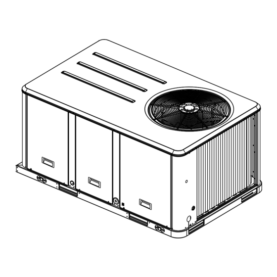
Installation, Operation,
and Maintenance
Packaged Rooftop Air Conditioners
Precedent™- Electric/Electric
3 – 10Tons – 60 Hz
Model Numbers
Only qualified personnel should install and service the equipment. The installation, starting up, and servicing of heating, ventilating, and air-
conditioning equipment can be hazardous and requires specific knowledge and training. Improperly installed, adjusted or altered equipment
by an unqualified person could result in death or serious injury. When working on the equipment, observe all precautions in the literature and
on the tags, stickers, and labels that are attached to the equipment.
September 2013
TSC037E - TSC067E
TSC036E - TSC060E
TSC072F - TSC120F
SAFETY WARNING
RT-SVX22M-EN
THC037E - THC067E
THC036E - THC072E
THC120E
THC048F - THC102F
Advertisement
Table of Contents
Troubleshooting

Related Manuals for Trane TSC037E


Summary of Contents for Trane TSC037E
- Page 1 Installation, Operation, and Maintenance Packaged Rooftop Air Conditioners Precedent™- Electric/Electric 3 – 10Tons – 60 Hz Model Numbers TSC037E - TSC067E THC037E - THC067E TSC036E - TSC060E THC036E - THC072E TSC072F - TSC120F THC120E THC048F - THC102F SAFETY WARNING Only qualified personnel should install and service the equipment. The installation, starting up, and servicing of heating, ventilating, and air- conditioning equipment can be hazardous and requires specific knowledge and training.
-
Page 2: Important Environmental Concerns
RT-SVX22L-EN (12 July 2013) Responsible Refrigerant Practices! • 5GII update - Cooling and Gas/Electric -T/YHC036, 048, Trane believes that responsible refrigerant practices are important to the environment, our customers, and the air RT-SVX22L-EN (13 May 2013) conditioning industry. All technicians who handle •... -
Page 3: Table Of Contents
Table of Contents Model Number Description Heat Units ......27 ....5 Model Number Notes . - Page 4 Table of Contents Units with Belt Drive Indoor Fan ..44 Method 2 ......57 Units with Direct Drive Indoor Fan - Electro- Zone Temperature Sensor (ZTS) Service Indi- mechanical Control .
-
Page 5: Model Number Description
Options Economizer, Dry Bulb 0-100% Convertible with Barometric Relief No Communications Interface Digit 4,5,6 - Nominal Gross Economizer, Reference Enthalpy Trane Communications Interface 0-100% without Barometric Relief LonTalk® Communications Interface Cooling Capacity (MBh) Economizer, Reference Enthalpy Novar 2024 Controls 3Ton... -
Page 6: Model Number Notes
Model Number Description 3 Phase (3-5 ton w/Dehumidification) = Belt Discharge Air Sensing 18. Novar Sensor utilized with Drive Motor Condensate Drain Pan Overflow Digit 21 = (4) Novar 3051 Controls 3 Phase (7½-10 ton) = Ultra High Efficiency Switch without Zone Sensor. -
Page 7: Model Number Description - 17 Plus
Model Number Description - 17 Plus Model Number Description - 17 Plus Digit 1 - Unit Type Digit 14 - Fresh Air Selection Digit 19 - Disconnect/Circuit Breaker (three-phase only) DX Cooling No Fresh Air DX Cooling, Gas Heat Manual Outside Air Damper 0-50% No Disconnect/No Circuit Breaker Motorized Outside Air Damper Unit Mounted Non-Fused... -
Page 8: Model Number Notes
Model Number Description - 17 Plus Condensate Drain Pan Overflow disconnect/circuit breaker Switch options. Fan Failure Switch and Condensate 7. Requires use of Disconnect or Drain Pan Overflow Switch Discharge Air Sensing Circuit Breaker. Condensate Drain Pan Overflow Not Available Switch High Efficiency Clogged Filter Switch... -
Page 9: General Information
General Information Unit Inspection Compressor Nameplate As soon as the unit arrives at the job site The nameplate for the compressors are located on the side of the compressor. • Verify that the nameplate data matches the data on the sales order and bill of lading (including electrical data). -
Page 10: System Input Devices & Functions
FFS (Fan Failure Switch) If air flow through the unit is not is powered by 24 VAC. proven by the differential pressure switch connected to the RTCI - ReliaTel™ Trane Communication RTOM (factory set point 0.07 “w.c.) within 40 seconds Interface (Optional) -
Page 11: Low Pressure Control
General Information Compressor Disable (CPR1/2) Power Exhaust Control (Optional) This input incorporates the low pressure control (LPC) of ReliaTel Control each refrigeration circuit and can be activated by opening The power exhaust fan is started whenever the position of a field supplied contact installed on the LTB. the economizer dampers meets or exceed the power If this circuit is open before the compressor is started, the exhaust setpoint when the indoor fan is on. -
Page 12: Evaporator Frost Control
(X1310004001) is set to open at 135ºF .The timed override with override cancellation. It is used with a supply air duct sensor (X1310004002) is set to open at Trane Integrated Comfort™ building management 240ºF .The control can be reset after the temperature has system. -
Page 13: Discharge Line Temp Switch (Dlts)
General Information closing a field supplied contact installed in parallel with Maintenance Instructions provided with the literature the FOS. package for this unit. If this circuit is closed before the compressor is started, the In order for the supply air smoke detector or return air compressor will not be allowed to operate. -
Page 14: Unit Dimensions
Unit Dimensions Unit Clearances installation.These clearances are the minimum distances necessary to assure adequate serviceability, cataloged unit capacity, and peak operating efficiency. Figure 1, p. 14 illustrates the minimum operating and service clearances for either a single or multiple unit Figure 1. - Page 15 Unit Dimensions Figure 2. 3-5 ton standard efficiency, 3 ton high efficiency Note: All dimensions are in inches/millimeters. Figure 3. 3-5 ton standard efficiency, 3 ton high efficiency - roof curb Note: All dimensions are in inches/millimeters. 44 MM 44 MM 1038 1038 MM 1053...
- Page 16 Unit Dimensions Figure 4. 3-5 ton standard efficiency, 3 ton high efficiency - unit clearance and roof opening Note: All dimensions are in inches/millimeters. CLEARANCE 36” (914 MM) Figure 5. 6, 7½ (single) ton standard efficiency, 4 - 5 ton high efficiency Note: All dimensions are in inches/millimeters.
- Page 17 Unit Dimensions Figure 6. 6, 7½ (single) ton standard efficiency, 4 - 5 ton high efficiency - roof curb Note: All dimensions are in inches/millimeters. (356 MM) (2130 MM) Figure 7. 6, 7½ (single) ton standard efficiency, 4 - 5 ton high efficiency - unit clearance and roof opening Note: All dimensions are in inches/millimeters.
- Page 18 Unit Dimensions Figure 8. 7½ ton (dual) - 10 ton standard efficiency, 6-8½ (microchannel) ton high efficiency, 6 ton dehumidification Note: All dimensions are in inches/millimeters. Figure 9. 7½ ton (dual) - 10 ton standard efficiency, 6-8½ (microchannel) ton high efficiency, 6 ton dehumidification roof curb Note: All dimensions are in inches/millimeters.
- Page 19 Unit Dimensions Figure 10. 7½ ton (dual) - 10 ton standard efficiency, 6-8½ (microchannel) ton high efficiency, 6 ton dehumidification - unit clearance and roof opening) Note: All dimensions are in inches/millimeters. Figure 11. 10 ton high efficiency Note: All dimensions are in inches/millimeters. RT-SVX22M-EN...
- Page 20 Unit Dimensions Figure 12. 10 ton high efficiency - roof curb Note: All dimensions are in inches/millimeters. 18 1/2” (470 MM) 6 5/8” 83 7/8” (168 MM) 1” (2130 MM) (25 MM) 34 3/8” 56 3/8” (873 MM) (1432 MM) 18 1/2”...
-
Page 21: Installation
Installation Pre-Installation If an element has detached from its ceramic insulator, carefully put it back into place. Replace the heater elements if they present symptoms WARNING noted in item Step 2 Step 3 above. Fiberglass Wool! Procedure Product contains fiberglass wool. Disturbing the insulation in this product during installation, maintenance or repair will expose you to airborne WARNING... - Page 22 Installation Table 1. Maximum unit & corner weights (lbs) and center of gravity dimensions (in.) - cooling models Maximum Model Weights Corner Weights Center of Gravity (in.) Unit Model No. Shipping Length Width TSC036E/THC036E TSC048E TSC060E TSC072F 7½ TSC090F 7½ TSC092F 8½...
-
Page 23: Foundation
Installation (a),(b) Table 2. Factory installed options (fiops)/accessory net weights (lbs) TSC036E-060E THC047E-067E THC092F- THC036E/ THC048E/F- TSC072F-102F 102F, THC037E 060E/F THC072E/F TSC120F THC120E Net Weight Net Weight Net Weight Net Weight Net Weight 7½, 8½-10 Accessory 3-5 Ton 4-5 Ton 6-8½... - Page 24 Installation Figure 17. 4-6, 7½, 8½ (Microchannel) ton high Figure 20. 4-6, 7½, 8½ (Microchannel) ton high efficiency units and 6-10 ton standard efficiency units and 6-10 ton standard efficiency units - Horizontal supply & return efficiency units - downflow supply & return air openings air openings w/ through the base utilities Figure 21.
-
Page 25: Roofcurb
Installation Step-by-step curb assembly and installation instructions Table 3. Clearance required from duct to combustible ship with each accessory roof curb kit. Follow the surfaces instructions carefully to assure proper fit-up when the unit is set into place. Note: To assure proper condensate flow during Clearance required from duct to operation, the unit (and curb) must be level. -
Page 26: Rigging
Installation • For “built-up” curbs supplied by others, gaskets must Figure 25. Fork pockets - 10 ton high efficiency units be installed around the curb perimeter flange and the supply and return air opening flanges. Rigging A Rigging illustration and Center-of-Gravity dimensional data table is shown in Figure 15, p. -
Page 27: Factory Installed Economizer
Installation • Install and connect a condensate drain line to the Note: Certain unit/electric heater combinations require a evaporator drain connection. limit switch change out for horizontal airflow applications. Refer to the following instructions to Factory Installed Economizer determine if this process is required for the unit undergoing installation. -
Page 28: Tco-A Instructions
Installation Note: If unit is equipped with Return Air Smoke Detector, any in this table, skip steps 1 through 3 and go on to next refer to field conversion instructions for horizontal step in the installation process. discharge before installing return air duct. 1. -
Page 29: Return Air Smoke Detector
Installation Return Air Smoke Detector Figure 34. Horizontal view 2 The factory installed Return Air Smoke Detector is installed in the downflow discharge position. No additional field setup is required. If a unit is to be converted to horizontal discharge, the following conversion must be performed: 1. -
Page 30: Electric Heat Requirements
Installation 2. Remove the support panel that the condensate drain pan exits through. WARNING 3. Slide the condensate drain pan out of the unit and Proper Field Wiring and Grounding rotate 180°. Required! 4. Slide the condensate drain pan back into the unit, align All field wiring MUST be performed by qualified the drain with the grommeted opening in the rear personnel. -
Page 31: Filter Installation
Installation Figure 35. Condensate trap installation NOTICE: Use Copper Conductors Only! Unit terminals are not designed to accept other types of conductors. Failure to use copper conductors could result in equipment damage. Important: If the unit is not equipped with an optional 38.1 factory installed non-fused disconnect switch or circuit breaker, a field supplied... -
Page 32: Field Installed Control Wiring
Installation Field Installed Control Wiring disconnect switch (UDC) or circuit breaker (UCB). If neither a factory mounted non-fused disconnect switch (UDC) or An overall layout of the various control options available circuit breaker (UCB) was factory mounted, field wiring with the required number of conductors for each control connections should be terminated in the control box at device is illustrated in Figure 52, p. -
Page 33: Controls Using Dc Analog Input/Outputs (Standard Low Voltage Multi Conductor Wire)
Installation Table 6. Electromechanical thermostat 24V AC Figure 38. ReliaTel™ conventional thermostat field conductors with Electromechanical unit wiring diagrams Distance from Unit to RTRM Control Recommended Wire Size 0 - 30 feet 22 gauge 0 - 9.1 m .33 m2 31 - 50 feet 20 gauge 9.5 - 15.2 m... - Page 34 Installation Figure 41. ReliaTel™ relative humidity sensor Figure 42. ReliaTel humidistat (dehumidification (dehumidification option) option) Figure 43. Electromechanical control customer low voltage routing (all units except 10 ton high efficiency) Figure 44. ReliaTel control customer low voltage routing (all units except 10 ton high efficiency) RT-SVX22M-EN...
- Page 35 Installation Figure 45. ReliaTel™ (without TBUE) control customer wire routing (10 ton high efficiency) Figure 46. ReliaTel (with TBUE) control customer wire routing (10 ton high efficiency) RT-SVX22M-EN...
- Page 36 Installation Figure 47. Electromechanical (without TBUE) control customer wire routing (10 ton high efficiency) Figure 48. Electromechanical (with TBUE) control customer wire routing (10 ton high efficiency) RT-SVX22M-EN...
-
Page 37: Smoke Detector Customer Low Voltage Wir
Installation Smoke Detector Customer Low Figure 50. Up to 10 HVAC units If you have more than 5 HVAC units, you can Voltage Wiring connect all the supplies together on one power supply (up to 10 HVAC units), and all the returns When interlocking System Sensor smoke detectors together (up to 10 HVAC units) on another power together, all of the detectors must be powered from the... - Page 38 Installation Figure 51. Examples RT-SVX22M-EN...
- Page 39 Installation Figure 52. Typical field wiring diagrams for optional controls (ReliaTel™ only) BA YSENS075* BA YSENS075* BA YSENS108* BA YSENS106* BA YSENS110* BA YSENS119* BAYSENS073* BAYSENS074* BAYSENS075* ASYSTAT669A OPTIONAL REMOTE SENSOR RT-SVX22M-EN...
- Page 40 Installation Table 8. Temperature vs. resistance Temperature Degrees F° Degrees C° Nominal Resistance -20° -28.9° 170.1 K - Ohms -15° -26.1° 143.5 K - Ohms -10° -23.3° 121.4 K - Ohms -5° -20.6° 103.0 K - Ohms 0° -17.8° 87.56 K - Ohms 5°...
-
Page 41: Pre-Start
Pre-Start Use the checklist provided below in conjunction with the Volt 1 + Volt 2 + Volt 3 “General Unit Requirements” checklist to ensure that the AV (Average Voltage)= unit is properly installed and ready for operation. V1, V2, V3 = Line Voltage Readings WARNING VD = Line Voltage reading that deviates the farthest from Hazardous Voltage w/Capacitors! -
Page 42: Compressor Crankcase Heaters (Optional)
Pre-Start “Line” side of the optional factory mounted disconnect Before starting the unit in the “Cooling” mode, set the switch to the “Off” position. system switch to the “Off” position and turn the main power disconnect to the “On” position and allow the •... -
Page 43: Test Modes
Pre-Start Table 9. Service test guide for component operation Multi-Speed Fan Test Step Mode Econ Comp 1 Comp 2 Heat 1 Heat 2 Resistance Output Output Minimum Position Setpoint 0% Ω 2.2K Minimum Selectable Ventilation Economizer Ω Open 3.3K Test Open Cool Minimum Ω... -
Page 44: Unit Start-Up
Unit Start-Up Verifying Proper Air Flow 1. Measure the supply and return duct static pressure and sum the resulting absolute values, 2. Use the accessory pressure drop table in the Service WARNING Facts, to calculate the total static pressure drop for all of the accessories installed on the unit;... -
Page 45: Units With Direct Drive Indoor Fan - Electromechanical Control
Unit Start-Up Once the supply fan has started, check for proper rotation. installed, before starting the SERVICETEST disable the The direction of rotation is indicated by an arrow on the fan Economizer by disconnecting the 4 pin power connector housing. located at the base of the Economizer Control (ECA). -
Page 46: Units With Constant Cfm Direct Drive Indoor
Unit Start-Up Electro Mechanical Control: Units with Constant CFM Direct Drive Using the ServiceTest Guide perform the proper test mode connections. Indoor Fan Once the supply fan has started, determine the total Much of the systems performance and reliability is closely system airflow (CFM) by (ReliaTel™/Electromechanical): associated with, and dependent upon having the proper airflow supplied both to the space that is being... -
Page 47: Vhr Relay Output
Unit Start-Up 1. In the indoor fan compartment, locate the R136 Note: The RTRM is designed to maintain a selectable potentiometer on the RTOM circuit board (also supply air temperature of 40°F to 90°F with a +/- designated “DA COOL - FAN SPD”). Also, locate the 3.5°F deadband. -
Page 48: Supply Duct Static Pressure Control
Unit Start-Up Example: ranges are from 50°F to 90°F . When the zone temperature meets or exceeds the MWU setpoint, the unit will switch to Supply Duct Static setpoint = 2.0" w.c. (RTAM) the “Cooling” mode.The economizer will be held closed Deadband = 0.2"... -
Page 49: Return Air Smoke Detector
Unit Start-Up 4. Reset based on Outdoor AirTemperature - When DIP This will set the minimum damper position at an Switch #3 and #4 are “On” , a selectable supply air reset intermediate point of fan operation range of damper setpoint of 0°F to 100°F via RTAM potentiometer or for this setting is 0-75%. -
Page 50: Compressor Start-Up
Unit Start-Up Scroll Compressors. WARNING a. Once each compressor has started, verify that the rotation is correct. If a scroll compressor is rotating Rotating Components! backwards, it will not pump and a loud rattling During installation, testing, servicing and sound can be observed. troubleshooting of this product it may be necessary to b. -
Page 51: Final System Setup
Unit Start-Up ReliaTel™ Control. Using the ServiceTest Guide in Table 9, p. 43, continue the SERVICETEST start-up procedure for each compressor circuit. Momentarily jump across theTest 1 &Test 2 terminals on LTB one additional time if continuing from previous component start-up or until the desired start-up componentTest is started. -
Page 52: Maintenance
Maintenance Fan Belt Adjustment - Belt Drive Note: Actual belt deflection “force” must not exceed the maximum “force” value shown in Figure 54, p. Units 7. Recheck the belt tension at least twice during the first 2 to 3 days of operation. Belt tension may decrease until the new belts are “run in”... -
Page 53: Return Air Smoke Detector Maintenance
Maintenance Return Air Smoke Detector Maintenance system superheat. For guidelines, refer to the “Compressor Start-Up” section. Airflow through the unit is affected by the amount of dirt Important: Do not release refrigerant to the and debris accumulated on the indoor coil and filters.To atmosphere! If adding or removing insure that airflow through the unit is adequate for proper refrigerant is required, the service... -
Page 54: Microchannel (Mche) Coils
Maintenance Microchannel (MCHE) Coils solution BUT DO NOT EXCEED 150ºF maximum to improve its cleansing capability. NOTICE: WARNING Coil Damage! Hazardous Pressures! DO NOT use any detergents with microchannel Coils contain refrigerant under pressure. When cleaning condenser coils. Use pressurized water or air ONLY, coils, maintain coil cleaning solution temperature under with pressure no greater than 600psi. -
Page 55: Annual Maintenance
Maintenance Annual Maintenance Clean and repaint any corroded surface. Final Process For future reference, you may find it helpful to record the unit data requested in the blanks provided. Complete Model Number: Unit Serial Number: Wiring Diagram Numbers (from unit control panel): Connections: Schematics: Table 13. -
Page 56: Troubleshooting
Troubleshooting ReliaTel™ Control operations for each mode, to assist in verifying proper operation. Make the necessary repairs and proceed to Step 7 Step The RTRM has the ability to provide the service personnel with some unit diagnostics and system status information. 7. -
Page 57: Cooling Failure
Troubleshooting Cooling Failure Cool Operating = approximately 32 VDC Cool Off = less than 1 VDC, approximately 0.75 VDC • Cooling and heating set point (slide pot) on the zone sensor has failed. Refer to the “Zone SensorTest Cooling Failure = voltage alternates between 32 VDC & Procedure”... -
Page 58: Clogged Filter Switch
Troubleshooting The RTRM will ignore the closing of this Normally Open Table 14. Cooling setpoint and heating setpoint switch for 2 (±1) minutes.This helps prevent nuisance Nominal ZTEMP SERVICE LED indications.The exception is the LED will Zone Temperature Resistance flash 40 seconds after the fan is turned “On” if the Fan 75°... -
Page 59: Programmable & Digital Zone Sensor Test
Troubleshooting % RH WARNING Hazardous Voltage! 10.4 Disconnect all electric power, including remote 12.0 disconnects before servicing. Follow proper lockout/ 13.6 tagout procedures to ensure the power can not be 15.2 inadvertently energized. Failure to disconnect power before servicing could result in death or serious injury. 16.8 1. -
Page 60: Electro Mechanical Control
Troubleshooting Electro Mechanical Control 1. Using the “Test Mode” described in the “System Start- Up” section, put the unit into the economizer mode and verify that the economizer actuator (ECA) drives WARNING fully open (approximately 90 seconds). Live Electrical Components! 2. - Page 61 Troubleshooting Please follow steps sequentially unless directed differently in solution. Table 15. Troubleshooting for direct drive plenum fan Step Symptom or Test Probable Cause and Solution If obstruction is present, remove Obstruction blocking power from unit and remove operation of evaporator obstruction.
-
Page 62: Unit Wiring Diagrams Numbers
Unit Wiring Diagrams Numbers Note: Wiring diagrams can be accessed using e-Library by entering the diagram number in the literature order number search field or by contacting technical support. Table 16. Unit wiring diagram numbers Schematic Type Drawing Number Description 4366-7216 THC(037-067) 4366-4568... - Page 63 Unit Wiring Diagrams Numbers Table 16. Unit wiring diagram numbers (continued) Schematic Type Drawing Number Description 4366-7336 THC(037) (230V) 4366-8243 THC037E, 17 Plus with Multi-Zone VAV 4366-7338 THC(047-067) (230V) 4366-8245 THC (047,067)E, 17 Plus with Multi-Zone VAV 4366-8251 THC(092-120)E, ReliaTel Controls with Multi-Zone VAV 4366-4559 T(S,H)C(036-060)E,F (1-Phase), ReliaTel Controls 4366-5182...
-
Page 64: Limited Warranty
If any part of your Combination Electric/ Electric Air concerning this limited warranty, contact: Conditioner fails because of a manufacturing defect within Trane five years from the date of the original purchase, 2701 Wilma Rudolph Blvd. Warrantor will furnish without charge the required replacement part. -
Page 65: Electric Air Conditioner
Limited Warranty Electric Air Conditioner Trane 2701 Wilma Rudolph Blvd. TCY, TCX, TCC, TCD, TCH, TCK, TCM, TCP , Clarksville,TN 37040-1008 TSC and THC (Parts Only) Models Less Attention: Manager, Product Service Than 20 Tons for Commercial Use* GW-606-4800 This warranty is extended byTrane to the original... - Page 68 The manufacturer optimizes the performance of homes and buildings around the world. A business of Ingersoll Rand, the leader in creating and sustaining safe, comfortable and energy efficient environments,the manufacturer offers a broad portfolio of advanced controls and HVAC systems, comprehensive building services, and parts. For more information, visit www.IRCO.com.