Sign In
Upload
Manuals
Brands
Trane Manuals
Air Conditioner
UniTrane Fan Coil
Trane UniTrane Fan Coil Manuals
Manuals and User Guides for Trane UniTrane Fan Coil. We have
1
Trane UniTrane Fan Coil manual available for free PDF download: Installation, Operation And Maintenance Manual
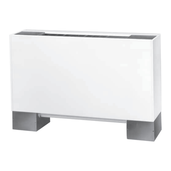
Trane UniTrane Fan Coil Installation, Operation And Maintenance Manual (160 pages)
Brand:
Trane
| Category:
Air Conditioner
| Size: 12.52 MB
Table of Contents
Warnings, Cautions and Notices
2
Table of Contents
3
Model Number Descriptions
7
Unitrane™ Fan Coil/Force Flo™ Cabinet Heater
7
Unitrane™ Fan Coil Low Vertical Model
10
General Information
12
Pre-Installation
13
Receiving and Handling
13
Inspection
13
Packaging/Shipping
13
Identification
13
Handling
13
Receiving Checklist
13
Jobsite Storage
13
Site Preparation
14
Dimensions and Weights
15
Service Clearances
15
Component Data
16
Available Models
17
Model a Vertical Concealed
18
Model B Vertical Cabinet
20
Unit Size
21
No. Fans 1 1 2 2
21
No. Motors
21
Notes
21
Model C Horizontal Concealed
22
Locations. All Duct Collar Dimensions Are to the Outside of the Collar
23
Model D Horizontal Cabinet
24
Model E Horizontal Recessed
26
Model F Vertical Wall Hung Cabinet
28
Model H Vertical Recessed
30
Model J Vertical Slope Top Cabinet
32
Model K Low Vertical Concealed
34
Model L Low Vertical Cabinet
36
Model M Inverted Vertical Cabinet
38
Model N Inverted Vertical Recessed
40
Mode P Compact Concealed
42
Coil Connections
43
Fan Coil Vertical Units
43
Fan Coil Horizontal Units
44
Force Flo Vertical Units
45
Force Flo Horizontal and Inverted Units
46
Fresh Air Opening Locations
47
Horizontal Units
47
Vertical Units
48
Wall Box
49
Projection Panel
50
Installation-Mechanical
51
Installation Checklist
51
Installing the Unit
52
Vertical Units
52
Horizontal Units
52
Cabinet Units
53
Recessed Units
53
Duct Connections
54
Ductwork Recommendations
54
Coil Piping and Connections
55
Factory-Installed Piping Packages
55
Hydronic Coil Piping
56
Connecting Field Piping to Coil
56
Water Piping Connections
56
Connecting to Factory Piping
56
Condensate Drain Connections
56
Condensate Overflow Detection Device
57
Automatic Changeover Sensor
57
Venting the Hydronic Coil
58
External Insulating Requirements
58
Balancing Manual Circuit Setter Valve
58
Installation - Zone Sensors
61
Zone Sensor Options
61
ZN010 Controller Options
61
ZN510, ZN520, UC400 Controller Options
61
Installation Considerations
62
Location
62
Placement
63
Height Requirements
63
Mounting Surfaces
63
Installation
63
Fan Mode Switch
63
Wired Zone Sensor
64
Wireless Zone Sensors
64
Receivers
65
Zone Sensor Settings
65
Address Setting
65
Observing Receiver for Readiness
66
Associating Sensor to Receiver
67
Testing Signal Strength and Battery
67
Sensor Operations
68
Temporary Occupancy (Timed Override)
68
End-Of-Range Temperature Values
68
Receiver Power-Up Sequence
68
Transmission Variables
68
Wireless Sensor Specifications
69
Agency Compliance
69
Wireless Display Sensor (WDS)
70
Configuration Procedure
70
Displaying Setpoint or Temperature
71
Locking or Unlocking Settings
72
WDS Operating Mode
72
Changing Room Temperature
72
Changing Heating/Cooling Settings
73
Changing Fan Settings
73
Requesting Temporary Occupancy
73
Error Codes
73
Lock Symbol
73
Testing Signal Strength
73
Testing Battery Status
73
Installation - Controllers
74
Tracer ZN510 and ZN520 Controllers
74
Communication Wire Specifications
74
General Wiring Guidelines
74
Recommended Wiring Practices
74
Device Addressing
74
Tracer UC400 Controller
75
Communication Wire Specifications
75
General Wiring Guidelines
75
Setting the Address
75
Power Supply
76
Transformer Recommendations
76
Wiring Requirements
77
Connecting Wires
77
Power on Check
77
Wireless Comm Interface (WCI)
78
Quantity of Wcis Per Network
78
Quantity of Networks Per Tracer SC
78
Automatic Network Formation
78
Specifications
78
Mounting
78
Wireless Protocol
78
Installation - Electrical
79
Unit Wiring Diagrams
79
Supply Power Wiring
79
Electrical Grounding Restrictions
79
Interconnection Wiring
79
MCA and MOP Calculations
81
ECM Overview and Setup
83
Overview
83
Electronically Commutated Motor (ECM)
83
Velocitach Motor Control Board
84
Manual Fan Speed Switch (FSS)
85
Customer Supplied Thermostat Interface
86
Installation and Initial Setup
86
Safety Requirements
87
Setup
87
Velocitach Motor Control Board
88
User Interface
89
Priority/Error Display
91
Adjustments
92
CSTI Adapter Board Configuration
95
Velocitach Control Board Configuration
97
Motor Control Board Settings
98
Fan Speed Response Verification
101
Startup
102
Pre-Startup Checklist
102
General Checks
102
Fan-Related Checks
102
Coil-Related Checks
102
Electrical Checks
102
Ductwork Checks
102
Unit Startup
103
Tracer ZN010 and ZN510 Controllers
103
ZN510 Stand-Alone Operation
103
ZN010 and ZN510 Operation
103
Sequence of Operation
103
Binary Inputs
104
Binary Outputs
104
Zone Sensors
104
Tracer ZN520 Controllers
105
ZN520 Stand-Alone Operation
105
ZN520 Operation
105
Sequence of Operation
106
Occupancy Modes
106
Cooling Operation
107
Heating Operation
107
Fan Mode Operation
108
Electric Heat Operation
109
Damper Options
109
Dehumidification
110
Data Sharing
110
Binary Inputs
110
Zone Sensor
112
Tracer UC400 Controller
113
UC400 Stand-Alone Operation
113
UC400 Operation
114
Sequence of Operation
114
Occupancy Modes
114
Timed Override Control
115
Zone Temperature Control
115
Discharge Air Tempering
116
Heating or Cooling Mode
116
Fan Operation
116
Exhaust Control
117
Valve Operation
117
Modulating Outdoor/Return Air Damper
118
Electric Heat Operation
119
Dehumidification Operation
119
Peer-To-Peer Communication
119
Unit Protection Strategies
119
Routine Maintenance
121
Maintenance Checklist
121
Air Filters
121
Coils
122
Steam and Water Coils
122
Coil Winterization
122
Moisture Purge Cycle
123
Cleaning Non-Porous Surfaces
123
Cleaning Porous Surfaces
124
Control Device Replacement
124
Drain Pans
124
Removing Main Drain Pan
124
Removing Auxiliary Drain Pan
124
Replacing Drain Pan
125
Cleaning Drain Pan
125
Fans
126
Inspecting and Cleaning Fans
126
Fan Motors
126
Torque Rating
126
Fan Board Assembly
126
Replacing Motors
127
Diagnostics and Troubleshooting
129
Fan Coil and Cabinet Heater
129
Wireless Zone Sensors (WZS)
130
Receiver Diagnostics
131
Sensor Diagnostics
131
Testing Signal Strength
132
Testing Battery Status
133
24 V Power Status Indicator
133
Check Signal Strength on a Site
133
Replacing Sensor Batteries
133
Manual Association
134
Disassociation
134
Sensor/Receiver Compatibility
134
Replacing a Failed Sensor or Receiver
134
Servicing and Testing WZS
135
Servicing and Testing Tools
135
Procedure for Testing Zone Sensor
135
Procedure for Testing Receiver
135
Forcing a Sensor to Transmit
135
Output Power Level
135
Failure and Default Modes
135
Measuring Output Resistance
136
Cleaning the Sensor
136
ZN010, ZN510, and ZN520 Controllers
136
LED Activity
136
Manual Output Test
137
Manual Output Test Procedure
137
Diagnostics
138
Translating Multiple Diagnostics
138
Resetting Diagnostics
138
Cycling Power
139
Controller Diagnostics
139
Troubleshooting ZN010, ZN510, and ZN520 Controllers
141
Fans
141
Valves
141
Electric Heat
142
Fresh Air Damper
142
Tracer UC 400 Controller
143
LED Activity
143
Overriding Outputs
144
Diagnostics
144
Diagnostics Types
144
Controller Diagnostics
145
Troubleshooting UC400 Controller
146
Fans
146
Valves
147
DX Coils or Electric Heat
147
Outdoor Air Dampers
148
ECM Motors
148
General Information
149
Troubleshooting Tips
149
Motor
149
Replacing ECM Components
151
Replacement Guidelines
151
Replacement Checklist
151
Circuit Module Replacement
152
Application Notes
153
RPM Mode
153
Field Power Wiring
153
Performance Boundaries
153
MCA/MOP and Power Draw
153
Electric Heat Relays
153
Advertisement
Advertisement
Related Products
Trane UniTrane FC
Trane UniTrane FF
Trane UniTrane FCKB
Trane UniTrane FCLB
Trane UniTrane FCD
Trane UniTrane FED
Trane UniTrane
Trane UniTrane Fan-Coil
TRANE UNT-SVX26B-XX
Trane UNT-SVX16I-XX
Trane Categories
Air Conditioner
Heat Pump
Chiller
Air Handlers
Furnace
More Trane Manuals
Login
Sign In
OR
Sign in with Facebook
Sign in with Google
Upload manual
Upload from disk
Upload from URL