Table of Contents
Advertisement
Quick Links
SPEAkER SySTEm
TABLE OF CONTENTS
Thank you for purchasing TOA's Speaker System.
Please carefully follow the instructions in this manual to ensure long, trouble-free use of your equipment.
............................................................................. 2
............................................................................................................ 3
....................................................................................... 4
.................................................................................. 5
.................................................................................................. 5
............................................................................... 6
........................................................................................ 12
OPERATING INSTRUCTIONS
.......................................................................... 3
...................................................................... 4
............................................................. 6
.................................................. 11
SR-F09
SR-L09
SR-L05
............ 8
Advertisement
Table of Contents

Related Manuals for Toa SR-F09


Summary of Contents for Toa SR-F09
-
Page 1: Table Of Contents
10. ChANGE FROm SINGLE- TO BI-AmPLIFIER DRIvE .... 8 11. DIGITAL PROCESSOR SETTINGS ..........11 12. SPECIFICATIONS ..................12 Thank you for purchasing TOA’s Speaker System. Please carefully follow the instructions in this manual to ensure long, trouble-free use of your equipment. -
Page 2: Safety Precautions
When the Unit is in Use • Flying Precautions (SR-F09 only) Be sure to follow the instructions below. Otherwise, the suspension wires or belts may be off or snap • Do not stand or sit on, nor hang down from the unit and the speaker may fall off, causing personal as this may cause it to fall down or drop, resulting in injury. -
Page 3: General Description
• The SR-F9 has an internal passive network and is driven by a single amplifier. (This can be changed to bi-amplifier drive by changing their internal connector connections.) The SR-L05 and SR-L09 are both sub- woofer systems. These speakers are all used in conjunction with a digital processor. • The SR-F09 houses a constant directivity (CD) horn as a tweeter with directional angle of 60° horizontal by 40° vertical. • The SR-F09 has flying hardware on their top and bottom panels. The bottom panel is also provided with nuts for installing an optional stand. -
Page 4: Dimensional Diagrams
4. DImENSIONAL DIAGRAmS [SR-F09] Unit: mm Center of gravity 2-M8 Nut Flying fitting (4 places) [SR-L09] [SR-L05] 5. WIRING DIAGRAmS [SR-F09] [SR-L09] [SR-L05] Screw terminal 4P Screw terminal 4P Screw terminal 2P (LEFT) (RIGHT) NL4MP NL4MP NL4MP NL4MP... -
Page 5: Input Connectors
7.1. Combination with a Sub-woofer SR-F09 Digital Processor* Power amplifier MAIN OUT INPUT BASS OUT * For the digital processor settings, see p. 11. SR-L09, SR-L05 7.2. Singular System of SR-F09 Digital Processor* SR-F09 Power amplifier MAIN OUT INPUT * For the digital processor settings, see p. 11. 7.3. About the Power Amplifier to Connect It is recommended that you use a power amplifier with output of over 400 W (per channel when an 8 Ω load is... -
Page 6: Flying (Sr-F09 Only)
• Two flying fittings are provided on each of the top and bottom panels. • Provide at least 2 suspension points at each speaker. • The maximum number of speakers that can be suspended vertically is three. 9. SPEAkER STAND FOR SR-F09 The speaker stand manufactured by Köning & Meyer GmbH (K & M) of Germany is made available for use with TOA's SR-F09 speaker. The speaker stand consists of a Stand and a Stand Bracket, which are sold separately. In addition, separately prepare 2 speaker mounting screws to secure the bracket to the speaker. Speaker stand: Model 213... - Page 7 9.1. USAGE (Refer to Fig. 1.) Step 1. Extend the stand’s legs. (Fig. 1) Loosen the tripod fixing screw and open the tripod legs outward so that the stays become level. Step 2. Attach the stand bracket to the speaker SR-F09 using the speaker mounting screws and plain washers. (Fig. 2). Step 3. Loosen the bracket fixing screw, then place Stand bracket the speaker on the stand. 195/8 After setting the speaker's orientation, Lock botton retighten the bracket fixing screw.
-
Page 8: Change From Single- To Bi-Amplifier Drive
10. ChANGE FROm SINGLE- TO BI-AmPLIFIER DRIvE The SR-F09 can be driven by bi-amplifiers if wiring of their internal connectors is changed. When using these speakers in combination with the SR-L09, its internal wiring must also be changed. 10.1. Changing Internal Wiring 10.1.1. SR-F09 Step 1. Remove front grille fixing screws (4 places) to Step 3. Disconnect connectors inside an enclosure. remove the front grille. Connector Step 2. Remove horn fixing screws (8 places) to remove the horn Front grille fixing screw Step 4. Connect a connector having a marker on... - Page 9 Step 5. Replace the woofer using screws. Step 6. Replace the front grille using the front grille fixing screws. Connector Woofer removed. 10.2. Input Connector Connections • Change each speaker's input connectors as follows. Also, attach the supplied marker (label) to change the indication. Label supplied with SR-F09 Label supplied with SR-L09 • Pins of the Neutrik connector are connected as shown in the table below. Pin No. SR-F09 SR-L09 * T he "LEFT" and the "RIGHT" are the directions LOW + LEFT* + as viewed from the front.
- Page 10 10.3. Connection diagram [SR-F09] [SR-L09] Screw terminal 4P Screw terminal 4P (LEFT) HIGH (RIGHT) NL4MP NL4MP NL4MP 10.4. Connections Digital Processor Power amplifier SR-F09 HIGH INPUT SR-L09 Digital Processor Power amplifier SR-F09 HIGH INPUT SR-L05 Digital Processor Power amplifier SR-F09...
-
Page 11: Digital Processor Settings
11. DIGITAL PROCESSOR SETTINGS [Single-amplifier drive for SR-F09+SR-L09/L05] X-over Combination Filter Delay Gain Channel Polarity (ms) (dB) Freq. (Hz) Freq. (Hz) Gain (dB) HPF/LPF TYPE TYPE INVERSE LPF (12dB) +6.0 SR-L09 1.000 HPF (12dB) LinkwitzRiley +3.0 1.414 −3.0 2.997 NORMAL SR-F09 −3.0... -
Page 12: Specifications
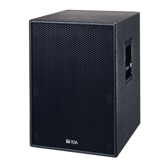
12. SPECIFICATIONS [SR-F09] Enclosure Bass-reflex type Power Handling Capacity Continuous pink noise: 200 W Continuous program: 600 W Rated Impedance 8 Ω Sensitivity 100 dB (1 W, 1 m) Frequency Response 70 Hz to 20 kHz* Crossover Frequency 1 kHz* Speaker Component Low frequency: 30 cm cone-type High frequency: C D horn (60° horizontal x 40° vertical) fitted with compression driver Input Connector Neutrik NL4MP x 2 and M5 screw terminal, distance between barriers: 12.2 mm Finish Enclosure: Plywood, black, paint Front grille: Steel plate, black, acrylic paint Dimensions 390 (w) x 619 (h) x 364 (d) mm Weight 35 kg Accessories Label ..