Advertisement
Quick Links
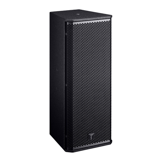
SPEAKER SYSTEM
INSTRUCTION MANUAL
INSTRUCTION MANUAL
Update history
TOA1912
No.833-72-521-10
TABLE OF CONTENTS
TABLE OF CONTENTS ................................................................................................................................. 1
GENERAL DESCRIPTION ............................................................................................................................ 1
SPECIFICATIONS ......................................................................................................................................... 1
SCHEMATIC DIAGRAM ................................................................................................................................ 2
WIRING DIAGRAM ........................................................................................................................................ 3
MOUNTING DIAGRAM AND PARTS LIST .................................................................................................... 4
•NETWORK PCB ASSY. ............................................................................................................................ 4
EXPLODED VIEW AND PARTS LISTS ......................................................................................................... 5
GENERAL DESCRIPTION
The SR-F04 is a speaker system designed for permanent and temporary indoor installations, featuring
high power handling capacity and high quality sound.
SPECIFICATIONS
System Type
2-way, Passive type, Bass-re ex type
Power Handling Capacity
Continuous pink noise: 80 W, Continuous program: 240 W
Rated Impedance
8Ω
Sensitivity
88 dB (1 W, 1 m)
Frequency Response
80 Hz to 20 kHz
Crossover Frequency
3 kHz
Directivity Angle
70° Conical
Speaker Component
Low frequency: 10 cm (4") cone-type x 2
High frequency: Compression driver tted with CD horn
Input Connector
Neutrik NL4MP x 2, M4 screw terminal, distance between barriers: 11 mm (0.43")
Finish
Enclosure:
Birch plywood, black, polyurea coating
Grille:
Steel plate, black, 40% glossy, paint
Dimensions
165 (w) x 400 (h) x 177 (d) mm (6.5" x 15.75" x 6.97")
Weight
5.8 kg (12.79 lb)
Option
Speaker mounting bracket:
Ceiling mount bracket:
Speaker wall mount bracket: HY-WM04, HY-W0801
Speaker stand adapter:
Speaker stand:
MODEL SR-F04
HY-B0801, HY-UH04, HY-UV04
HY-C0801
HY-ST04
ST-34B
1
Advertisement

Related Manuals for Toa SR-F04


Summary of Contents for Toa SR-F04
-
Page 1: Table Of Contents
SR-F04 •NETWORK PCB ASSY..........................4 EXPLODED VIEW AND PARTS LISTS ......................5 GENERAL DESCRIPTION The SR-F04 is a speaker system designed for permanent and temporary indoor installations, featuring high power handling capacity and high quality sound. SPECIFICATIONS INSTRUCTION MANUAL... -
Page 2: Schematic Diagram
MODEL SR-F04 SCHEMATIC DIAGRAM Network PCB assy. SCHEMATIC DIAGRAM... -
Page 3: Wiring Diagram
MODEL SR-F04 WIRING DIAGRAM Woofer BST-296 – Soldering Screw terminal – BST-296 – Tweeter 2– 2– – 1– 1– Black Speaker terminal Network PCB Assy. T5343 Back side of Terminal Plate · HARNESS LIST Ref.No. Part Code Description 123-29-257-90 HARNESS,U1007#16(100)H/187FST-... -
Page 4: Mounting Diagram And Parts List
MODEL SR-F04 MOUNTING DIAGRAM AND PARTS LIST •NETWORK PCB ASSY. (Part Code : 770-10-00554-00 ) Apply silicone sealant to the shaded area. · PARTS LIST Designator Part Code Description 123-16-498-60 CONNECTOR, 6P, PCB MOUNT 123-16-496-80 CONNECTOR, 4P, PCB MOUNT 123-16-494-80 CONNECTOR, 2P, PCB MOUNT L2–... -
Page 5: Exploded View And Parts Lists
MODEL SR-F04 EXPLODED VIEW AND PARTS LISTS Check if the fuse has blown when replacing the woofer unit. Ref.No. Part Code Description 170-20-00706-00 PUNCHEDNET, SRF04 W/FILTTER 131-03-00389-00 SRF04 BRAND-MARK 105-02-507-20 SPACER, BRAND MARK SF60 102-01-00666-00 BRACKET, SRF04 NET-ANGLE 770-20-00087-00 SPEAKER UNIT. BST296 00293 170-30-01297-00 ES01KS HORN 770-10-00554-00 PCB ASSY.