Table of Contents
Advertisement
Quick Links
Advertisement
Table of Contents

Related Manuals for Toa SR-F1D


Summary of Contents for Toa SR-F1D
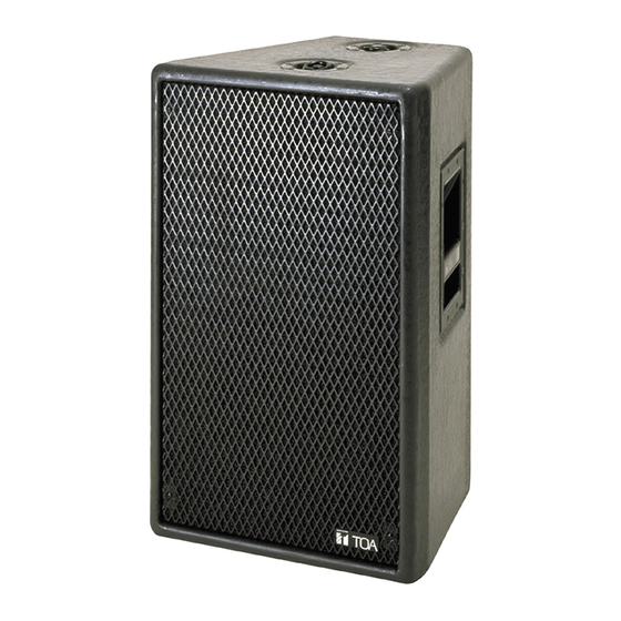
- Page 1 OPERATING INSTRUCTIONS SPEAKER SYSTEM SR-F1D SUBWOOFER SYSTEM SR-L1B SR-F1D SR-L1B Please follow the instructions in this manual to obtain the optimum results from this unit. We also recommend that you keep this manual handy for future reference.
-
Page 2: Table Of Contents
4. INSTALLING THE SR-F1D ON THE SR-L1B ........... 5 5. FLYING (SR-F1D ONLY) 5.1. Direct Suspension Using the SR-F1D's Flying Hardware ......... 6 5.2. Suspension Using Optional Flying Hardware 5.2.1. SR-F1D speaker flying hardware system ..........7 5.2.2. Flying precautions ................... 8 5.2.3. -
Page 3: Safety Precautions
1. SAFETY PRECAUTIONS • Be sure to read the instructions in this section carefully before use. • Make sure to observe the instructions in this manual as the conventions of safety symbols and messages regarded as very important precautions are included. •... - Page 4 • Do not stand or sit on, nor hang down from the unit CAUTION as this may cause it to fall down or drop, resulting in personal injury and/or property damage. • Have the unit checked periodically by the shop When Installing the Unit from where it was purchased.
-
Page 5: General Description
• Because the sides of the SR-F1D's enclosure are angled at 15°, when multiple speakers are arranged side- by-side, they can be oriented in a radial array, which helps suppress mutual interference at high frequencies. -
Page 6: Flying (Sr-F1D Only)
5. FLYING (SR-F1D ONLY) Two flying methods can be performed: 1) direct suspension using the SR-F1D's flying hardware (refer to the figures below), and 2) suspension using optional flying hardware (refer to p. 7). WARNING • Be sure to refer flying construction work to the dealer from whom the speaker was purchased. -
Page 7: Suspension Using Optional Flying Hardware
The speaker flying hardware system is manufactured by ATM FLY-WARE (ATM GROUP, Inc.) of the United States for use with TOA's SR-F1D speaker. The flying system permits various speaker array configurations to be constructed quickly and safely without using special components. -
Page 8: Flying Precautions
5.2.2. Flying precautions • Confirm the following points before installation. 1. Load on each flying hardware component does not exceed its allowable load. 2. All quick release pins (2.5QRP) are fully inserted into other components and locked. 3. All components used in suspension (i.e. enclosures, individual flying hardwares, clamps, connectors, and suspension devices) are free from any deformation, crack and corrosion. -
Page 9: Speaker Stand For Sr-F1D
6. SPEAKER STAND FOR SR-F1D The speaker stand manufactured by Köning & Meyer GMBH (K & M) of Germany is made available for use with TOA's SR-F1D speaker. The speaker stand consists of two main sections, which are sold separately. -
Page 10: Input Connector
8. CONNECTION DIAGRAMS • It is recommended that TOA's IP-600D Power Amplifier be connected and used. • The DP-0206 Digital Processor's compressor has been set based on a power amplifier gain of "20 dB."... -
Page 11: Processor Settings
9. PROCESSOR SETTINGS Set the following parameters – for the DP-0206 Digital Processor. Perform settings for either the "flat phase type" (p. 12) or "minimum delay type" (p. 13) depending on the application. Note Refer to the DP-0206 Software Instruction Manual for setting instructions. -
Page 12: Flat Phase Type
Ratio 4 : 1 Low Shelving 6 dB Sync Gain Polarity Delay Attack Inverse 0.667 Release X-over Filter Comp. OUTPUT 2 SR-F1D Type Freq. Type Freq. Gain Thresh 12 dB BW –1.5 4.318 Ratio 2 : 1 24 dB BS –1.5... -
Page 13: Minimum Delay Type
Ratio 4 : 1 Low Shelving 6 dB Sync Gain Polarity Delay Attack Inverse Release X-over Filter Comp. OUTPUT 2 SR-F1D Type Freq. Type Freq. Gain Thresh –2.0 4.318 12 dB BW Ratio 2 : 1 24 dB BS –2.0 4.318... -
Page 14: Characteristic Diagrams
10. CHARACTERISTIC DIAGRAMS Note: Referenced to 200 Hz in the SR-F1D's LOW band, 1 W 1 m 10.1. SR-F1D + SR-L1B (when DP-0206 is used) 10.1.1. Flat phase type Frequency Characteristics [dB] SR-F1D + SR-L1B SR-L1B SR-F1D LOW SR-F1D HIGH... -
Page 15: Sr-F1D (When Dp-0206 Is Used)
10.2. SR-F1D (when DP-0206 is used) [Polar pattern] Horizontal Vertical Woofer Horn 0° 0° 30° 330° 30° 330° –10 –10 60° 300° 60° 300° –20 –20 –30 –30 –40 –40 270° 270° 90° 90° –40 –40 –30 –30 –20 –20 120°... -
Page 16: Specifications
12. SPECIFICATIONS [SR-F1D] Enclosure Bass reflex type Power Handling Continuous pink noise: 120 W (Low frequency)* , 80 W (High frequency)* Capacity Continuous program: 360 W (Low frequency), 240 W (High frequency) Low frequency: 8 Ω, High frequency: 16 Ω...