Table of Contents
Advertisement
Quick Links
SPEAKER SYSTEM
SUBWOOFER SYSTEM
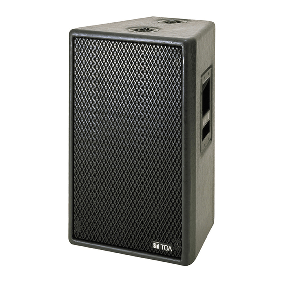
SR-F1D
TABLE OF CONTENTS
1. SAFETY PRECAUTIONS ............................. 2
2. GENERAL DESCRIPTION ........................... 4
3. FEATURES ................................................... 4
5. FLYING (SR-F1D ONLY) .............................. 5
6. SPEAKER STAND FOR SR-F1D ................ 6
7. INPUT CONNECTOR .................................... 7
8. CONNECTION DIAGRAMS ......................... 7
Thank you for purchasing TOA's Speaker System.
Please carefully follow the instructions in this manual to ensure long, trouble-free use of your equipment.
........................... 7
OPERATING INSTRUCTIONS
SR-L1B
9. DIGITAL PROCESSOR SETTINGS ............. 8
9.1. Flat Phase Type ...................................... 8
9.2. Minimum Delay Type .............................. 9
10. CHARACTERISTIC DIAGRAMS ............. 10
10.1. SR-F1D + SR-L1B .............................. 10
10.2. SR-F1D ............................................... 11
11. DIMENSIONAL DIAGRAMS .................... 11
12. SPECIFICATIONS .................................... 12
) .... 7
SR-F1D
SR-L1B
Advertisement
Table of Contents

Related Manuals for Toa SR-F1D


Summary of Contents for Toa SR-F1D
-
Page 1: Table Of Contents
9.2. Minimum Delay Type ......9 3. FEATURES ........... 4 10. CHARACTERISTIC DIAGRAMS ..... 10 4. INSTALLING THE SR-F1D ON THE SR-L1B ... 4 10.1. SR-F1D + SR-L1B ......10 5. FLYING (SR-F1D ONLY) ......5 10.2. SR-F1D ..........11 6. -
Page 2: Safety Precautions
1. SAFETY PRECAUTIONS • Before installation or use, be sure to carefully read all the instructions in this section for correct and safe operation. • Be sure to follow all the precautionary instructions in this section, which contain important warnings and/or cautions regarding safety. • After reading, keep this manual handy for future reference. Safety Symbol and Message Conventions Safety symbols and messages described below are used in this manual to prevent bodily injury and property damage which could result from mishandling. Before operating your product, read this manual first and understand the safety symbols and messages so you are thoroughly aware of the potential safety hazards. - Page 3 CAUTION • Do not stand or sit on, nor hang down from the speaker as this may cause it to fall down or drop, resulting in personal injury and/or property damage. When Installing the Unit • Have the speaker checked periodically by the shop from where it was purchased. Failure to do so may • When unpacking or moving the speaker, be sure result in corrosion or damage to the speaker that to handle it with two or more persons.
-
Page 4: General Description
• Neutrik NL4MPR input connectors ensure quick and accurate system field installations. • The SR-F1D features flying hardware (ring/stud pan fittings) installed on its top and bottom. The bottom surface is also equipped with built-in nuts for mounting on an optional stand. • Because the sides of the SR-F1D's enclosure are angled at 15°, when multiple speakers are arranged side- by-side, they can be oriented in a radial array, which helps suppress mutual interference at high frequencies. -
Page 5: Flying (Sr-F1D Only)
5. FLYING (SR-F1D ONLY) WARNING • Be sure to refer flying construction work to the dealer from whom the speaker was purchased. • Avoid flying methods other than those described in this section. Otherwise, the suspension wires or belts may be off or snap and the speaker may fall off, causing personal injury. Shown below are the general flying methods: SR-F1D's flying hardware • Use the pan fitting rings attached to the speaker’s top and/or bottom. • Provide at least two suspension points on each speaker’s top. • The maximum number of speakers that can be suspended vertically is three. -
Page 6: Speaker Stand For Sr-F1D
6. SPEAKER STAND FOR SR-F1D The speaker stand manufactured by Köning & Meyer GmbH (K & M) of Germany is made available for use with TOA's SR-F1D speaker. The speaker stand consists of two main sections, which are sold separately. Stand: Model 213 Stand bracket: Model 195/8 Step 1. Extend the stand's legs. Loosen the tripod fixing screw and open the tripod legs outward so that the stays become level. SR-F1D Then, tighten the fixing screw. WARNING Fully extend the stand’s tripod legs and place the stand on a stable surface. -
Page 7: Input Connector
* The "left" and the "right" are the positions of woofer units as viewed from the front. 8. CONNECTION DIAGRAMS 8.1. Single System (SR-F1D) HIGH Mixer/Preamplifier Digital processor Power amplifier SR-F1D 8.2. Combination System (SR-F1D and SR-L1B) Digital processor HIGH SR-F1D Mixer/Preamplifier Power amplifier SUB-LOW Power amplifier SR-L1B... -
Page 8: Digital Processor Settings
Low Shelving Sync SR-L1B INVERSE 0.667 Attack (ms) Release (ms) 12 dB Butterworth Thresh (dB) 24 dB Bessel –1.5 4.318 Ratio SR-F1D NORMAL –1.5 4.318 Sync 1.80 k –12.0 9.889 Attack (ms) 2.00 k –2.0 4.608 Release (ms) 12 dB Butterworth Thresh (dB) 13.6 k... -
Page 9: Minimum Delay Type
Ratio SR-L1B INVERSE Low Shelving Sync Attack (ms) Release (ms) 12 dB Butterworth Thresh (dB) 24 dB Bessel Ratio –2.0 4.318 Sync SR-F1D NORMAL –2.0 4.318 Attack (ms) –3.0 8.615 Release (ms) 1.80 k –12.0 9.889 2.00 k –2.0 4.608... -
Page 10: Characteristic Diagrams
10. CHARACTERISTIC DIAGRAMS Note: Referenced to 200 Hz in the SR-F1D's LOW band, 1 W 1 m 10.1. SR-F1D + SR-L1B (When recommended parameters are applied by the digital processor) 10.1.1. Flat phase type Frequency Characteristics [dB] SR-F1D + SR-L1B SR-L1B SR-F1D LOW SR-F1D HIGH 10 k 20 k [Hz] Frequency Phase Characteristics [deg] –90... -
Page 11: Sr-F1D
10.2. SR-F1D (When recommended parameters are applied by the digital processor) [Polar pattern] Horizontal Vertical Woofer Horn –10 –10 –20 –20 –30 –30 –40 –40 –40 –40 –30 –30 –20 –20 –10 –10 1,000 Hz 2,000 Hz 4,000 Hz 8,000 Hz 11. -
Page 12: Specifications
12. SPECIFICATIONS [SR-F1D] Enclosure Bass-reflex type Power Handling Continuous pink noise: 120 W (Low frequency) , 80 W (High frequency) Capacity Continuous program: 360 W (Low frequency), 240 W (High frequency) Rated Impedance Low frequency: 8 Ω, High frequency: 16 Ω Sensitivity Low frequency: 98 dB (1 W, 1 m), High frequency: 110 dB (1 W, 1 m) Frequency Response 70 Hz– 20 kHz Crossover Frequency 1 kHz Speaker Component Low frequency: One 30 cm dia. cone-type High frequency: CD horn (60° horizontal by 40° vertical) plus compression driver Input Connector NEUTRIK NL4MPR Finish Enclosure: Urethane coating, gray Front grill: Black, paint Dimensions 390 (w) x 619 (h) x 364 (d) mm...