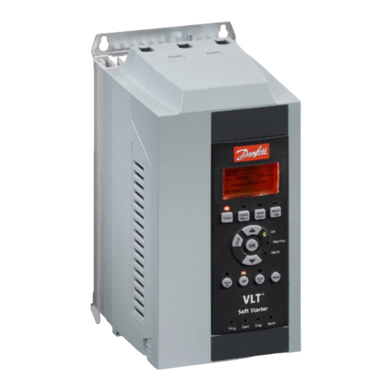
Danfoss VLT MCD 201 Installation Manual
Profinet module
Hide thumbs
Also See for VLT MCD 201:
- Design manual (24 pages) ,
- Pocket manual (64 pages) ,
- Installation manual (36 pages)
Summary of Contents for Danfoss VLT MCD 201
- Page 1 ENGINEERING TOMORROW Installation Guide PROFINET Module ® Compact Starter MCD 201/MCD 202 ® Soft Starter MCD 500 vlt-drives.danfoss.com...
-
Page 3: Table Of Contents
7.1 Ensuring Safe and Successful Control 7.2 Control Commands (Write Only) 7.3 Status Commands (Read Only) 7.3.1 Bytes 0–1: Control Status 7.3.2 Bytes 2–3: Starter State 7.3.3 Bytes 4–5: Trip Code 7.3.4 Bytes 6–7: Motor Current MG17P102 Danfoss A/S © 11/2017 All rights reserved. - Page 4 7.4 Parameter Management (Read/Write) 7.4.1 Output 7.4.2 Input 7.5 Trip Codes 7.5.1 Internal Fault X 8 Network Design 8.1 Star Topology 8.2 Line Topology 8.3 Ring Topology 8.4 Combined Topologies 9 Specifications Index Danfoss A/S © 11/2017 All rights reserved. MG17P102...
-
Page 5: Introduction
Parameter name. control voltage. • Parameter group name. • The PROFINET Module allows a Danfoss soft starter to Parameter option. connect to an Ethernet network and be controlled or monitored using an Ethernet communication model. MG17P102 Danfoss A/S © 11/2017 All rights reserved. -
Page 6: Safety
Disconnect the soft starter from mains. • Completely wire and assemble the soft starter, motor, and any driven equipment before connecting the soft starter to AC mains, DC supply, or load sharing. Danfoss A/S © 11/2017 All rights reserved. MG17P102... - Page 7 Responsibility or liability is never accepted for direct, indirect, or consequential damage resulting from the use or application of this equipment. MG17P102 Danfoss A/S © 11/2017 All rights reserved.
-
Page 8: Installation
Connect Ethernet port 1 or port 2 on the PROFINET Module to the network. Apply control power to the soft starter. Illustration 3.2 Removing the PROFINET Module Illustration 3.1 Installing the PROFINET Module Danfoss A/S © 11/2017 All rights reserved. MG17P102... -
Page 9: Connection
MCD 201/202 MCD 500 A1, N2: Stop input (Auto-on mode) 17, 18: Stop input 25, 18: Reset input PROFINET Module PROFINET Module RJ45 Ethernet ports RJ45 Ethernet ports Table 4.1 Connection Diagrams MG17P102 Danfoss A/S © 11/2017 All rights reserved. -
Page 10: Network Connection
The MAC address is fixed within the device and is printed on a label on the front of the module. 3-phase supply Ethernet cable ProfiNet MAC: 00-02-A2-25-DC-B3 Illustration 4.1 Correct Running of Ethernet Cables Illustration 4.2 MAC ID Location Danfoss A/S © 11/2017 All rights reserved. MG17P102... -
Page 11: Device Configuration
Apply control power to the soft starter. temporary. Start the Ethernet Device Configuration Tool. In Options ⇒ Protocols, select DCP and deselect NetIdent. Illustration 5.1 Starting the Tool Illustration 5.3 Setting a Static IP Address MG17P102 Danfoss A/S © 11/2017 All rights reserved. - Page 12 Device Configuration PROFINET Module To configure a device name, click Configure, then select Device Name. Illustration 5.4 Configuring a Device Name Danfoss A/S © 11/2017 All rights reserved. MG17P102...
-
Page 13: Operation
PROFINET standard. For successful Import the latest GSDML file into the master configuration operation, the controller must also support all functions tool. The file is available from drives.danfoss.com/ and interfaces described in this manual. services/pc-tools. 6.1 Device Classification... -
Page 14: Packet Structures
1 = Auto On. 1 = Ramping (starting or stopping). 1 = Ready. 1 = Starting, running, or stopping. 1 = Tripped. 1 = Warning. 12–15 Reserved. Table 7.2 Description of Bytes 0–1 Danfoss A/S © 11/2017 All rights reserved. MG17P102... -
Page 15: Bytes 2-3: Starter State
Product type code 2 = Reset. 4 = MCD 200 3 = Input A. 7 = MCD 500 4–15 = Reserved. 12–13 Device details 48–49 Trip code 0–15 See chapter 7.5 Trip Codes. MG17P102 Danfoss A/S © 11/2017 All rights reserved. -
Page 16: Parameter Management (Read/Write)
✓ Bypass fail (bypass contactor) Table 7.8 Structure of Master to Slave Output Bytes ✓ L1 phase loss ✓ L2 phase loss ✓ L3 phase loss ✓ L1-T1 short-circuited Danfoss A/S © 11/2017 All rights reserved. MG17P102... -
Page 17: Internal Fault
Firing Fail Px 80–82 VZC Fail Px Low Control Volts 84–98 Internal fault x Contact the local supplier with the fault code (X). Table 7.11 Internal Fault Code Associated with Trip Code 17 MG17P102 Danfoss A/S © 11/2017 All rights reserved. -
Page 18: Network Design
Illustration 8.3 Ring Network Topology Illustration 8.2 Line Network Topology NOTICE The network switch must support loss of line detection. Danfoss A/S © 11/2017 All rights reserved. MG17P102... -
Page 19: Combined Topologies
Network Design Installation Guide 8.4 Combined Topologies A single network can include both star and line components. Illustration 8.4 Combined Star/Line Network Topology MG17P102 Danfoss A/S © 11/2017 All rights reserved. -
Page 20: Specifications
10 Mbps, 100 Mbps (auto-detect) Full duplex Auto crossover Power Consumption (steady state, maximum) 35 mA at 24 V DC Reverse polarity protected Galvanically isolated Certification IEC 60947-4-2 IEC 60947-4-2 PROFIBUS & PROFINET International Danfoss A/S © 11/2017 All rights reserved. MG17P102... -
Page 21: Index
Terminals A1......................7 N2......................7 Heat sink..................... 4 Inputs Unintended start..................4 Remote....................4 Installing the PROFINET module............6 Intended use..................... 3 Weight...................... 18 Internal fault code................15 IP address.................... 8, 18 MG17P102 Danfoss A/S © 11/2017 All rights reserved. - Page 22 Danfoss can accept no responsibility for possible errors in catalogues, brochures and other printed material. Danfoss reserves the right to alter its products without notice. This also applies to products already on order provided that such alterations can be made without subsequential changes being necessary in specifications already agreed. All trademarks in this material are property of the respective companies.


