Omron NA5-12W series Hardware User Manual
Programmable terminal na series
Hide thumbs
Also See for NA5-12W series:
- Practices manual (65 pages) ,
- Notice (2 pages) ,
- Practices manual (65 pages)

Related Manuals for Omron NA5-12W series


Summary of Contents for Omron NA5-12W series
- Page 1 Programmable Terminal NA-series Hardware User’s Manual NA5-15101 NA5-12101 NA5-9001 NA5-7001 V117-E1-08...
- Page 2 No patent liability is assumed with respect to the use of the information contained herein. Moreover, because OMRON is constantly striving to improve its high-quality products, the information contained in this manual is subject to change without notice. Every precaution has been taken in the preparation of this manual. Neverthe- less, OMRON assumes no responsibility for errors or omissions.
-
Page 3: Introduction
Introduction Introduction Thank you for purchasing an NA-series Programmable Terminal. This manual contains information that is necessary to use the NA-series Programmable Terminal. Please read this manual and make sure you understand the functionality and performance of the NA-series Programmable Terminal before you attempt to use it in a control system. Keep this manual in a safe place where it will be available for reference during operation. -
Page 4: Relevant Manuals
Relevant Manuals Relevant Manuals The basic information required to use an NA-series PT is provided in the following three manuals. • NA-series Programmable Terminal Hardware User’s Manual (Cat. No. V117) • NA-series Programmable Terminal Software User’s Manual (Cat. No. V118) •... -
Page 5: Manual Structure
Manual Structure Manual Structure Page Structure and Markings The following page structure is used in this manual. Level 1 heading 3 Installation and Wiring Level 2 heading Installing NA-series PTs Level 3 heading Level 2 heading Give the current headings. Level 3 heading 3-3-1 Installation in a Control Panel... - Page 6 Manual Structure Special Information Special information in this manual is classified as follows: Precautions for Safe Use Precautions on what to do and what not to do to ensure safe usage of the product. Precautions for Correct Use Indicates precautions on what to do and what not to do to ensure proper operation and perfor- mance.
-
Page 7: Sections In This Manual
Sections in this Manual Sections in this Manual Introduction to the NA-series Programmable Terminals Configuration Units Installation and Wiring System Program Troubleshooting Maintenance Appendices Index NA-series Programmable Terminal Hardware User’s Manual (V117) - Page 8 Sections in this Manual NA-series Programmable Terminal Hardware User’s Manual (V117)
-
Page 9: Table Of Contents
CONTENTS CONTENTS Introduction ......................1 Relevant Manuals..................... 2 Manual Structure...................... 3 Sections in this Manual ................... 5 Terms and Conditions Agreement ................11 Safety Precautions....................13 Precautions for Safe Use ..................15 Precautions for Correct Use ................. 18 Regulations and Standards .................. 19 Conformance to Shipbuilding Standards ............ - Page 10 CONTENTS USB Memory Devices......................2-11 2-3-1 Models and Specifications ......................2-11 2-3-2 Applications..........................2-11 2-3-3 Installing and Removing......................2-11 Support Software......................... 2-13 2-4-1 Connection Methods ......................... 2-13 Section 3 Installation and Wiring Processing at Power ON and Power OFF ................3-2 3-1-1 Power ON Operation........................
- Page 11 CONTENTS Section 5 Troubleshooting Operation after an Error ......................5-2 5-1-1 Checking NA Unit Status ......................5-2 5-1-2 Fatal Errors in the NA Unit......................5-2 5-1-3 Nonfatal Errors in the NA Unit ....................5-3 Troubleshooting ........................5-4 5-2-1 Confirming NA Unit Operation ....................5-4 5-2-2 Correcting Fatal Errors in the NA Unit ..................
- Page 12 CONTENTS NA-series Programmable Terminal Hardware User’s Manual (V117)
-
Page 13: Terms And Conditions Agreement
Omron’s exclusive warranty is that the Products will be free from defects in materials and workman- ship for a period of twelve months from the date of sale by Omron (or such other period expressed in writing by Omron). Omron disclaims all other warranties, express or implied. - Page 14 Disclaimers Performance Data Data presented in Omron Company websites, catalogs and other materials is provided as a guide for the user in determining suitability and does not constitute a warranty. It may represent the result of Omron’s test conditions, and the user must correlate it to actual application requirements. Actual perfor- mance is subject to the Omron’s Warranty and Limitations of Liability.
-
Page 15: Safety Precautions
Safety Precautions Safety Precautions Definition of Precautionary Information The following notation is used in this manual to provide precautions required to ensure safe usage of the NA-series Programmable Terminal. The safety precautions that are provided are extremely impor- tant to safety. Always read and heed the information provided in all safety precautions. The following notation is used. - Page 16 Safety Precautions Warnings WARNING Do not attempt to take the NA Unit apart and do not touch the product inside while the power is being supplied. Otherwise it may result in electric shock. Always ensure that the personnel in charge confirm that installation, inspection, and maintenance were properly performed for the NA Unit.
- Page 17 Precautions for Safe Use Precautions for Safe Use • When unpacking the NA Unit, check carefully for any external scratches or other damages. Also, shake the NA Unit gently and check for any abnormal sound. • The NA Unit must be installed in a control panel. •...
- Page 18 Precautions for Safe Use • Disconnecting the cable between a support tool and the NA Unit. • Do not connect an AC power supply to the DC power terminals. • Do not perform a dielectric strength test. • Use a DC power with a slight voltage fluctuation and that will provide a stable output even if the input is momentarily interrupted for 10 ms.
- Page 19 Precautions for Safe Use • To use numeric input functions safely, always make maximum and minimum limit settings. • Do not press the touch panel with a force greater than 30 N. • Do not use hard or pointed objects to operate or scrub the screen, otherwise the surface of the screen may be damaged.
-
Page 20: Precautions For Correct Use
Precautions for Correct Use Precautions for Correct Use Do not install or store the NA Unit in any of the following locations: • Locations subject to severe changes in temperature • Locations subject to temperatures or humidity outside the range specified in the specifications •... -
Page 21: Regulations And Standards
Concepts EMC Directive OMRON devices that comply with EC Directives also conform to the related EMC standards so that they can be more easily built into other devices or the overall machine. The actual products have been checked for conformity to EMC standards.* Whether the products conform to the standards in the system used by the customer, however, must be checked by the customer. - Page 22 Regulations and Standards Conformance to KC Standards Observe the following precaution if you use NA-series PTs in Korea. Class A Device (Broadcasting Communications Device for Business Use) This device obtained EMC registration for office use (Class A), and it is intended to be used in places other than homes.
-
Page 23: Conformance To Shipbuilding Standards
The NA-series Programmable Terminals comply with shipping standards. Application conditions are set for compliance for individual shipping standards, and it may not be possible to use the product in some installation locations. Contact an OMRON sales representative before using the product. International Shipping Standards... - Page 24 Conformance to Shipbuilding Standards Certification Zones for Shipping Standards b. Bridge Air conditioning a. Deck No air conditioning Devices on deck or bridge Devices not on deck or bridge Ocean e. Boiler room c. Depends on ship type d. Engine room Air conditioning Emergency power supply devices on No air conditioning...
-
Page 25: Related Manuals
Related Manuals Related Manuals The following manuals are related to the NA-series PTs. Use these manuals for reference. Manual name Cat. No. Models Applications Description NA-series Program- V117 NA5-W Learning the speci- Information is provided on NA-series mable Terminal Hard- fications and set- PT specifications, part names, instal- ware User’s Manual... - Page 26 Related Manuals Manual name Cat. No. Models Applications Description NJ-series CPU Unit W500 NJ501- Learning the basic An introduction to the entire Hardware User’s specifications of NJ-series system is provided along NJ301- Manual the NJ-series CPU with the following information on a NJ101-...
- Page 27 Related Manuals Manual name Cat. No. Models Applications Description CS/CJ/NSJ Series W340 CS1□-CPU-- Learning detailed Instructions are described in detail. Instructions Refer- information on pro- CJ1□-CPU-- When programming, use this manual ence Manual gramming instruc- together with the Operation Manual CJ2H-CPU--...
- Page 28 Related Manuals Manual name Cat. No. Models Applications Description Ethernet Units Oper- W420 CS1W-ETN21 Learning how to Information is provided on the Ether- ation Manual Con- use an Ethernet net Units. CJ1W-ETN21 struction of Networks Unit. Information is provided on the basic setup and FINS communications.
- Page 29 Related Manuals Manual name Cat. No. Models Applications Description NY-Series IPC W556 NY512-1 Learning the basic An introduction to the entire NY-series system is provided along Machine Controller specifications of Industrial Box PC the NY-series with the following information on the Hardware User's Industrial Box PCs, Industrial Box PC.
- Page 30 Related Manuals Manual name Cat. No. Models Applications Description NX-series NX1P2 W579 NX1P2- Learning about the Of the functions for an NX1P2 CPU Unit, the following information is pro- CPU Unit Built-in I/O details of functions and Option Board only for an vided.
-
Page 31: Terminology
Term Description A general term for interface devices that indicates both hardware and software elements. In this manual, “HMI” refers to an OMRON Sysmac-brand product unless otherwise specified. The hardware elements of the HMI. NA Series The NA Series of Programmable Terminals and peripheral devices. -
Page 32: Revision History
Revision History Revision History A manual revision code appears as a suffix to the catalog number on the front and back covers of the manual. V117-E1-08 Cat. No. Revision code Revision code Date Revised content June 2014 Original production October 2014 Made revisions accompanying version upgrade. -
Page 33: Introduction To The Na-Series Programmable Terminals
Introduction to the NA-series Pro- grammable Terminals This section describes the features, basic system configuration, specifications, and overall operating procedure of the NA-series Programmable Terminals. 1-1 NA-series Programmable Terminals ......1-2 1-1-1 Features . -
Page 34: Na-Series Programmable Terminals
They provide all of the functions of traditional programmable terminals with a clearer, easy-to-use interface. OMRON offers the new Sysmac Series of control devices designed with unified communications speci- fications and user interface specifications. The NA-series Programmable Terminals are Sysmac devices that you can use together with the NJ/NX/NY-series Machine Automation Controllers and the Sysmac Studio Automation Software to achieve optimum functionality and ease of operation. - Page 35 1 Introduction to the NA-series Programmable Terminals Standard-feature SD Memory Card Slot You can use an SD Memory Card inserted in the NA Unit to automatically transfer the project you created on the Sysmac Studio to the NA Unit, to update the system program in the NA Unit, or to save the log data from the NA Unit.
-
Page 36: System Configurations
1 Introduction to the NA-series Programmable Terminals System Configurations The section describes the system configurations of an NA-series PT. 1-2-1 Connecting to the Support Software You can connect the Sysmac Studio to a USB port on the NA Unit with a commercially available USB cable. -
Page 37: Available Products
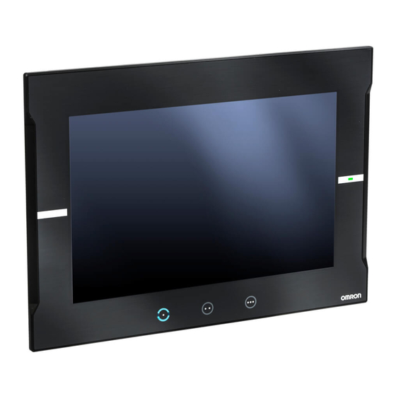
1 Introduction to the NA-series Programmable Terminals Available Products This section provides tables of the NA Units and optional products. Refer to 1-4 Specifications on page 1-7 for detailed specifications. 1-3-1 NA Units Case Display Data Power con- Model Weight Appearance Color panel... -
Page 38: Other Optional Products
1 Introduction to the NA-series Programmable Terminals 1-3-3 Other Optional Products SD Memory Cards Model Appearance Capacity HMC-SD291 2 GB HMC-SD491 4 GB USB Memory Devices Model Appearance Capacity FZ-MEM2G 2 GB FZ-MEM8G 8 GB Other Products Name Model Appearance Specifications Battery Set CJ1W-BAT01... -
Page 39: Specifications
1.3 kg max. Front-panel controls: IP65 oil-proof type, UL Type 4X (at initial state) Degree of pro- To reinstall the NA Unit in a panel, contact your OMRON representative for replacement of tection the rubber packing. Battery life: 5 years at 25°C The RTC will be backed up for 5 days after the battery runs low. - Page 40 1 Introduction to the NA-series Programmable Terminals Specification Item NA5-15W NA5-12W NA5-9W NA5-7W NA5-15U NA5-12U NA5-9U NA5-7U UL 508/CSA standard C22.2 No.142 EMC Directive (2004/108/EC) EN 61131-2:2007 Shipbuilding standards LR, DNV, and NK International IP65 oil-proof, UL Type 4X (front panel only) standards ANSI 12.12.01 Class 1 Division 2/CSA standard C22.2 No.
- Page 41 Temperature [°C] *4. Check with your OMRON representative or refer to the following OMRON website for the latest information on the applicable standards for each model: www.ia.omron.com. *5. Use power supply Class 2 to conform to UL Standards.
-
Page 42: Performance Specifications
NA5-9W NA5-7W *2. The backlight can be replaced at an OMRON maintenance base. *3. This is the estimated time before brightness is reduced by half at room temperature and humidity. The life expectancy is drastically shortened if PT is used at high temperatures. -
Page 43: External Interfaces
1 Introduction to the NA-series Programmable Terminals External Interfaces Item Specifications (Same for all models.) Ethernet ports Applications Port 1: Connecting to anything other than the Sysmac Studio, e.g., device connections and VNC clients Port 2: Connecting to the Sysmac Studio in addition to the applications of port 1. - Page 44 1 Introduction to the NA-series Programmable Terminals 1 - 12 NA-series Programmable Terminal Hardware User’s Manual (V117)
-
Page 45: Configuration Units
Configuration Units This section describes the basic system configuration and devices used for NA-series Programmable Terminals. 2-1 NA Units ........... . . 2-2 2-1-1 Components and Functions . -
Page 46: Na Units
2 Configuration Units NA Units This section describes the names and functions of NA Unit parts and installation methods and provides other information. 2-1-1 Components and Functions Front Panel RUN indicator Display F1 Key F2 Key F3 Key Function keys Name Description ... - Page 47 2 Configuration Units Precautions for Safe Use • Do not press the touch panel with a force greater than 30 N. • The deterioration over time may cause the touch points to move on the touch panel. Cali- brate the touch panel periodically. •...
-
Page 48: Back Panel
2 Configuration Units Back Panel • Back Panel (m) ID information label (a) Battery cover (b) Expansion Unit connector (for future expansion) • Bottom Panel (d) Ethernet ports (e) Serial port (for future expansion) (c) SD Memory (f) USB host port Card connector (g) USB slave port (l) DC input... - Page 49 2 Configuration Units Name Description Battery cover Open this cover to replace the Battery. For future expansion. Expansion Unit connector SD Memory Card connector Insert an SD Memory Card here. Ethernet port 1 Connect a device other than the Sysmac Studio. Ethernet port 2 Connect mainly the Sysmac Studio.
- Page 50 2 Configuration Units Power Supply Connector Pin Arrangement Pin No. Pin No. Signal name Name +24 V +24-V input Functional ground Reset Switch Use a precision screwdriver or similar device with a diameter of less than 2.4 mm. The reset switch performs the same function as cycling the power supply.
- Page 51 2 Configuration Units • Connecting Devices That Support IEEE 802.3i (10BASE-T) or IEEE 802.3u (100BASE-TX) Pin No. Signal name Name Twisted-pair output (differential output) Twisted-pair output (differential output) Twisted-pair input (differential input) BI D+ Protection circuit BI D- Protection circuit Twisted-pair input (differential input) BI D+ Protection circuit...
- Page 52 Give the MAC addresses of the Ethernet ports. Lot number Gives the lot number of the NA Unit. DDMYY: Lot number, : For use by OMRON M is 1 to 9 for January to September, X for October, Y for November, and Z for December.
-
Page 53: Sd Memory Cards
SD and SDHC memory cards are supported, but use the OMRON-specified SD Memory Cards. (Refer to 1-3-3 Other Optional Products on page 1-6.) OMRON is not responsible for the operation, perfor- mance, or write life of any other memory card. - Page 54 2 Configuration Units • Never insert the SD Memory Card facing the wrong way. If the SD Memory Card is inserted forcibly, it may become unusable. • To format the SD Memory Card (e.g., to delete all of the data), use the SD Formatter for SD/SDHC/SDXC provided by the SD Association.
-
Page 55: Usb Memory Devices
USB Memory Devices that comply with the USB 2.0 standard are supported, but use one of the USB Memory Devices specified by OMRON. (Refer to 1-3-3 Other Optional Products on page 1-6.) OMRON is not responsible for the operation, performance, or write life of any other USB Memory Device. - Page 56 2 Configuration Units Installing the USB Memory Device Insert the USB Memory Devices into the USB host port on the back of the NA Unit. Push the USB Memory Device all of the way in. Removing the USB Memory Device Execute EjectUSBDevice in a subroutine and then remove the USB Memory Device.
-
Page 57: Support Software
2 Configuration Units Support Software This Sysmac Studio is used to create, debug, and maintain applications for NA-series Programmable Terminals. 2-4-1 Connection Methods With an NA-series Programmable Terminal, you can connect the Sysmac Studio online in the following ways. Connecting with USB Use a commercially available USB cable for a USB connection. - Page 58 2 Configuration Units Connecting with Ethernet You can use a direct connection or connect through an Ethernet switch by connecting to Ethernet port 2 on the NA Unit. Back Panel of NA Unit Sysmac Studio Ethernet cable (direct connection or connection Connect to Ethernet port 2 (on the right).
- Page 59 Installation and Wiring This section describes how to install and wire an NA Unit. 3-1 Processing at Power ON and Power OFF ......3-2 3-1-1 Power ON Operation .
-
Page 60: Processing At Power On And Power Off
3 Installation and Wiring Processing at Power ON and Power WARNING Do not attempt to disassemble, repair, or modify the NA Unit. It may cause NA Unit to lose its safety function. Do not attempt to take the NA Unit apart and do not touch the product inside while the power is being supplied. -
Page 61: Fail-Safe Measures
3 Installation and Wiring Fail-safe Measures WARNING Provide safety measures in external circuits to ensure safety in the system if an abnormality occurs due to malfunction of the NA Unit or due to other external factors affecting operation. Not doing so may result in serious accidents due to incorrect operation. The circuits associated with safety measures, such as emergency stop circuits, interlock cir- cuits, and limit circuits, must be provided in external control circuits. -
Page 62: Installing Na Units
3 Installation and Wiring Installing NA Units This section describes how to install an NA Unit. Precautions for Correct Use • Follow the instructions in this manual to correctly perform installation. • Do not install or store the NA Unit in any of the following locations: •... - Page 63 3 Installation and Wiring Panel Mounting Bracket Phillips screwdriver High-pressure Waterproof Attachment (PWA) Use the following installation procedure. Open a hole in which to embed the NA Unit with the following dimensions and insert the NA Unit from the front side of the panel. Vertical Horizontal Recommended panel thickness: 1.6 to 6.0 mm...
- Page 64 3 Installation and Wiring Attach the panel mounting brackets from the back of the panel as shown in the following figure. The number of mounting brackets depends on the size of the NA Unit, as shown in the following table. Refer to Bracket Mounting Locations for Different Units on page 3-8. Model Number of Panel Mounting Brackets NA5-15W...
- Page 65 3 Installation and Wiring Precautions for Safe Use • Do not let metal particles enter the NA Unit when preparing the panel. • To conform to UL Type 4X standards, the thickness must be 1.6 to 4.5 mm. To conform to UL Type 4X standards, always use the NA5-W with a High-pres- sure Waterproof Attachment (PWA).
- Page 66 3 Installation and Wiring Additional Information Bracket Mounting Locations for Different Units When you mount an NA Unit, secure it with the mounting brackets as shown in the following fig- ures. • NA5-15W Secure the NA Unit with mounting brackets in the eight locations shown below. •...
-
Page 67: Wiring Methods
3 Installation and Wiring Wiring Methods This section describes how to wire an NA Unit. WARNING Make sure that the voltage and current that are input to the NA Unit are within the specified ranges. Inputting voltages or currents that are outside of the specified ranges may cause acci- dents or fire. - Page 68 3 Installation and Wiring Wiring Materials Use the enclosed power supply connector to connect the power supply to the NA Unit. • We recommend that you use a power supply cable with the following stranded wires. Wire the power supply giving sufficient consideration to the voltage drop and heat generation for the cable length in the installation environment.
- Page 69 3 Installation and Wiring Wiring Procedure Use the following procedure to connect the power supply. Remove the sheath from the power supply wires. 7 mm Remove the power supply connector from the NA Unit and loosen the terminal block screws. Insert the wires all the way to the back of the connector and then turn the screws clockwise to secure the wires.
- Page 70 3 Installation and Wiring Precautions for Correct Use Observe the following precautions to prevent broken wires. • When you remove the sheath, be careful not to damage the conductor. • Connect the conductor without twisting the wires. • Do not weld the conductors. If you do so, vibration may cause the wires to break. •...
-
Page 71: Wiring The Ethernet Port
3 Installation and Wiring 3-4-2 Wiring the Ethernet Port Refer to the NA-series Programmable Terminal Device Connection Manual (Cat. No. V120) for informa- tion on wiring the Ethernet ports. 3-4-3 Wiring the Serial Port The serial port is for future expansion. Do not wire this port. 3 - 13 NA-series Programmable Terminal Hardware User’s Manual (V117) -
Page 72: Control Panel Installation
3 Installation and Wiring Control Panel Installation To ensure system reliability and safety, the system must be designed and configured according to the installation environment (temperature, humidity, vibration, shock, corrosive gases, overcurrent, noise, etc.). 3-5-1 Temperature Panels have been reduced in size due to space-saving and miniaturization in devices and systems, and the temperature inside the panel may be at least 10 to 15°C higher than outside the panel. -
Page 73: Humidity
3 Installation and Wiring Forced Air Circulation (with Fan in Closed Panel) NA Unit Forced Circulation Room Cooling (Cooling the Entire Room Where the Control Panel Is Located) Cooler NA Unit Control panel Room Cooling Low Temperatures The NA Unit may not start normally if the temperature is below 0°C when the power is turned ON. Maintain an air temperature of at least approximately 5°C inside the panel, by implementing measures such as installing a low-capacity space heater in the panel. -
Page 74: Vibration And Shock
3 Installation and Wiring 3-5-3 Vibration and Shock The NA Unit is tested for conformity with the sine wave vibration test method (IEC 60068-2-6) and the shock test method (IEC 60068-2-27) of the Environmental Testing for Electrotechnical Products. It is designed so that malfunctioning will not occur within the specifications for vibration and shock. -
Page 75: Electrical Environment
3 Installation and Wiring 3-5-5 Electrical Environment When installing or wiring devices, make sure that there will be no danger to people and that noise will not interfere with electrical signals. Installation Locations for NA Unit Install the NA Unit as far away as possible from high-voltage (600 V or higher) and power devices to ensure safe operation and maintenance. - Page 76 3 Installation and Wiring Wiring Methods Observe the following points when wiring power supply and signal cables. • When routing signal cables with different characteristics through the same duct, always keep them separated. • As much as possible, avoid routing multiple power supply lines through the same duct. If it cannot be avoided, then construct a partition between them in the duct and ground the partition.
-
Page 77: Grounding
3 Installation and Wiring • Either install the NA Unit a minimum of 200 mm away from high-voltage lines or power lines, or place the high-voltage lines or power lines in metal tubing and completely ground the metal tubing to 100 Ω or less. High-voltage power panel Metal tubing Power lines... - Page 78 3 Installation and Wiring NA Unit NA Unit NA Unit Other Other Other device device device Ground of 100 Ω or less (a) One-point grounding: (b) Common ground: (c) Independent grounds: Acceptable Incorrect Incorrect Precautions when Grounding • If the same ground is used for both the signal lines and the enclosure, isolate the channel base (a grounded metal plate inside a control panel) with an insulating material.
-
Page 79: System Program
System Program This section describes the system program that is used by NA-series Programmable Terminals. 4-1 System Program and NA Unit Startup Status ..... . . 4-2 4-2 System Recovery . -
Page 80: System Program And Na Unit Startup Status
4 System Program System Program and NA Unit Startup Status The system program is required to start the NA Unit and execute the project in the NA Unit. • The system program automatically starts when you turn ON the power supply to the NA Unit or when you press the reset switch while power is supplied. -
Page 81: System Recovery
4 System Program System Recovery You can implement system recovery if the NA Unit will not start normally or if you want to initialize the contents of the NA Unit to the default state. When you implement system recovery, all of the user data is deleted from the NA Unit and the system program is overwritten with the newest version. - Page 82 4 System Program Tap the language to use for system recovery. Select the package that you want to install, and then tap the Install Button. Tap the Yes Button. 4 - 4 NA-series Programmable Terminal Hardware User’s Manual (V117)
- Page 83 4 System Program When the following message is displayed, remove the media from the NA Unit and turn OFF the power supply to the NA Unit. Open the battery cover on the back of the NA Unit and set the DIP switch to the settings shown below.
-
Page 84: System Menu Overview
4 System Program System Menu Overview You can use the System Menu to perform operations according to on-screen displays to perform vari- ous settings for the NA Unit. Refer to 4-3-1 System Menu Configuration on page 4-6 for the configuration of the System Menu. Refer to 4-3-2 Using the System Menu on page 4-9 for the procedures to use the System Menu. - Page 85 4 System Program • Project System Menu (2/2) Item Description Reference Print Settings Sets up printing/capturing of the NA screens. P. 4-28 Buzzer Settings Sets buzzer sounds. P. 4-29 4 - 7 NA-series Programmable Terminal Hardware User’s Manual (V117)
- Page 86 4 System Program • Device System Menu Item Description Reference Date & Time Settings Sets the date and time, as well as settings for synchronization P. 4-30 with the time server. Language Settings Makes settings for the system language. P. 4-30 Interface Settings Makes settings for the NA Unit interface.
-
Page 87: Using The System Menu
4 System Program 4-3-2 Using the System Menu This section describes how to use the System Menu, including the display methods and how to select menu items. Additional Information The system settings that are made in the Sysmac Studio project data take priority over the set- tings that are made from the System Menu. - Page 88 4 System Program Selecting Menu Items Tap a menu item or icon on the System Menu to display the corresponding functionality. Example: Tap the Hardware Diagnostics Icon on the Device System Menu to display the Hardware Diagnostics Screen. Leaving the System Menu to Enter Operating Status Tap the Exit Button on the Project System Menu to return to Run Status.
-
Page 89: System Menu Details
4 System Program System Menu Details This section describes the functions that are provided by the System Menu. 4-4-1 Display Settings (Project System Menu) You can use the display settings to set the following items. Item Description Screen Saver Enabled Select this check box to use the screen saver. -
Page 90: Language Settings (Project System Menu)
4 System Program 4-4-2 Language Settings (Project System Menu) You can use the language settings to set the following items. Item Description User Language Sets the user language. System Language Displays the system language that is associated with the user lan- guage. -
Page 91: User Accounts (Project System Menu)
4 System Program 4-4-4 User Accounts (Project System Menu) You can use the user account settings to set the following items. Precautions for Safe Use • When you change a password, do not reset the NA Unit or turn OFF the power supply before writing the new password is completed. -
Page 92: Nj/Nx/Ny Troubleshooter (Project System Menu)
4 System Program 4-4-5 NJ/NX/NY Troubleshooter (Project System Menu) The NJ/NX/NY Troubleshooter can be used to access descriptions and countermeasures for errors and events that occur in the Controller and built-in devices. These functions can be used only when you are connected to an NJ/NX/NY-series Controller. - Page 93 4 System Program Troubleshooter functions System configuration element Displaying Clearing Displaying Clearing error errors errors error logs logs EtherCAT Slaves (Sysmac devices) *2 *3 Applicable Applicable Applicable EtherCAT Slave Ter- EtherCAT Cou- *2 *3 Applicable Applicable Applicable minals pler Units NX Units Partially appli- *5 *6...
- Page 94 4 System Program Starting from the System Menu Display the System Menu and select NJ/NX/NY Troubleshooter. The NJ/NX/NY Troubleshooter will be started. Starting from a User Screen The required settings must be made from the Sysmac Studio. The following example shows how to execute the Troubleshooter by using an object event. In this example, settings are performed to execute the Troubleshooter when a Button object is clicked.
- Page 95 4 System Program Select Click as the event. Select ShowTroubleshooter as the action. Specify the name of the Controller to be connected in ControllerName. Specify the name of the page to be displayed while the Troubleshooter is running in StartPage. Additional Information If you use runtime version 1.02 or if you do not specify a name for ControllerName, a Controller status list is displayed on the screen when the Troubleshooter is activated.
- Page 96 4 System Program Starting the Troubleshooter for User-defined Errors or Controller Errors The required settings are made from the Sysmac Studio. Double-click Troubleshooter under Configurations and Setup in the Multiview Explorer. The Troubleshooter Settings Tab Page will be displayed in the Edit Pane. Select the Launch on System Event or Launch on User Event Check Box.
- Page 97 4 System Program NJ/NX/NY-series Controller Status Screen The status of the host to which the NA is currently connected is displayed. Item Description Exit Button Quits the Troubleshooter. Title Bar Displays the current date of the NA. Tabs Switch between displaying active events and the event log. Status List Displays the status of the currently connected host.
- Page 98 4 System Program Controller Event List Screen This screen displays a list of the Controller errors for the selected host. Item Description Exit Button Quits the Troubleshooter. Title Bar Displays the current date of the NA. Tabs Switch between displaying active events and the event log. Controller Events Displays current Controller events.
- Page 99 4 System Program Controller Event Log Screen This screen displays a list of the Controller events for the selected host. Item Description Exit Button Quits the Troubleshooter. Tittle Bar Displays the current date of the NA. Tabs Switch between displaying active events and the event log. Controller Events Displays current Controller events.
- Page 100 4 System Program Event Source Selection Screen On this screen, the Functional Modules that are the sources of the errors are selected. Item Description Functional Module List Displays a list of the Functional Modules in the Controller. Sub Functional Module List Displays a list of the Sub Functional Modules in the Controller.
- Page 101 4 System Program Details Screen This screen displays detailed information on errors or events. Item Description Tittle Bar Displays the current date of the NA. Back Button Closes the Details Screen. Details Button Displays errors and events in detail. Screen Shot Button Captures an image of the displayed screen and stores it in USB memory or an SD Memory Card in PNG format.
- Page 102 4 System Program Operation Settings of the NJ/NX/NY Troubleshooter The operation settings of the NJ/NX Troubleshooter are set from the Sysmac Studio. Double-click Trou- bleshooter under Configurations and Setup in the Multiview Explorer. The Troubleshooter Settings Tab Page will be displayed in the Edit Pane. ...
- Page 103 4 System Program Restricting Operation of the Troubleshooter You can use passwords to restrict the operation of the Troubleshooter for each function. Item Description Access to Event Logs Select the level to restrict operations to switch to event log screens. Ability to Reset Errors Select the level to restrict operations to reset an errors.
-
Page 104: Alarm Viewer (Project System Menu)
4 System Program 4-4-6 Alarm Viewer (Project System Menu) The following two functions are provided to display alarms. Item Description Active HMI User Alarms Displays current user alarms. Historical HMI User Alarms Displays the user alarm log. From the Alarm Viewer Screen, you can tap any of the icons for functions to display the individual func- tion screens. - Page 105 4 System Program • Alarm Details Screen This screen displays detailed information on a selected user alarm. Item Description Alarm Code Displays the alarm code of the user alarm that occurred. Details Displays the details on the user alarm that occurred. Logged-in User Displays the name of the user that is currently logged in.
-
Page 106: Project System Menu Settings (Project System Menu)
4 System Program 4-4-7 Project System Menu Settings (Project System Menu) You can use the System Menu settings to set the following items. Item Description Double-tap Interval Sets the double-tap interval for the operation to start the System Menu. Detectable Corner Sets the double-tap detection positions for the operation to start the System Menu. -
Page 107: Buzzer Settings (Project System Menu)
4 System Program 4-4-9 Buzzer Settings (Project System Menu) You can use the buzzer settings to set the following items. Item Description Touch Input Notification Select this check box to sound the buzzer when an object is touched. Alarm Notification Select this check box to sound the buzzer when an alarm occurs. -
Page 108: Date & Time Settings (Device System Menu)
4 System Program 4-4-10 Date & Time Settings (Device System Menu) You can use the date & time settings to set the following items. Item Description Time Zone Sets the time zone. Automatically adjust clock for Select this check box to automatically compensate for daylight sav- ing time. -
Page 109: Interface Settings (Device System Menu)
4 System Program 4-4-12 Interface Settings (Device System Menu) You can use the interface settings to set communications for the NA Unit. From the Interface Settings Screen, you can tap any of the icons for settings to display the individual setting screens. - Page 110 4 System Program Ethernet This screen is used to set the Ethernet port IP address and other settings for Ethernet. Item Description Ethernet Port 1 Settings Sets the IP address and other settings for Ethernet port 1. Ethernet Port 2 Settings Sets the IP address and other settings for Ethernet port 2.
- Page 111 4 System Program This screen is used to make settings for VNC. • VNC Settings (1/2) Item Description Enable VNC Server Select this check box to use the VNC. Port No. Sets the port number. Mode Sets the mode. Change Password Select this check box to change the password.
- Page 112 4 System Program • VNC Settings (2/2) Item Description Enable registered client login Select this check box to set login restrictions. List of clients Lists the clients registered at present. Edits the selected client. Deletes the selected client. Adds a new client. IP Address Sets the IP address of a client.
- Page 113 4 System Program FINS This screen is used to make settings for FINS. Item Description Ethernet Port 1 Settings Sets the FINS network address for Ethernet port 1. The node address is automatically created based on the IP address. Ethernet Port 2 Settings Sets the FINS network address for Ethernet port 2.
-
Page 114: Brightness Settings (Device System Menu)
4 System Program 4-4-13 Brightness Settings (Device System Menu) You can use the brightness settings to set the following items. Item Description Brightness Sets the screen brightness. 4 - 36 NA-series Programmable Terminal Hardware User’s Manual (V117) -
Page 115: Transfer Operations (Device System Menu)
4 System Program 4-4-14 Transfer Operations (Device System Menu) This screen is used to transfer the project and other data. You can tap any of the icons for settings to display the individual setting screens. Item Description Transfer User Program to HMI Downloads the project. - Page 116 4 System Program Transfer User Program to HMI This screen is used to download the project from an SD Memory Card or USB Memory Device. Item Description Source Media Sets the media that contains the project to download. Path Displays the path of the folder displayed at (c). Folder Contents Displays the files and folders in the currently open folder.
- Page 117 4 System Program Transfer User Program from HMI This screen is used to upload the project to an SD Memory Card or USB Memory Device. Item Description Destination Media Sets the media to which to upload the project. Path Displays the path of the folder displayed at (c). Current Folder Displays the files and folders in the currently open folder.
- Page 118 4 System Program Transfer Data to HMI This screen is used to download text, videos, or other data from an SD Memory Card or USB Memory Device. Item Description Data Type Sets the file type. Only files with the specified file type are displayed at (c).
- Page 119 4 System Program Transfer Data from HMI This screen is used to upload recipes, videos, or other data to an SD Memory Card or USB Memory Device. Item Description Media Sets the media to which to upload the data. Path Displays the path of the folder displayed at (c).
-
Page 120: Hardware Diagnostics (Device System Menu)
4 System Program 4-4-15 Hardware Diagnostics (Device System Menu) This screen is used to check the operation of the touch panel and to calibrate it. You can tap any of the icons to access a function. Item Description Function Keys Checks the operation of the function keys. -
Page 121: Production Information (Device System Menu)
4 System Program Function Keys This screen is used to check the operation of the function keys. Production Information This screen displays product information. 4 - 43 NA-series Programmable Terminal Hardware User’s Manual (V117) - Page 122 4 System Program LCD Display A color bar is displayed. Use this to check the LCD. Tap the screen to move to the next display. Touch Panel Calibration This screen is used to calibrate the touch panel. Tap the plus signs that are displayed. To cancel, double-tap any position.
-
Page 123: Production Information (Device System Menu)
4 System Program Touch Panel Input The locations that are touched are displayed as dots. Use this to check the operation of the touch panel. To end, double-tap any position. 4-4-16 Production Information (Device System Menu) This screen displays product information. 4 - 45 NA-series Programmable Terminal Hardware User’s Manual (V117) - Page 124 4 System Program 4 - 46 NA-series Programmable Terminal Hardware User’s Manual (V117)
-
Page 125: Troubleshooting
Troubleshooting This section describes troubleshooting methods for errors that may occur in the NA-series Programmable Terminal. 5-1 Operation after an Error ........5-2 5-1-1 Checking NA Unit Status . -
Page 126: Operation After An Error
5 Troubleshooting Operation after an Error This section describes the error status of the NA-series Programmable Terminal and the operation that occurs after an error is detected. Refer to 5-2 Troubleshooting on page 5-4 for details on corrections for specific errors. 5-1-1 Checking NA Unit Status You can check the operating status of an NA Unit with the RUN indicator on the right side of the front... -
Page 127: Nonfatal Errors In The Na Unit
5 Troubleshooting • Hardware Error A hardware error is any hardware problem except those in the power supply. • System Program Error The system program is corrupted and normal operation is not possible. If any of the following errors occur, the Sysmac Studio can go online with the NA Unit, but communications connections with connected devices are not possible. -
Page 128: Troubleshooting
5 Troubleshooting Troubleshooting This section provides basic error identification, troubleshooting flowcharts, and error corrections. Use them when an error occurs in the NA Unit. 5-2-1 Confirming NA Unit Operation When an error occurs in the NA Unit, use the following flowchart to determine whether the error is a fatal error or a non-fatal error. -
Page 129: Troubleshooting Non-Fatal Errors
5 Troubleshooting Project Error Download the project again. If you confirmed that there are no problems with the above items and the NA Unit still does not operate normally, inquire at the contact given on the back of this manual. 5-2-3 Troubleshooting Non-fatal Errors ... - Page 130 5 Troubleshooting Troubleshooting Incorrect Settings and Faulty Communications Path This section provides troubleshooting methods for incorrect settings, fault communications paths, and high NA Unit loads. Direct Connection with USB Port Sysmac Studio cannot connect to the NA Unit. Turn ON the power supply to the Is power supplied to the NA NA Unit.
- Page 131 5 Troubleshooting Ethernet − Direct Connection Sysmac Studio cannot connect to the NA Unit. Turn ON the power supply to Is power supplied to the the NA Unit . NA Unit? Can the Sysmac Studio go online with the NA Unit ? Insert the cable connectors at the personal computer, Ethernet switches, and the NA Unit until they lock into place.
- Page 132 5 Troubleshooting Ethernet − Hub Connection Sysmac Studio cannot connect to the NA Unit. Turn ON the power supply to Is power supplied to the the NA Unit . NA Unit ? Can the Sysmac Studio go online with the NA Unit ? Insert the cable connectors at the personal computer, Ethernet switches, and the NA Unit until they lock into place.
-
Page 133: Troubleshooting Na Unit Errors
5 Troubleshooting Set the IP address for the personal computer. Use Is the same IP address set for the default IP address for the NA Unit or connect more than one node (e.g., the Sysmac Studio to the NA Unit with a USB computer or NA Unit) in the cable and set the required IP address. - Page 134 5 Troubleshooting NA Unit symptom Cause Correction The indicators light red The system program is Execute system recovery. If the problem recurs after and nothing is displayed corrupted. (This is a fatal you execute system recovery, inquire at the contact on the screen.
- Page 135 5 Troubleshooting NA Unit symptom Cause Correction The display is dark. The screen is too dark. • Increase the brightness of the screen in the bright- ness setting on the System Menu. • Increase the screen brightness setting in the project and download the project again.
- Page 136 5 Troubleshooting Errors Determined with Messages Output message Cause Correction E_COM_100, The NA Unit cannot nor- • Confirm that power is turned ON to the connected E_COM_101, mally communicate with devices and network devices. E_COM_102, or the connected device •...
- Page 137 5 Troubleshooting Output message Cause Correction E_LOG_005: Failed to Logging the data failed. • Insert an SD Memory Card or USB Memory Device write XXX records to into the NA Unit. file: XXX • Replace the SD Memory Card or USB Memory E_LOG_007: Failed to Device with one with sufficient available space.
- Page 138 5 Troubleshooting Error Codes Correspondence Table The displayed error codes depend on the runtime version. A correspondence table is given below: Error codes prior to runtime Error codes for runtime version version 1.03 1.03 or higher ManE202 E_COM_100, E_COM_101, E_COM_102, or E_COM_103 ManE203...
- Page 139 Maintenance This section describes the required inspections and maintenance. It also describes the service life and replacement procedure for the Battery. 6-1 Periodic Maintenance and Inspection ......6-2 6-1-2 Periodic Inspection .
-
Page 140: Periodic Maintenance And Inspection
6 Maintenance Periodic Maintenance and Inspection Periodic inspections are required in order to maintain the NA-series PT in the best operating condition. 6-1-1 Preparations for Problems Observe the following precautions to enable smooth troubleshooting when problems occur. Backing Up the Sysmac Studio Project Always make a backup of the Sysmac Studio project and store it in a safe place. - Page 141 No visible damage Check visually and replace cables wiring cables. if necessary. User-ser Check the brightness of the The backlight must be Contact your OMRON representa- viceable backlight. sufficiently bright. tive to request replacement. parts Backlight life (at room temperature and...
-
Page 142: Precautions When Replacing The Na Unit
If you discover a fault in the NA Unit during inspections and must replace the NA Unit, observe the fol- lowing precautions when you replace the NA Unit. • Back up the NA Unit data. If OMRON performs repairs, the data may be deleted. • Do not replace the NA Unit until the power is turned OFF. -
Page 143: Replacing The Battery
6 Maintenance Replacing the Battery The Battery in the NA Unit requires maintenance. (The Battery is for the NA Unit's internal clock.) This section describes how to replace the Battery. 6-2-1 Battery Replacement Purpose of the Battery It is used to maintain the clock information in the NA Unit while the power supply is OFF. The clock will stop if there is no Battery or the Battery has been discharged completely. -
Page 144: Operation Without A Battery
6 Maintenance Turn OFF the power supply to the NA Unit. If the NA Unit has not been ON, turn it ON for at least five minutes and then turn it OFF. Open the cover on the NA Unit, disconnect the Battery connector, remove the Battery, and replace it with a new Battery. -
Page 145: Appendices
Appendices The appendices provide specifications and other information not provided in the body of this manual. A-1 Dimensions ........... A-2 A-1-1 NA Units . -
Page 146: A-1-1 Na Units
Appendices A-1 Dimensions A-1-1 NA Units NA5-15W NA Units 194.2 139.1 33.5 69.1 (Unit: mm) Cable Connection Dimensions 33.9 32.6 34.4 41.6 39.6 42.1 41.2 24.8 47.3 55.7 69.3 (Unit: mm) A - 2 NA-series Programmable Terminal Hardware User’s Manual (V117) - Page 147 Appendices NA5-12W NA Units 194.2 139.1 33.5 69.1 (Unit: mm) Cable Connection Dimensions 32.6 10.9 10.4 41.6 39.6 42.1 41.2 25.8 24.8 47.3 55.7 69.3 (Unit: mm) A - 3 NA-series Programmable Terminal Hardware User’s Manual (V117)
- Page 148 Appendices NA5-9W NA Units 194.2 139.1 33.5 69.1 (Unit: mm) Cable Connection Dimensions 32.6 41.6 39.6 42.1 41.2 16.6 17.1 24.8 53.3 47.3 55.7 69.3 (Unit: mm) A - 4 NA-series Programmable Terminal Hardware User’s Manual (V117)
- Page 149 Appendices NA5-7W NA Units 69.1 (Unit: mm) Cable Connection Dimensions 32.6 39.6 41.6 42.1 41.2 29.5 24.8 47.3 55.7 69.3 (Unit: mm) A - 5 NA-series Programmable Terminal Hardware User’s Manual (V117)
-
Page 150: A-2 Available Products
Appendices A-2 Available Products A-2-1 Optional Products Table of Optional Products Name Model Remarks NA-15WKBA04 Anti-reflection Sheets for NA5-15W NA-12WKBA04 Anti-reflection Sheets for NA5-12W Anti-reflection Sheets NA-9WKBA04 Anti-reflection Sheets for NA5-9W NA-7WKBA04 Anti-reflection Sheets for NA5-7W NA-15WATW01 High-pressure waterproofing frame for NA5-15W High-pressure NA-12WATW01 High-pressure waterproofing frame for NA5-12W... - Page 151 Appendices NA-WKBA04 Anti-reflection Sheets Attach a Sheet to the screen to protect against diffused reflections and dirt. The entire Sheet is color- less and transparent. Five Sheets are provided in one set. Dimensions Material Attachment method Polyester film Double-sided tape Dimensions (Unit: mm) Model Specification...
- Page 152 Appendices NA-WATW01 High-pressure Waterproof Attachment The High-pressure Waterproof Attachment (PWA) is required to conform to UL Type 4X standards. The mounting panel thickness must be between 1.6 and 4.5 mm. To conform to UL Type 4X standards, always use the NA5-W with a High-pressure Waterproof Attachment (PWA). If you do not use a PWA, there is a risk of water entry, which may cause severe equipment damage.
- Page 153 Index I - 1 NA-series Programmable Terminal Hardware User’s Manual (V117)
- Page 154 Index ABS ................1-21 NA-series Programmable Terminals ......1-2 Anti-reflection Sheets ............. 1-6 NK ................1-21 available products ...........1-5, A-6 performance specifications .......... 1-10 Battery ................1-6 periodic inspection ............6-2 battery replacement ............6-5 power supply connector ..........2-6 BV .................
- Page 156 The Netherlands Hoffman Estates, IL 60169 U.S.A. Tel: (31)2356-81-300/Fax: (31)2356-81-388 Tel: (1) 847-843-7900/Fax: (1) 847-843-7787 © OMRON Corporation 2014-2016 All Rights Reserved. OMRON (CHINA) CO., LTD. OMRON ASIA PACIFIC PTE. LTD. In the interest of product improvement, Room 2211, Bank of China Tower, No.