Endress+Hauser RIA15 Brief Operating Instructions
Loop-powered 4 to 20 ma process display unit with hart communication
Hide thumbs
Also See for RIA15:
- Operating instructions manual (64 pages) ,
- Technical information (17 pages) ,
- Operating instructions manual (32 pages)
Table of Contents
Advertisement
Quick Links
KA01141K/09/EN/03.14
71260715
Products
Brief Operating Instructions
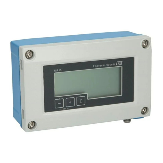
RIA15
Loop-powered 4 to 20 mA process display unit
with HART
®
communication
These Instructions are Brief Operating Instructions; they are
not a substitute for the Operating Instructions pertaining to
the device.
For detailed information, refer to the Operating Instructions
and other documentation.
Available for all device versions via:
• Internet: www.endress.com/deviceviewer
• Smart phone/Tablet: Endress+Hauser Operations App
Solutions
Services
Advertisement
Table of Contents

Related Manuals for Endress+Hauser RIA15


Summary of Contents for Endress+Hauser RIA15
- Page 1 These Instructions are Brief Operating Instructions; they are not a substitute for the Operating Instructions pertaining to the device. For detailed information, refer to the Operating Instructions and other documentation. Available for all device versions via: • Internet: www.endress.com/deviceviewer • Smart phone/Tablet: Endress+Hauser Operations App...
- Page 2 RIA15 Order code 00X00-XXXX0XX0XXX Ser. No.: X000X000000 TAG No.: XXX000 Serial number www.endress.com/deviceviewer Endress+Hauser Operations App A0023555 Endress+Hauser...
-
Page 3: Table Of Contents
RIA15 Table of contents Table of contents Document information ............4 Document conventions . -
Page 4: Document Information
Document information RIA15 Document information Document conventions 1.1.1 Safety symbols Symbol Meaning DANGER! This symbol alerts you to a dangerous situation. Failure to avoid this situation will result in DANGER serious or fatal injury. WARNING! WARNING This symbol alerts you to a dangerous situation. Failure to avoid this situation can result in serious or fatal injury. - Page 5 RIA15 Document information 1.1.3 Symbols for certain types of information Symbol Meaning Permitted Indicates procedures, processes or actions that are permitted. Preferred Indicates procedures, processes or actions that are preferred. Forbidden Indicates procedures, processes or actions that are forbidden. Indicates additional information.
-
Page 6: Registered Trademarks
Safety instructions RIA15 1.1.5 Tool symbols Symbol Meaning Flat blade screwdriver A0011220 Allen key A0011221 Open-ended wrench A0011222 Torx screwdriver A0013442 Registered trademarks HART ® Registered trademark of the HART ® Communication Foundation Safety instructions Requirements for the personnel The personnel must fulfill the following requirements for its tasks: ‣... -
Page 7: Workplace Safety
If a plastic transmitter housing is permanently exposed to certain steam and air mixtures, this can damage the housing. ‣ If you are unsure, please contact your Endress+Hauser Sales Center for clarification. ‣ If used in an approval-related area, observe the information on the nameplate. -
Page 8: Scope Of Delivery
RIA15 Ord. cd.: XXXXXXXX Front IP65 Type 4X Encl. Loop powered 4...20 mA Ser. no.: XXXXXXXXXXXXXXXXX Ext. ord. cd.: RIA15-XXXXXXX Class2 circuit or SELV circuit Ta= -40...+60°C A0019608 1 Nameplate of the process display unit (example) Order code of the device... -
Page 9: Hart ® Protocol Certification
CE mark. HART ® protocol certification The RIA15 is registered by the HART ® Communication Foundation. The device fulfills the requirements of HCF Specification, Revision 7.1. This version is downwards compatible with all sensors/actuators with HART ®... -
Page 10: Installation Instructions
Installation RIA15 Installation instructions For the dimensions of the device, see the "Technical data" section in the relevant Operating Instructions. 4.3.1 Panel housing A0017762 2 Installation instructions for the panel housing Installation in a panel with a panel cutout 92x45 mm (3.62x1.77 in), max. panel thickness 13 mm (0.51 in). - Page 11 RIA15 Installation TX20 A0017789 3 Mounting the process display unit on a pipe Mounting plate for pipe/wall mounting Weather protection cover (optional) Release the 4 housing screws Open the housing Secure the mounting plate to the rear of the device with 4 screws supplied. The optional weather protection cover can be secured between the device and the mounting plate.
-
Page 12: Wall Mounting
Installation RIA15 Wall mounting With optionally available mounting kit. A0017803 4 Mounting the process display unit on a wall Use the mounting plate as a stencil for 2 6 mm (0.24 in) bore holes, 82 mm (3.23 in) apart, and secure the plate on the wall with 2 screws (not supplied). - Page 13 RIA15 Installation Close the cover and tighten the housing screws. 4.3.3 Mounting the optional HART ® communication resistance module Panel housing ® The HART communication resistance module is available as an accessory, see section Accessories in the relevant Operating instructions.
-
Page 14: Post-Installation Check
Installation RIA15 A0020844 6 ® Mounting the optional HART communication resistance module Unplug the pluggable terminal block. Plug terminal block into the suitable plug-in position on the HART ® communication resistance module. Plug the HART ® communication resistance module into the plug-in position in the housing. -
Page 15: Wiring
RIA15 Wiring Wiring WARNING Danger! Electric voltage! ‣ The entire connection of the device must take place while the device is de-energized. Only certified devices (optionally available) may be connected in the hazardous area ‣ Observe corresponding notes and wiring diagrams in the Ex-specific supplement to these Operating Instructions. -
Page 16: Quick Wiring Guide
Wiring RIA15 Quick wiring guide Terminal Description Positive connection, current measurement Negative connection, current measurement (without backlighting) Negative connection, current measurement (with backlighting) Auxiliary terminals (electrically connected internally) Functional grounding: • Panel-mounted device: Terminal on the rear of the housing •... -
Page 17: Connection In Hart Mode
RIA15 Wiring Connection without backlighting Connection with backlighting Connection with PLC and transmitter A0019720 A0019721 1 PLC 1 PLC Connection without transmitter power supply directly in the 4 to 20 mA circuit A0017708 A0017709 2 4 to 20 mA power source... - Page 18 Wiring RIA15 The HART ® communication resistance of 230 Ω in the signal line is always necessary in the case of a low-impedance power supply. It must be installed between the power supply and the display unit. Circuit diagram / Description...
- Page 19 RIA15 Wiring Circuit diagram / Description 4-wire sensor with process display unit and loop power supply, with backlighting A0019571 HART ® resistance Current meter (optional) Sensor Power supply 4-wire device Current output with process display unit and actuator (e.g. actuator...
- Page 20 Wiring RIA15 Circuit diagram / Description Multi-drop 2-wire sensors with process display unit and loop power supply A0019575 Sensors Power supply ® HART resistance Multi-drop 2-wire sensors with process display unit and loop power supply, with backlighting A0019722 Sensors Power supply HART ®...
- Page 21 RIA15 Wiring Circuit diagram / Description 2-wire sensor with process display unit and active barrier RN221N as loop power supply RN221N A0019576 Sensor ® HART primary master ® HART resistance Optional HART ® communication resistance module A HART ® communication resistance module is available as an accessory, see section Accessories in the relevant Operating Instructions.
- Page 22 Wiring RIA15 Wiring Circuit diagram / Description 2-wire sensor with process display unit and loop power supply, without backlighting A0020839 ® HART communication resistance module Sensor Power supply 2-wire sensor with process display unit and loop power supply, with backlighting...
- Page 23 RIA15 Wiring Circuit diagram / Description 4-wire sensor with process display unit and loop power supply, without backlighting A0020837 HART ® communication resistance module Power supply of 4-wire device Sensor 4-wire sensor with process display unit and loop power supply, with...
-
Page 24: Inserting The Cable, Field Housing
Wiring RIA15 Inserting the cable, field housing TX20 A0017830 8 Inserting the cable, field housing Inserting the cable, field housing, connection without transmitter power supply (example) Release the housing screws Open the housing Open the cable gland (M16) and insert the cable. -
Page 25: Connecting To Functional Grounding
RIA15 Wiring The best results with regard to EMC are achieved in most cases with one-sided shielding on the feed side (without capacitance termination at the field device). Operation in the event of disturbance variables as per NAMUR NE21 is thus guaranteed. -
Page 26: Degree Of Protection
Wiring RIA15 TX20 A0018895 10 Functional grounding terminal in field housing TX20 A0018908 11 Ground terminal on field housing Degree of protection 5.7.1 Field housing The devices meet all the requirements of IP66. It is absolutely essential to comply with the... -
Page 27: Post-Connection Check
RIA15 Operation 5.7.2 Panel housing The front of the device meets the requirements of IP65. It is absolutely essential to comply with the following points to ensure this protection is guaranteed after mounting or servicing the device: • The seal between the front of the housing and the panel must be clean and undamaged. -
Page 28: Operating Functions
Operation RIA15 The device is operated using three operating keys on the front of the housing. The device setup can be disabled with a 4-digit user code. If the setup is disabled, a padlock symbol appears on the display when an operating parameter is selected. - Page 32 www.addresses.endress.com...