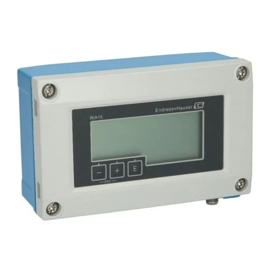
Endress+Hauser RIA15 Operating Instructions Manual
Loop-powered 4 to 20 ma process display unit with hart communication
Hide thumbs
Also See for RIA15:
- Operating instructions manual (52 pages) ,
- Brief operating instructions (32 pages) ,
- Technical information (17 pages)

Related Manuals for Endress+Hauser RIA15


Summary of Contents for Endress+Hauser RIA15
- Page 1 BA01170K/09/EN/05.15 Products Solutions Services 71300896 Valid as of FW version: 01.04.xx Operating Instructions RIA15 Loop-powered 4 to 20 mA process display unit with HART® communication...
-
Page 3: Table Of Contents
Operating matrix ..... . 34 Operating matrix in conjunction with the Micropilot FMR20 ..... 39 Endress+Hauser... -
Page 4: Document Information
Document information RIA15 Document information Document function These Operating Instructions contain all the information that is required in various phases of the life cycle of the device: from product identification, incoming acceptance and storage, to mounting, connection, operation and commissioning through to troubleshooting, maintenance and disposal. - Page 5 RIA15 Document information 1.2.3 Symbols for certain types of information Symbol Meaning Permitted Procedures, processes or actions that are permitted. Preferred Procedures, processes or actions that are preferred. Forbidden Procedures, processes or actions that are forbidden. Indicates additional information. Reference to documentation...
-
Page 6: Registered Trademarks
Document information RIA15 Registered trademarks HART® Registered trademark of the HART ® Communication Foundation Endress+Hauser... -
Page 7: Safety Instructions
‣ The operator is responsible for interference-free operation of the device. Conversions to the device Unauthorized modifications to the device are not permitted and can lead to unforeseeable dangers. ‣ If, despite this, modifications are required, consult with Endress+Hauser. Endress+Hauser... -
Page 8: Product Safety
If a plastic transmitter housing is permanently exposed to certain steam and air mixtures, this can damage the housing. ‣ If you are unsure, please contact your Endress+Hauser Sales Center for clarification. ‣ If used in an approval-related area, observe the information on the nameplate. -
Page 9: Product Description
Product description Function Process display unit RIA15 is integrated in the 4 to 20 mA/HART® loop and transmits the measuring signal in digital form. The process display unit does not require an external power supply. It is powered directly from the current loop. - Page 10 ' + ' or ' – ' . The switching time can be configured in the "EXPRT" – "SYSTM" – "TOGTM" menu. 3.2.1 RIA15 as a remote display and for operation of the Micropilot FMR20 The Micropilot is a "downward-looking" measuring system, operating based on the time-of- flight method (ToF).
- Page 11 • Digital output (HART, SmartBlue): 0 to 10 m (0 to 33 ft) or 0 to 20 m (0 to 66 ft) depending on antenna version The RIA15 can be used as a local display unit and for the basic configuration of the Micropilot FMR20 radar level sensor via HART®.
-
Page 12: Input Channels
HART® multidrop network. The RIA15 can be used as a local display unit and for the basic configuration of the Micropilot FMR20 radar level sensor via HART®. -
Page 13: Identification
The measuring system meets the legal requirements of the applicable EC guidelines. These are listed in the corresponding EC Declaration of Conformity together with the standards applied. Endress+Hauser confirms successful testing of the device by affixing to it the CE mark. -
Page 14: Hart® Protocol Certification
EAC mark. HART® protocol certification The RIA15 is registered by the HART® Communication Foundation. The device fulfills the requirements of HCF Specification, Revision 7.1. This version is downwards compatible with all sensors/actuators with HART® versions ≥ 5.0. -
Page 15: Installation
RIA15 Installation Installation Incoming acceptance, transport, storage Compliance with the permitted environmental and storage conditions is mandatory. Precise specifications for this are provided in the "Technical data" . 5.1.1 Incoming acceptance On receipt of the goods, check the following points: •... - Page 16 Installation RIA15 5.3.1 Panel housing A0017762 4 Installation instructions for the panel housing Installation in a panel with a panel cutout 92x45 mm (3.62x1.77 in), max. panel thickness 13 mm (0.51 in). 1. Slot the device into the panel cutout from the front.
- Page 17 RIA15 Installation TX20 A0017789 5 Mounting the process display unit on a pipe Mounting plate for pipe/wall mounting Weather protection cover (optional) 1. Release the 4 housing screws 2. Open the housing 3. Secure the mounting plate to the rear of the device with 4 screws supplied. The optional weather protection cover can be secured between the device and the mounting plate.
- Page 18 Installation RIA15 A0017803 6 Mounting the process display unit on a wall 1. Use the mounting plate as a stencil for 2 6 mm (0.24 in) bore holes, 82 mm (3.23 in) apart, and secure the plate on the wall with 2 screws (not supplied).
-
Page 19: Post-Installation Check
RIA15 Installation A0020785 7 Mounting the optional HART ® communication resistance module 1. Unplug the pluggable terminal block. 2. Plug terminal block into the suitable plug-in position on the HART ® communication resistance module. 3. Plug the HART ®... - Page 20 Installation RIA15 5.4.2 Display unit in the field housing • Is the seal undamaged? • Is the housing firmly screwed to the mounting plate? • Is the mounting bracket firmly secured on the wall/pipe? • Are the housing screws firmly tightened?
-
Page 21: Wiring
RIA15 Wiring Wiring WARNING Danger! Electric voltage! ‣ The entire connection of the device must take place while the device is de-energized. Only certified devices (optionally available) may be connected in the hazardous area ‣ Observe corresponding notes and wiring diagrams in the Ex-specific supplement to these Operating Instructions. -
Page 22: Connection In 4 To 20 Ma Mode
Wiring RIA15 Connection in 4 to 20 mA mode The following diagrams show how the process display unit is connected in 4 to 20 mA mode. Connection without backlighting Connection with backlighting Connection with transmitter power supply and transmitter A0017704... - Page 23 RIA15 Wiring Circuit diagram / Description 2-wire sensor with process display unit and transmitter power supply, without backlighting A0019567 Sensor Power supply ® HART resistance 2-wire sensor with process display unit and transmitter power supply, with backlighting A0019568 Sensor Power supply ®...
- Page 24 Wiring RIA15 Circuit diagram / Description Current output with process display unit and actuator (e.g. actuator valve), without backlighting A0019573 Actuator Power supply 4-wire device Current output Current output with process display unit and actuator (e.g. actuator valve), with backlighting...
- Page 25 RIA15 Wiring Circuit diagram / Description 2-wire sensor with process display unit and active barrier RN221N as transmitter power supply RN221N A0019576 Sensor HART ® primary master HART ® resistance ® Optional HART communication resistance module A HART ® communication resistance module is available as an accessory, see the "Accessories"...
- Page 26 Configuration is done using the Field Xpert SFX100 device configurator, for example. A0019580 10 Configuration of HART ® devices; example TMT162 HART ® primary master (e.g. PLC) HART ® resistance RIA15 process display unit HART ® handheld, e.g. Field Xpert SFX100 Sensor with HART ® transmitter, e.g. TMT162 Endress+Hauser...
-
Page 27: Wiring With Switchable Backlighting
RN221N. This current source is used to supply the LED backlighting of up to 7 RIA15 process display units without causing an additional voltage drop in the measurement loop. The backlighting can be switched on and off using an external switch. - Page 28 L N PE L N PE L N PE L N PE A0028249 Process display unit RIA15 3-wire connector, e.g. WAGO 221 series 2-wire sensor Terminal block on top-hat rail Active barrier, e.g. RN221N 4 to 20 mA output to the control unit Power supply Current source, e.g.
-
Page 29: Inserting The Cable, Field Housing
RIA15 Wiring Inserting the cable, field housing TX20 A0017830 11 Inserting the cable, field housing Inserting the cable, field housing, connection without transmitter power supply (example) 1. Release the housing screws 2. Open the housing 3. Open the cable gland (M16) and insert the cable 4. -
Page 30: Connecting To Functional Grounding
Wiring RIA15 therefore, cable shielding of fieldbus systems should only be grounded on one side, for example at the supply unit or at safety barriers. NOTICE If the shielding of the cable is grounded at more than one point in systems without potential matching, power supply frequency equalizing currents can occur that damage the signal cable or have a serious effect on signal transmission. -
Page 31: Degree Of Protection
RIA15 Wiring TX20 A0018908 14 Ground terminal on field housing Degree of protection 6.8.1 Field housing The devices meet all the requirements of IP67. It is absolutely essential to comply with the following points to ensure this protection is guaranteed after mounting or servicing the device: •... -
Page 32: Operation
Operation RIA15 Operation A0017719 15 Display and operating elements of the process display unit Symbol: operating menu disabled Symbol: error Symbol: warning Symbol: HART ® communication active Operating keys "-", "+", "E" 14-segment display for unit/TAG Bar graph with indicators for under range and over range 5-digit 7-segment display for measured value, digit height 17 mm (0.67 in) - Page 33 RIA15 Operation Setup Basic device settings (SETUP) Diagnostics Device information, display of error messages (DIAG) Expert Expert settings for the device setup → 37 (EXPRT) The Expert menu is protected from editing by an access code (default 0000). Endress+Hauser...
-
Page 34: Commissioning
Commissioning RIA15 Commissioning Post-installation check and switching on the device Perform the final checks before commissioning the device: • Checklist for "post-installation check" → 19. • Checklist for "post-connection check" → 31. The device starts after being connected to the 4 to 20 mA/HART® circuit. The firmware version appears on the display during the start-up phase. - Page 35 RIA15 Commissioning Setup menu (SETUP) Parameters Values visible at Description UNIT MODE = Use this function to select the unit for displaying the °C 4-20 value. If "USER" is selected, a user-defined unit can be °F entered in the TEXT parameter.
- Page 36 For Endress+Hauser transmitters/sensors with HART® communication, the diagnostic code/error code currently pending can be queried via Endress+Hauser command #231. This command is only supported by Endress+Hauser transmitters/sensors. Therefore, the TERR parameter is not visible if third-party devices are connected to the RIA15.
- Page 37 HART configuring the FMR20 level transmitter. The Level menu and all the related submenus are only visible if the RIA15 has been ordered with the "FMR20 basic configuration" option. The basic settings can be made at the Micropilot FMR20 radar level sensor via the RIA15 using this menu.
- Page 38 Commissioning RIA15 Expert menu (EXPRT); a code must be entered In addition to all the parameters in the Setup menu, the Expert menu also contains the parameters described in this table. If you call up the Expert menu, you will be asked to enter the user code (UCODE, default: 0000).
-
Page 39: Operating Matrix In Conjunction With The Micropilot Fmr20
Operating matrix in conjunction with the Micropilot FMR20 In the HART mode, it is possible to use the RIA15 with the option for the FMR20 for the basic setting of the Micropilot FMR20 radar level sensor. Further information on the FMR20, see corresponding Operating Instructions →... - Page 40 Setup -> Level (LEVEL) menu The Level menu is only visible if the RIA15 has been ordered with the "FMR20 basic setting" option and the display unit is operated in the HART mode (MODE = HART). The basic settings can be made at the Micropilot FMR20 radar level sensor via the RIA15 using this menu.
-
Page 41: Troubleshooting
RIA15 Troubleshooting Troubleshooting Error limits as per NAMUR NE 43 In Mode=4-20, the device can be configured for error limits as per NAMUR NE 43 → 37. The device displays an error message if a value is outside these limits. - Page 42 Troubleshooting RIA15 Diagnostic Short text Corrective measure Status signal Diagnostic Priority number behavior F960 HART® • Verify HART slave address Alarm communication (slave • Check electrical wiring (HART®) not responding) • Check HART® function sensor/actor C970 Multi-master collision • Check additional master in the HART® network Check (e.g.
- Page 43 0, the process display unit shows the response code briefly in the format rc xx. The meaning of the response codes is explained in the following table. For the response to the Endress+Hauser-specific HART® command #231, see the "Commissioning" section, "Diagnostics" menu → 36. Code...
-
Page 44: Spare Parts
Troubleshooting RIA15 Code Class Description Solution Error In the write-protected Check write protection in the mode FMR20 Error Span too small Check basic settings → 40 Error Access restricted Check HART® settings and firmware in the FMR20 Error Invalid span Check basic settings →... - Page 45 RIA15 Troubleshooting Date Firmware Software changes Documentation Version 11/2012 1.00.01 Original software Analog: BA01073K/09/EN/02.13 03/2013 1.01.00 HART® option, only relevant for HART® Analog: BA01073K/09/EN/03.13 version HART: BA01170K/09/EN/02.13 07/2013 1.02.00 HART® level measurement, only relevant for Analog: BA01073K/09/EN/04.13 HART® version HART: BA01170K/09/EN/03.13 11/2014 1.03.00...
-
Page 46: Maintenance
Maintenance RIA15 Maintenance No special maintenance work is required on the device. Endress+Hauser... -
Page 47: Return
The measuring device must be returned if it is need of repair or a factory calibration, or if the wrong measuring device has been delivered or ordered. Legal specifications require Endress+Hauser, as an ISO-certified company, to follow certain procedures when handling products that are in contact with the medium. -
Page 48: Disposal
Disposal RIA15 Disposal The device contains electronic components and must therefore be disposed of as electronic waste. Comply with local disposal regulations. Endress+Hauser... -
Page 49: Accessories
Various accessories, which can be ordered with the device or subsequently from Endress +Hauser, are available for the device. Detailed information on the order code in question is available from your local Endress+Hauser sales center or on the product page of the Endress+Hauser website: www.endress.com. -
Page 50: Service-Specific Accessories
The application already contains the data of your Endress+Hauser device. Endress +Hauser also takes care of maintaining and updating the data records. -
Page 51: Technical Data
RIA15 Technical data Technical data 14.1 Input Voltage drop Standard device with 4 to 20 mA communication ≤ 1.0 V ® Device with HART communication ≤ 1.9 V Display lighting additionally 2.9 V ® HART input impedance Rx = 40 kΩ... - Page 52 Technical data RIA15 14.4 Installation Mounting location Panel housing The device is designed for use in a panel. Required panel cutout 45x92 mm (1.77x3.62 in) Field housing The field housing version is designed for use in the field. The unit is mounted directly on a wall, or on a pipe with a diameter of up to 2 "...
- Page 53 RIA15 Technical data 14.6 Mechanical construction Design, dimensions Panel-mount housing 109.75 (4.32) 96 (3.78) 37 (1.46) 4.5 (0.18) mm (in) 89.5 (3.52) A0017721 21 Dimensions of the panel housing Required panel cutout 45x92 mm (1.77x3.62 in), max. panel thickness 13 mm (0.51 in).
- Page 54 The measuring system meets the legal requirements of the applicable EC guidelines. These are listed in the corresponding EC Declaration of Conformity together with the standards applied. Endress+Hauser confirms successful testing of the device by affixing to it the CE mark.
-
Page 55: Hart ® Communication
RIA15 HART ® communication HART ® communication HART ® (Highway Addressable Remote Transducer) is a well-established industry standard worldwide that has been tried and tested in the field and has an installed base of over 14 million devices. HART ®... -
Page 56: Hart ® Commands Used
RIA15 ® HART communication 15.2 HART ® commands used The process display unit uses the following HART ® universal commands: Universal command number Response data used The device identifier provides information on the device and Device unique identifier manufacturer; it cannot be changed. -
Page 57: Supported Units
RIA15 ® HART communication 15.4 Supported units The process display unit can be configured in such a way that the unit code which is sent from the slave in response to the universal command no. 3, is displayed as text, as listed in the following table (HCF-SPEC 183). - Page 58 RIA15 ® HART communication Unit code Description Display text Kelvin Millivolts Hertz Milliamperes Gallons LITER LITER Imperial gallons Igal Cubic meters Feet FEET Meters METER Barrels Inches inch Centimeters Millimeters minutes Seconds Hours HOUR Days Centistokes Centipoises Microsiemens Percent Volts...
- Page 59 RIA15 ® HART communication Unit code Description Display text Metric tons per hour Metric tons per day Pounds per second lb/S Pounds per minute lb/mi Pounds per hour lb/h Pounds per day lb/d American tons per minute TnS/m American tons per hour...
- Page 60 RIA15 ® HART communication Unit code Description Display text Normal cubic meters per hour Nm3/h Normal liters per hour Nl/h Normal cubic feet per minute F3/mi Barrel liquid (1 barrel = 31.5 U.S. gallons) UC124 Ounces ouncE Foot Pound Force...
-
Page 61: Hart ® Protocol Connection Types
RIA15 ® HART communication Unit code Description Display text Normal cubic meters Normal liters Normal cubic feet Parts per billion 170 - 219 Unit Code Expansion Tables UC170 - UC219 220 - 234 not defined UC220 - UC234 Gallons per day... -
Page 62: Device Variables For Multivariable Devices
RIA15 ® HART communication 15.6 Device variables for multivariable devices Multivariable measuring devices can transmit up to four device variables via HART ® : the Primary Variable (PV), Secondary Variable (SV), Tertiary Variable (TV) and Quaternary Variable (QV). Below you will find some examples of what default values can be set for these variables for various sensors/actors: Flowmeter, e.g. -
Page 63: Index
Supported HART® units ....57 Workplace safety ......7 Endress+Hauser... - Page 64 www.addresses.endress.com...