Table of Contents
Advertisement
PLEASE RETAIN
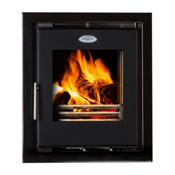
Cara Glass Non Boiler
Insert Stove
INSTALLATION AND OPERATING INSTRUCTIONS
This appliance is hot while in operation and retains its heat for a long period of time after use. Children,
aged or infirm persons should be supervised at all times and should not be allowed to touch the hot
working surfaces while in use or until the appliance has thoroughly cooled.
When using the stove in situations where children, aged and/or infirm persons are present a fireguard
must be used to prevent accidental contact with the stove. The fireguard should be
manufactured in accordance with BS 8423:2010.
Advertisement
Table of Contents

Related Manuals for Stanley Cara Glass


Summary of Contents for Stanley Cara Glass
- Page 1 PLEASE RETAIN Cara Glass Non Boiler Insert Stove INSTALLATION AND OPERATING INSTRUCTIONS This appliance is hot while in operation and retains its heat for a long period of time after use. Children, aged or infirm persons should be supervised at all times and should not be allowed to touch the hot working surfaces while in use or until the appliance has thoroughly cooled.
-
Page 2: Table Of Contents
Stanley Solid Fuel Stove Warranty ........ -
Page 3: Stanley Solid Fuel Stove Warranty
WS Service Department. All warranty claims must be reported to the Waterford Stanley Service Department and must be submitted with the prod- uct serial number (located on the bottom RH corner of the front plate), date of purchase, proof of purchase (if request- ed) and details of the specific nature of the problem. -
Page 4: Installation Checklist
INSTALLATION CHECK LIST Tick Flue System 1. Minimum Flue Height of 4.6 metres (15 feet). 2. Appliance should be connected to a 125mm (5”) flue pipe within a metre and then the flue size increased to a minimum of 150mm (6”) diameter. 3. -
Page 5: Important Operation/ Maintenance Notes
IMPORTANT OPERATION / MAINTENANCE NOTES Now that your Stanley Solid Fuel Stove is installed and no doubt you are looking forward to many comforts it will provide, we would like to give you some tips on how to get the best results from your stove. -
Page 6: Installation & Operating Instructions
Save calculation of the design heat load. these instructions for future reference. Your Cara Glass stove is supplied with the following Please note that it is a legal requirement under items: England & Wales Building Regulations that the •... -
Page 7: Flues
Fig.1 The stove must be connected to a chimney with a minimum continuous draught of 0.06 w.g. Poor draught conditions will result in poor performance. All register plates, restrictor plates, damper etc., which could obstruct the flue at a future date should be removed before connecting this appliance. -
Page 8: Fitting Instructions
Step 2 Fig.3 Ensure the floor area is level with the hearth, this area needs to be level as the insert fire is screw fixed to the floor. Remove all internal parts as per pre-assembly instructions. Step 3 Drop the flexi flue liner down through the chimney and into the fireplace. -
Page 9: Not Fully Lined Chimney
Fig.5a NOT FULLY LINED CHIMNEY (Using Closure Plate & Pipe Extension) Fig.5 Chimney Connectors Offset Adaptor Extension Pipe 15 degree Adaptor Fig.5 Fig.5b Step 3 Measure the distance to the flue outlet of the stove and compare to the chimney, decide on best orien- tation of the offset adaptor. - Page 10 Step 5 Fig 6 Mark the drill locations and drill the holes using a 1. Grate Support 2. Fixed Baffle 5.5mm drill bit. Fix the casing to the floor using the self tapping screws provided. Step 6 Lift the stove into the external casing. The stove can 3.
-
Page 11: Down Draughts
Fig 8a Fig 7a Fig 7b 5. Grate The grate simply lays into the grate support but care needs to be taken that the riddling bar will rest in the middle of the fork. 6 & 7. Side & Back Bricks Fig 8b Lay the side and back bricks in as shown in Fig.8. -
Page 12: Ventilation & Combustion Air Requirements
Fig 9 Note: Direction of wind There must not be an extractor fan fitted in the same room as the stove as this can cause the stove to emit smoke and fumes into the room. All materials used in the manufacture of air vents should be such that the vent is dimensionally stable, corrosion resistant, and no provision for closure. -
Page 13: Location
Building Regulations.’ Fig.11 LOCATION There are several conditions to be considered in selecting a location for your Stanley Glass Stove. a. Position in the area to be heated, central locations are usually best. b. Allowances for proper clearances to combustibles. -
Page 14: Floor Protection
FLOOR PROTECTION Fig.12 It is recommended that the appliance is installed on a solid, level, concrete base of non combustible hearth conforming current Building Regulations must extend 350mm in front of the unit and 250mm from the sides of the front edge. This will provide protection from sparks and embers which may fall out when stoking on refuelling. -
Page 15: Commissioning & Handover
AIR CONTROLS fuels either alone or mixed with the recommended fuels listed, nor does it cover instructions for the use The Stanley Cara Glass Insert has two independent of other fuels. air controls. The primary air control lever is the left hand lever under the fire door. -
Page 16: Technical Data
Heat Model Class to Room to Water Index Fuel Output Net Efficiency Cara Glass NB SF Stove 104.25 Wood 78.1 LIGHTING 4. Place pieces of paper and kindling on top of the Before lighting the stove check with the installer that grate and add a small quantity of fuel. -
Page 17: Refuelling
FUEL PRIMARY AIR SECONDARY AIR Anthracite Adjust for Desired Heat Output Fully Closed Coal Adjust for Desired Heat Output Fully Closed Turf/ Wood Maximum Opening of 50% Adjust for Desired Heat Output WARNING: DO NOT LEAVE BOTH AIR CONTROLS FULLY OPEN AS THIS CAN CAUSE THE STOVE TO OVERHEAT, DAMAGING THE INTERNAL COMPONENTS. -
Page 18: Monthly Maintenance
Fig.17 Fig.16 PERIODIC MAINTENANCE CHIMNEY CLEANING The chimney should be cleaned twice annually or if the stove is not used for a prolonged period during the summer period, it should be cleaned prior to commencement of usage. The chimney can be cleaned through the stove depending on the flue configuration and the flue liner should be cleaned in accordance with manufacturer's instructions. -
Page 19: Prolonged Periods Of Non Use
PROLONGED PERIODS OF NON USE (d) While awaiting the fire department watch for If the stove is to be left unused for a prolonged peri- ignition to adjacent combustibles from over- od of time then it should be given a thorough clean heated flue pipe or from embers or sparks to remove ash and unburned fuel residues. -
Page 20: Exploded View
CARA GLASS INSERT STOVE EXPLODED VIEW ASHPAN - F00997AXX 20. LH BACK BRICK - H00203AXX BAFFLE SUPPORT - F01084AXX 21. SIDE BRICK - H00207AXX BAFFLE - F01198AXX 22. RH BACK BRICK - H00208AXX 5” X 250MM STRAIGHT PIPE - F01199AXX 23. - Page 21 NOTES...
- Page 22 NOTES...
- Page 23 NOTES...
- Page 24 Manufactured by Waterford Stanley Ltd., Unit 401-403, IDA Industrial Estate, Cork Road, Waterford, Ireland. Tel: (051) 302300 Fax (051) 302315 N00547AXX Rev: 013 YS 101017...