Table of Contents
Advertisement
INSPECT THE SHIPPING CONTAINER IMMEDIATELY UPON RECEIVING YOUR UNIT. ANY DAMAGE SHOULD BE NOTED ON
FREIGHT BILL BEFORE SIGNING AND CLAIMS SHOULD BE FILLED WITH CARRIER AS SOON AS POSSIBLE. MAKE SURE THAT
13, 14 & 16 SEER SPLIT SYSTEM AIR CONDITIONERS
Conforms to UL Standard 1995. Certifi ed to
CAN/CSA Standard C22�2 No�236�
9700539
WARNING
!
ELECTRICAL SHOCK, FIRE OR
EXPLOSION HAZARD
FAILURE TO FOLLOW SAFETY WARNINGS
AND INSTRUCTIONS EXACTLY COULD RE-
SULT IN SERIOUS INJURY, DEATH OR PROP-
ERTY DAMAGE.
THIS INFORMATION IS INTENDED FOR USE
BY QUALIFIED HVAC TECHNICIANS
POSSESSING ADEQUATE BACKGROUNDS
OF ELECTRICAL AND MECHANICAL
EXPERIENCE. ANY ATTEMPT TO REPAIR
A CENTRAL AIR CONDITIONING PRODUCT
MAY RESULT IN PERSONAL INJURY AND/OR
PROPERTY DAMAGE.
THE MANUFACTURER OR SELLER CANNOT
BE RESPONSIBLE FOR THE
INTERPRETATION OF THIS INFORMATION,
NOR CAN IT ASSUME ANY LIABILITY IN
CONNECTION WITH ITS USE.
UNIT CONTAINS R-410A REFRIGERANT
AND POE COMPRESSOR OIL! USE ONLY
R-410A REFRIGERANT AND APPROVED POE
COMPRESSOR OIL.
REFRIGERANT LINES MUST BE BRAZED AND
RATED FOR R410 PRESSURES!
PROPER SERVICE EQUIPMENT IS
REQUIRED. USE ONLY R-410A APPROVED
SERVICE EQUIPMENT.
FAILURE TO USE PROPER SERVICE TOOLS
MAY RESULT IN EQUIPMENT DAMAGE OR
PERSONAL INJURY.
RATING PLATE MATCHES THE MODEL NUMBER YOU PURCHASED.
INSTALLER: P LEASE FAMILIARIZE YOURSELF WITH THIS MANUAL BEFORE
CONSUMER: RETAIN THIS MANUAL FOR FUTURE REFERENCE.
INSTALLATION AND OPERATING
!
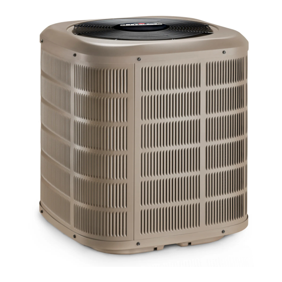
Congratulations on the purchase of your Napoleon Air Conditioner.
Napoleon's line of Split Air Conditioners offer industry leading quality
and are equipped with multiple advanced features:
FEATURES:
• 13, 14 &16 SEER effi ciencies
• Capacities from 1.5 ton to 5.0 tons
• Utilizes environmentally friendly R-410A refrigerant
• High Effi ciency Copeland Scroll Compressors
• Micro Channel Condenser
• Swept Fan Blades
MANUFACTURER RESERVES THE RIGHT TO DISCONTINUE, OR CHANGE AT ANY TIME,
SPECIFICATIONS OR DESIGNS WITHOUT NOTICE AND WITHOUT INCURRING OBLIGATIONS.
Wolf Steel Ltd�, 24 Napoleon Rd�, Barrie, ON, L4M 0G8 Canada /
Phone 866-820-8686 • Fax 705-725-1150 • www.napoleonheatingandcooling.com •
PROCEEDING WITH THE INSTALLATION. LEAVE THIS MANUAL
WITH THE APPLIANCE FOR FUTURE REFERENCE.
INSTRUCTIONS
103 Miller Drive, Crittenden, Kentucky, USA, 41030
hvac@napoleonproducts.com
IOM
Powered By:
W415-1395 / C / 06.26.2017
Advertisement
Table of Contents

Related Manuals for Napoleon 13 SEER


Summary of Contents for Napoleon 13 SEER
- Page 1 MANUFACTURER RESERVES THE RIGHT TO DISCONTINUE, OR CHANGE AT ANY TIME, SPECIFICATIONS OR DESIGNS WITHOUT NOTICE AND WITHOUT INCURRING OBLIGATIONS. REQUIRED. USE ONLY R-410A APPROVED SERVICE EQUIPMENT. Wolf Steel Ltd�, 24 Napoleon Rd�, Barrie, ON, L4M 0G8 Canada / FAILURE TO USE PROPER SERVICE TOOLS 103 Miller Drive, Crittenden, Kentucky, USA, 41030 MAY RESULT IN EQUIPMENT DAMAGE OR Phone 866-820-8686 • Fax 705-725-1150 • www.napoleonheatingandcooling.com •...
-
Page 2: Table Of Contents
024 = 2.0 Tons 030 = 2.5 Tons T=Top Discharge 036 = 3.0 Tons 042 = 3.5 Tons 13 = 13 SEER 048 = 4.0 Tons 14 = 14 SEER 060 = 5.0 Tons 16 = 16 SEER A=Air Conditioner... -
Page 3: Overview
2. OVERVIEW These instructions cover installation of Napoleon Split System Air Conditioners. Napoleon’s line of Split Air Conditioners offer industry leading quality and reliability. All outdoor units have been factory run-tested and ready for easy installation� Napoleon’s line of Split Air Conditioners are designed to perform for many years. These instructions are intended as an aid to the licensed service technician to properly install the unit. Improper installation may damage equipment, void the warranty, and can create a hazard, resulting in property damage, injury or death. Our air conditioning systems and components are designed to be installed by qualified HVAC technicians ONLY. The installation of air conditioning systems includes electrical and refrigerant connections and is regulated by a multiple sets of laws, codes and guidelines, at the federal, state and local levels. It is the installer’s responsibility to install the product in accordance with all applicable codes and regulations. It is the homeowner’s responsibility to properly maintain the equipment. NO WARRANTY is offered for the products that were installed by unlicensed/unauthorized persons. Failure to comply with this policy could lead to violations of applicable laws that are punishable. Documentation and specifications are continuously updated and subject to change. Please download the latest version of specifications and manuals at http://www.napoleonheatingandcooling.com. 3. SAFETY SAFETY SYMBOLS Understand and pay particular attention to the words DANGER, WARNING, and CAUTION and the following defi ned symbols are used throughout this manual to notify the reader of potential hazards of varying risk levels. DANGER INDICATES AN IMMINENTLY HAZARDOUS SITUATION WHICH, IF NOT AVOIDED, WILL RESULT IN DEATH OR SERIOUS INJURY. -
Page 4: Safety Rules
SAFETY RULES IMPORTANT: READ THE FOLLOWING INSTRUCTIONS COMPLETELY BEFORE INSTALLING! H6.0 WARNING THIS INFORMATION IS INTENDED FOR USE BY QUALIFIED HVAC TECHNICIANS POSSESSING ADEQUATE BACKGROUNDS OF ELECTRICAL AND MECHANICAL EXPERIENCE. ANY ATTEMPT TO REPAIR A CENTRAL AIR CONDITIONING PRODUCT MAY RESULT IN PERSONAL INJURY AND/OR PROPERTY DAMAGE. -
Page 5: Codes
1� Only trained service technicians familiar with standard service instructions and training materials should attempt installation, service, and repair of these units. Failure to follow these instructions may result in improper installation, adjustment, alteration, service, maintenance, or use that can cause explosion, fire, electrical shock, or other conditions which may cause death, personal injury, or property damage. For information or assistance, consult a qualified installer, service agency, your distributor or branch. 2� Unit contains R-410A refrigerant and POE compressor oil! Use only R-410A refrigerant and approved POE compressor oil. Refrigerant lines must be brazed and rated for R410A pressures! 3� Follow all safety codes. 4� Wear safety glasses, protective clothing, and work gloves. 5. Have fire extinguisher available. 6� Read instructions thoroughly and follow all warnings or cautions included in literature and attached to the unit. Consult federal, provincial, state, and local codes for special requirements. CODES This unit must be installed in accordance with all local codes, by-laws and regulations by those authorities having jurisdiction. Electrical connections must be made in accordance with: a. -
Page 6: Location And Clearance
5. LOCATION AND CLEARANCE wall 12” Service CLEARANCE Access Panel The minimum clearances required for installation 24” 12” and accessibility are shown below. These clearances should be followed unless otherwise approved by the manufacturer. 12” 60” Unrestricted wall wall 12” Service MIN. 24” clearance Access for service Panel Service from one side Access 24” 12” Panel 12” 12” 12”... -
Page 7: Installation
6. INSTALLATION SUPPORT Support pad: 1� The pad must be: 2” min a� separate from any structure. b. properly sized according to the size of the cabinet. No portion of the cabinet shall overhang beyond the pad. 2� The pad must be level (Fig 7). The pad location must comply with National, State, and Local codes. UNIT PLACEMENT IMPORTANT BEFORE INSTALLATION, REMOVE THE SHIPPING BRACKETS. 3� Remove screws holding four brackets to the pallet and lift off the clips (Fig 8). 4� Center, position and place the unit onto pad (Fig 9). 2” min W415-1395 / C / 06.26.2017... -
Page 8: Refrigerant Line Set Installation
REFRIGERANT LINE SET INSTALLATION 6.3.1 Refrigerant Piping Limitations • Maximum line length = 100 feet. 100’ max • Maximum vertical height = 60 feet. • Maximum vertical height = 60 feet. • Compressor crankcase heater is required for line lengths over 60 feet. • Use only the line diameters indicated in TABLE 2� W415-1395 / C / 06.26.2017... - Page 9 6.3.2 Refrigerant Line and Service Valve Connection Sizes PIPING CONNECTIONS The outdoor condensing unit must be connected to the matched indoor evaporator coil using field supplied refrigerant grade (ACR) copper tubing that is internally clean and dry. Units should be installed only with the tubing sizes for approved system combinations as specified in Table 2. NOTE • USING A LARGER THAN SPECIFIED LINE SIZE COULD RESULT IN OIL RETURN PROBLEMS. • USING TOO SMALL A LINE WILL RESULT IN LOSS OF CAPACITY AND OTHER PROBLEMS CAUSED BY INSUFFICIENT REFRIGERANT FLOW.
- Page 10 6.3.3 Line Brazing Pressure Port Cap WARNING Valve Core Service Valve Cap REFRIGERANT LINES MUST BE BRAZED AND RATED FOR R410A PRESSURES! Pressure Service Port WARNING DO NOT REMOVE SERVICE VALVE CAPS UNTIL SECTION 7. CAUTION DRY NITROGEN SHOULD ALWAYS BE SUPPLIED THROUGH THE TUBING WHILE IT IS BEING BRAZED, BECAUSE THE TEMPERATURE REQUIRED IS HIGH...
- Page 11 4. Brazing steps: a� Wrap a wet rag around the valve body to avoid heat damage and continue the dry nitrogen purge. b. Braze the refrigerant lines to the service Dry Nitrogen valves (Fig. 16 and Fig. 17)� IMPORTANT Wet Rag WHEN BRAZING LINE SET TO SERVICE VALVES POINT FLAME AWAY FROM SERVICE VALVE. Nitrogen CAUTION Braze 1 AVOID BREATHING VAPORS OR FUMES FROM BRAZING OPERATIONS. PERFORM OPERATIONS ONLY IN WELL−...
- Page 12 6.3.4 Refrigerant Line Leak Test Test for leak • Pressurize the refrigerant lines and evaporator coil to 350-400 PSIG using dry nitrogen (Fig. 19). The nitrogen pressure must be maintained for few minutes. • If pressure decay is observed, it is an indication of leak(s). • Check for leaks by using a soap solution at each brazed joint (Fig. 20). 6.3.5 Refrigerant Line Insulation • The Vapor Line must always be insulated (Fig. 21). • DO NOT allow the liquid line and vapor line to come in direct (metal to metal) contact to each other. W415-1395 / C / 06.26.2017...
-
Page 13: Evacuation
7. EVACUATION EVACUATE THE REFRIGERANT LINES AND INDOOR COIL WARNING DO NOT OPEN THE SERVICE VALVES UNTIL THE REFRIGERANT LINES AND INDOOR COIL LEAK CHECK AND EVACUATION ARE COMPLETE. REFRIGERANT CAN LEAK AND MAY CAUSING MILD TO SEVERE BURNS. • Connect the vacuum pump to evacuate the refrigerant line set and indoor coil. -
Page 14: Service Valves
8. SERVICE VALVES OPEN THE SERVICE VALVES WARNING EXTREME CAUTION MUST BE EXERCISED WHEN OPENING THE LIQUID LINE SERVICE VALVE. TURN COUNTERCLOCKWISE UNTIL THE VALVE STEM JUST TOUCHES THE ROLLED EDGE. NO TORQUE IS REQUIRED. FAILURE TO FOLLOW THIS WARNING WILL RESULT IN ABRUPT RELEASE OF SYSTEM CHARGE AND MAY RESULT IN PERSONAL INJURY AND/OR PROPERTY DAMAGE. -
Page 15: Electrical
9. ELECTRICAL WARNING ONLY COPPER CONDUCTORS MUST BE USED FOR ALL FIELD WIRING AND BE IN ACCORDANCE WITH LOCAL, NATIONAL, FIRE, SAFETY AND ELECTRICAL CODES. THIS UNIT MUST BE GROUNDED WITH A SEPARATE GROUND WIRE IN ACCORDANCE WITH THE CODES MENTIONED ABOVE. Make sure that electrical supply meets the values specified on the unit nameplate and wiring label. Power wiring, disconnect switches, control (low voltage) wiring and over current protection must be supplied by the installer. Wire size must be sized per National and Local Electrical codes requirements. - Page 16 9.1.2 High Voltage Disconnect Switch • Install a separate disconnect switch at the outdoor unit (Fig. 26). 9.1.3 High Voltage Ground Ground the outdoor unit per national, state, provincial and local code requirements (Fig. 27). Components: 1� Contactor 2� Dual Run Capacitor 3� Ground Lug 4� Thermostat Control Wire Feed 5. High Voltage Power Cable Feed 6� Compressor and High Pressure Switch Wire Feed 9.1.4 Thermostat • Room thermostat (purchased separately) should be installed approximately in the center of the conditioned area on an INSIDE wall and 5 feet (1.5m) above the floor.
-
Page 17: Wiring Diagram
9.1.5 Wiring Diagram W415-1395 / C / 06.26.2017... -
Page 18: Start Up
10. START UP Perform the following steps: 1� Set System Thermostat to OFF (Fig. 29). day: 2� Turn disconnect switch ON (Fig. 30) to apply thu: HOLD time: power to the indoor and outdoor units. 18:30 SYSTEM PROG/MAN AUTO COOL HEAT Wait: 3� If no crankcase heater accessory is used, wait five (5) minutes and go to Step 5. 4� Wait one (1) hour before starting the unit, if compressor crankcase heater accessory is used and the Outdoor Ambient is below 70ºF. Refer to (Fig. 31). day: thu: HOLD time: 5. Set system thermostat to ON (Fig. 32). 18:30 SYSTEM PROG/MAN AUTO COOL HEAT... -
Page 19: System Charge Adjustment
11. SYSTEM CHARGE ADJUSTMENT WARNING REFRIGERANT CHARGING MUST ONLY BE ATTEMPTED BY QUALIFIED CONTRACTORS. IMPROP- ER SYSTEM CHARGE CAN REDUCE SYSTEM CAPACITY AND MAY CAUSE EQUIPMENT DAMAGE. 11.1 SYSTEM TOTAL CHARGE WARNING DO NOT LEAVE THE SYSTEM OPEN TO THE ATMOSPHERE. DO NOT ATTEMPT TO PUMP “TOTAL SYSTEM CHARGE”... -
Page 20: Adjusting System Charge For Systems Using Fixed Orifice
Check the nameplate for unit specific designed subcooling: i� If subcooling is low and superheat is normal, add charge to raise the subcooling to 7°F to 9°F. ii� If subcooling is low and superheat is high, add charge to raise the subcooling to 7°F to 9°F, and adjust TXV if required. iii� If subcooling and superheat is low, adjust the TXV to 7°F to 9°F superheat and add or remove charge if required. iv� If subcooiing is normal and superheat is low, adjust the TXV to raise the superheat to 7°F to 9°F and remove charge if required. v� If subcooling is normal and superheat is high, adjust the TXV to lower the superheat to 7°F to 9°F and add charge if required. vi� If subcooling is high and superheat is normal, remove charge to lower the subcooling to 7°F to 9°F. vii� If subcooling is high and superheat is low, remove charge to lower the subcooling to 7°F to 9°F and adjust TXV. viii� If subcooling and superheat is high, adjust the TXV to lower the superheat to 7°F to 9°F and remove or add charge if required. 11.3 ADJUSTING SYSTEM CHARGE FOR SYSTEMS USING FIXED ORIFICE Procedure: 1� Follow the steps 1-4 from paragraph 10.2. 2� Check superheat. The system superheat should be adjusted according to TABLE 3. A dash indicates that charging at this condition should not be attempted. Slugging may occur, leading to compressor damage. R-410A Charging Chart Outdoor Evaporator Suction Pressure - PSIG Ambient... -
Page 21: Checkout Procedures
12. CHECKOUT PROCEDURES Final phases of this installation are the unit Operational and Checkout Procedures. To obtain proper performance, all units must be operated and charge adjustments made. 12.1 INSTRUCTING THE OWNER • Assist owner with processing warranty cards and/or online registration. • Review Owners Guide and provide a copy to the owner and guidance on proper operation and maintenance. Instruct the owner or the operator how to start, stop and adjust temperature setting. • Instruct the owner on proper operation and maintenance of all other system components. IMPORTANT PERFORM A FINAL UNIT INSPECTION TO BE SURE THAT FACTORY TUBING HAS NOT SHIFTED DURING SHIPMENT. ADJUST TUBING IF NECESSARY SO TUBES DO NOT RUB AGAINST EACH OTHER WHEN THE UNIT RUNS. -
Page 22: Air Conditioning Troubleshooting
13. AIR CONDITIONING TROUBLESHOOTING TABLE 4. POSSIBLE CAUSE CORRECTION Unit will not operate Power disconnected or loose connection Check voltage at contactor. Blown fuse / breaker tripped Replace fuses / reset breaker Thermostat out of calibration is set too high Reset Contactor defective Check for 24VAC at contactor coil, replace if open... - Page 23 Normal suction Refrigerant overcharge Correct system charge pressure Outdoor fan not running Repair or replace Air or non-condensables in system Recover refrigerant, evacuate and recharge TABLE 4. CONT. Low head pressure; Expansion device stuck in open position Replace expansion device High suction Defective compressor valves Replace compressor...
-
Page 24: Maintenance
14. MAINTENANCE 14.1 INDOOR 1� Check air filters and replace if necessary. 2� The evaporator coil should be inspected annually for blockages. 3� Vacuum or spray the coil fins with clean water to remove dust and dirt. 4� Refer to the furnace or air handler instructions for filter and blower motor maintenance 5. The indoor coil and drain pan should be inspected and cleaned regularly to prevent odors and bacterial growth and to assure proper drainage. 14.2 OUTDOOR • Check the condenser annually for blockages and remove foreign objects blocking the condenser. CAUTION DO NOT USE COIL CLEANERS TO CLEAN OUTDOOR CONDENSING COIL. CLEANERS CONTAINING HYDROGEN FLUORIDE, HYDROXIDES, CHLORIDES, AND SULFATES CAN GREATLY REDUCE THE LIFETIME OF THE ALUMINUM CONDENSING COIL. •... -
Page 25: Owner's Service Information
15. OWNER’S SERVICE INFORMATION TABLE 5. HOMEOWNER’S REFERENCE TABLE Model No� Serial No� (serial number located on bottom of inside door) Date Installed Contractor Contact Address Postal Code/Zip Code Telephone No. After Hours No. If different from Installation Contractor: Service Tech. Telephone No. After Hours No. NOTE: H28.1 W415-1395 / C / 06.26.2017... -
Page 26: Warranty
• by email: hvac@napoleonproducts.com • or mail to , 24 Napoleon Road, Barrie, Ontario L4M 0G8 Canada w w w . n a p o l e o n h e a t i n g a n d c o o l i n g . c o m H2.7... - Page 27 43.1 W415-1395 / C / 06.26.2017...
- Page 28 NAPOLEON CELEBRATING OVER 40 YEARS OF HOME COMFORT PRODUCTS 7200, Route Transcanadienne, Montréal, Québec H4T 1A3 24 Napoleon Road, Barrie, Ontario, Canada L4M 0G8 214 Bayview Drive, Barrie, Ontario, Canada L4N 4Y8 103 Miller Drive, Crittenden, Kentucky, USA 41030 Phone: 1-866-820-8686 napoleonproducts.com...