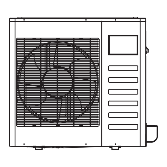
Summary of Contents for Napoleon Split Universal Type
- Page 1 INSTALLATION MANUAL Split Universal Type Thank you very much for purchasing our air conditioner, Before using your air conditioner , please read this manual carefully and keep it for future reference.
-
Page 2: Table Of Contents
CONTENTS PAGE Install according to this installation instructions strictly. If installation is defective, it will cause water leakage, electrical shock and fire. 1. PRECAUTIONS..............Use the attached accessories parts and specified parts 2. INSTALLATION INFORMATION ..........for installation. otherwise, it will cause the set to fall, water leakage, 3. -
Page 3: Installation Information
2. INSTALLATION INFORMATION If the refrigerant leaks during installation, ventilate the area immediately. Toxic gas may be produced if the refrigerant comes into the place contacting with fire. To install properly, please read this "installation manual" at The temperature of refrigerant circuit will be high, please first. -
Page 4: Outdoor Unit Installation
3. OUTDOOR UNIT INSTALLATION NOTE 3.1 Installation Place All the pictures in this manual are for explanation purpose only. They may be slightly different from the The outdoor unit should be installed in the location that air conditioner you purchased(depend on model).The meets the following requiements: actual shape shall prevail. - Page 5 3.2 Space of installation and maintenance 1. Split type outdoor unit (Wall or obstacle) ≥100 Air inlet >300mm Maintain channel Air inlet >600mm Air outlet Fig.3-5 3.3 Moving and installation Fig.3-7 Since the gravity center of the unit is not at its physical center, so please be careful when lifting it with a sling.
-
Page 6: Install The Connecting Pipe
4. INSTALL THE CONNECTING PIPE The Procedure of Connecting Pipes Drill a hole in the wall (suitable just for the size of the wall Check whether the height drop between the indoor unit conduit), then set on the fittings such as the wall conduit and and outdoor unit, the length of refrigerant pipe, and the its cover. - Page 7 Connect the indoor unit at first, then the outdoor Closing stop valve unit. Remove the cap and turn the valve clockwise with the hexagon wrench. Securely tighten the valve until the shaft contacts the Bend the tubing in proper way. Do not harm to them. main bodyseal.
-
Page 8: Connective Diagram
Indoor Outdoor unit CAUTION unit Ga s s ide Refrigerant cannot be charged until field wiring has been Liq uid si de completed. Stop valv e Refrigerant may only be charged after performing the leak Fig.4-6 test and the vacuum pumping. When charging a system, care shall be taken that its Manifo ld valv e maximum permissible charge is never exceeded, in view of... -
Page 9: The Specification Of Power
The Specification of Power NOTE (Refer to Table6-1) Remark per EMC Directive 2004/108/EC 6. Outdoor unit For to prevent flicker impressions during the start of the compressor (technical process) following installation Remove the electric parts cover from the outdoor unit. conditions do apply. - Page 10 Table 6-1 MODEL 1 P h a s e 1 P h a s e 1 P h a s e 1 P h a s e PHASE POWER (outdoor) VOLT 208/230 V 208/2 30V 208/2 30V 208/2 30V CIRCUIT BREAKER/FUSE(A) installation manual...
- Page 11 QSWI-002AEN The design and specifications are subject to change without prior notice for product improvement.Consult with the sales agency or manufacturer for details. installation manual...
- Page 12 installation manual...
- Page 13 installation manual...
- Page 14 installation manual...
- Page 15 installation manual...
- Page 16 installation manual...
- Page 17 installation manual...
- Page 18 installation manual...
- Page 19 installation manual...
- Page 20 installation manual...
- Page 21 installation manual...
- Page 22 installation manual...
- Page 23 installation manual...
- Page 24 installation manual...


