Raymarine ST60 Tridata Owner's Handbook Manual
Raymarine st60 tridata instrument owner's handbook
Hide thumbs
Also See for ST60 Tridata:
- Owner's handbook manual (64 pages) ,
- Operating manual (38 pages) ,
- Commissioning manual (24 pages)

Related Manuals for Raymarine ST60 Tridata


Summary of Contents for Raymarine ST60 Tridata
- Page 1 ST60 Tridata Instrument Owner’s Handbook Document number: 81040-4 Date:10 November 2002...
- Page 2 Raymarine, ST60 and SeaTalk are trademarks of Raymarine Limited © Handbook contents copyright Raymarine Limited 2002...
-
Page 3: Emc Conformance
Safety notices WARNING: Product installation & operation This equipment must be installed and operated in accordance with the Raymarine instructions provided. Failure to do so could result in personal injury, damage to your boat and/or poor product performance. WARNING: Electrical safety Make sure you have switched off the power supply before you start installing this product. - Page 4 ST60 Tridata Instrument Owner’s Manual...
-
Page 5: Table Of Contents
Contents Important information ...i Safety notices ... i EMC conformance ... i Handbook information ... i Introduction ... vii Data inputs ...vii SeaTalk ...vii Stand alone operation ...viii Remote control ...viii Mounting options ...viii Parts supplied ... ix Chapter 1: Operation ...1 1.1 Getting started ... - Page 6 Depth offset ... 29 Shallow alarm lock ... 30 Speed ... 31 Set speed units ... 31 Set speed resolution ... 31 Set log units ... 31 Setting the correct speed ... 31 Adjust to SOG ... 33 ST60 Tridata Instrument Owner’s Manual...
- Page 7 Set temperature units ... 33 Temperature calibration ... 33 Timer alarm buzzer ... 33 Leaving User calibration ... 33 4.3 Intermediate calibration ... 34 Speed calibration ... 35 Leaving Intermediate calibration ... 39 4.4 Dealer calibration ... 39 User calibration on/off ... 39 Response settings ...
- Page 8 ST60 Tridata Instrument Owner’s Manual...
-
Page 9: Introduction
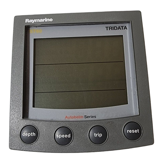
Introduction Thank you for purchasing a Raymarine product. We are sure your ST60 instrument will give you many years of trouble-free operation. This handbook describes how to install and use the Raymarine ST60 Tridata instrument. This instrument provides accurate depth, speed, trip and timer information, on a high quality Liquid Crystal Display (LCD). -
Page 10: Stand Alone Operation
SeaTalk network. Stand alone operation In Stand alone operation, the ST60 Tridata instrument is connected only to the relevant transducer and does not display information from, or provide information to, any other instruments. -
Page 11: Parts Supplied
Spare spade terminals are also provided, to re-terminate the transducer cable if it has to be cut to facilitate installation. Note: The above packing list is for an ST60 Tridata system. Where an instrument is purchased separately, Speed and Depth transducers are... - Page 12 ST60 Tridata Instrument Owner's Handbook ST60 Tridata Instrument Owner’s Manual TRIDATA depth speed trip Current Boat speed depth Trip Maximum Shallow Alarm speed Threshold reset 3s to Reset Water temperature reset 3s to Reset Deep Average speed alarm threshold Count-up timer...
-
Page 13: Chapter 1: Operation
Trip, log, water temperature & timer Screen layout 1.2 Normal operation Use the flow charts in this Chapter to operate your ST60 Tridata instrument. Flow charts are provided for: • Using the On master instruments, this also gives access to depth alarm threshold information, and allows you to set the alarm thresholds. -
Page 14: Depth
It also shows a depth trend indicator, which is either an up arrow to show seabed rising or a down arrow to show seabed falling. ST60 Tridata Instrument Owner’s Manual trip key to gain access to log, trip, water temperature and... -
Page 15: Depth Alarm Threshold Displays
Chapter 1: Operation If for any reason depth information is lost, the DEPTH title will flash once per second and the displayed depth value will be the last good reading. Depth alarm threshold displays The alarm threshold displays are available if the instrument is operating as a master. -
Page 16: Maximum Speed
Velocity made good (to windward) Velocity made good (VMG) information is available if your instrument is part of a SeaTalk system to which a SeaTalk-compatible wind instrument is also connected. ST60 Tridata Instrument Owner’s Manual Boat speed speed speed Average speed reset key for 2 seconds. -
Page 17: Trip
Chapter 1: Operation Trip key gives access to log, trip, water temperature and timer trip displays, as shown in the Using the trip key illustration. Water temperature trip Count-up timer trip Race start timer 1 To enter/leave adjust mode, press trip reset momentarily... -
Page 18: Trip Screen
3. Use either the trip or reset key to set the required value. 4. Simultaneously press the trip and reset keys to save the value and leave the race-start timer adjust mode. ST60 Tridata Instrument Owner’s Manual reset key for 3 seconds. -
Page 19: Alarms
Chapter 1: Operation If you are using one of the race-start timers and the timer buzzer is enabled, the buzzer will: • Double-beep every minute. • Beep three times at the start of the last 30 seconds. • Beep once for each of the last 10 seconds. •... -
Page 20: Contrast
1.5 Remote control When it is connected to SeaTalk, the ST60 Tridata instrument can be controlled remotely with a SeaTalk Remote Keypad Unit. Remote control of an instrument is indicated by a REMOTE legend on the display, to indicate that the keypad has control. -
Page 21: Chapter 2: Maintenance And Faultfinding
2.1 Maintenance Servicing and safety • Raymarine equipment should be serviced only by authorised Rayma- rine service technicians. They will ensure that servicing procedures and replacement parts used will not affect performance. There are no user-serviceable parts in any Raymarine product. -
Page 22: Cabling
(see Chapter 3, Installation) are still being met before further investigating the problem. Fixing faults All Raymarine products are subjected to comprehensive test and quality assurance programmes prior to packing and shipping. However, if a fault occurs, the following table may help to identify and rectify the problem. -
Page 23: Technical Support
As well as providing a comprehensive Frequently Asked Questions section and servicing information, it also gives e-mail access to the Raymarine Technical Support Department and a details of the locations of Raymarine agents, worldwide. Telephone help line If you do not have access to the world wide web, please call:... -
Page 24: Help Us To Help You
When requesting service, please quote the following product information: • Equipment type. • Model number. • Serial number. • Software issue number. The Software issue number can be ascertained by means of the Intermediate Calibration facility, see Chapter 4, Calibration. ST60 Tridata Instrument Owner’s Manual... -
Page 25: Chapter 3: Installation
Chapter 3: Installation Chapter 3: Installation This chapter describes how to install the ST60 Tridata instrument, and associated Speed and Depth transducers. The transducers are fitted in the hull of the vessel and connected to the rear of the instrument. The actual type of transducers depends on the type of hull in which they are to be installed. - Page 26 Wood Other transducer types are also available for specific requirements. For further details, contact your local Raymarine dealer. For accurate speed and depth readings the transducers should be sited within the clear water flow areas indicated by the shaded areas in the following diagram.
-
Page 27: Instrument
Chapter 3: Installation • Be as near as possible to the centre line of the vessel. • Be clear of other through-hull fittings or projections. • Have sufficient clearance inside the hull to fit the nut. • Have 100 mm (4 in) of headroom to allow for withdrawal. In addition to the above requirements, the depth transducer must be mounted within 10 Maximum transducer angle... -
Page 28: Emc Installation Guidelines
ST60 instrument dimensions EMC Installation Guidelines All Raymarine equipment and accessories are designed to the best industry standards for use in the recreational marine environment. Their design and manufacture conforms to the appropriate Electromagnetic Compatibility (EMC) standards, but correct installation is required to ensure that performance is not compromised. -
Page 29: Suppression Ferrites
Raymarine equipment. Always use the ferrites supplied by Raymarine. Connections to Other Equipment If your Raymarine equipment is to be connected to other equipment using a cable not supplied by Raymarine, a suppression ferrite MUST always be attached to the cable near the Raymarine unit. -
Page 30: Procedures
If you have ordered the flush mounting option a low-profile bezel and four fixing screws are also provided. Fitting the instrument The ST60 Tridata instrument can be installed using one of a number of different mounting options: •... -
Page 31: Flush Mounting
Chapter 3: Installation Surface mounting 2. Apply the surface mount template (supplied at the rear of this hand- book) to the selected location and mark the centres for the fixing studs (1) and the aperture (3) that will take the rear casing of the instrument. 3. - Page 32 5. Using the four, self-tapping screws (9) provided, secure the instru- ment and bezel together. Fit the screws from the rear of the instrument and tighten them sufficiently to secure the instrument and bezel together. DO NOT OVERTIGHTEN. ST60 Tridata Instrument Owner’s Manual D4537-2...
- Page 33 Chapter 3: Installation Fitting the low profile bezel Flush mounting procedure Flush mount your instrument (see the Flush mounting illustration) as follows: 1. Assemble the ST60 instrument and low-profile bezel as described under Fitting the low-profile bezel. 2. Ensure that: •...
-
Page 34: Bracket Mounting
To bracket mount your ST60 instrument, do so in accordance with the Control Unit Mounting Bracket Instruction Sheet. ST60 Tridata Instrument Owner’s Manual D5462-1... -
Page 35: Fitting Transducer
Running transducer cable Each transducer type has a 14 m (45 ft) cable fitted with spade terminals for connection to the ST60 Tridata instrument. The manner in which you run the cable will depend on the locations of the transducers and instrument. -
Page 36: Connecting The Instrument
Where a SeaTalk system includes an autopilot, the power for the system is provided by the autopilot. A range of Raymarine SeaTalk extension cables is available to connect separated instruments. These cables are supplied with a SeaTalk connector fitted to each end. A junction box can be used to join cables. -
Page 37: Power Supply Connections
Chapter 3: Installation Cable from Depth transducer Cable from Speed transducer Connections to ST60 Tridata instrument Power supply connections SeaTalk systems CAUTION: When instruments are connected to SeaTalk, ensure that the power supply for the SeaTalk 12 V line is protected by a 5 A fuse. - Page 38 Cut back and insulate the yellow wire. 4. Connect the screen to the power supply 0 V terminal. 5. Connect the red wire via a 3 A over-current circuit breaker to the power supply +12 V terminal. ST60 Tridata Instrument Owner’s Manual Screen Screen Instruments...
-
Page 39: Chapter 4: Calibration
Calibration Chapter 4: Calibration 4.1 Introduction The ST60 Tridata instrument is set up with factory-programmed default settings, so in order to optimise the performance of the instrument on board a particular vessel, the procedures in this Chapter must be carried out immediately after the completion of installation and before the equipment is used for navigational purposes. - Page 40 Set timer alarm buzzer on or off. Separate routines are provided for the User calibration of the depth and speed functions. To carry out either of these routines: 1. Power up the ST60 Tridata instrument. To start User calibration depth...
-
Page 41: Depth
Calibration Depth To calibrate the depth functions: 1. With the User calibration entry screen displayed, press the 2. Referring to the User calibration - depth illustration, carry out the cal- ibration procedure. Use the and the Depth units You can set either FEET or METRES. Set depth offset User calibration - depth... -
Page 42: Shallow Alarm Lock
Depth offsets Shallow alarm lock When set to on, prevents alteration to the shallow depth alarm threshold. ST60 Tridata Instrument Owner’s Manual (decrement) and (increment) keys to set the required reset +ve offset... -
Page 43: Speed
Calibration Speed To calibrate the speed functions: 1. With the User calibration entry screen displayed, press the speed key. 2. Referring to the User calibration - speed illustration, carry out the calibration procedure. Use the speed key to cycle from screen to screen and the trip and reset keys to set the required values at each screen (except Adjust to SOG display). - Page 44 Set speed units speed Set speed resolution speed Set log units speed User calibration - speed ST60 Tridata Instrument Owner’s Manual Set timer alarm speed Setting the correct speed Adjust to SOG If SOG available from SeaTalk &...
-
Page 45: Adjust To Sog
Calibration Adjust to SOG The Adjust to SOG screen is displayed only if SOG data is available from SeaTalk. The current SOG is displayed in the bottom section of the display (SG12.8 in the illustration), and the current speed registered by the instrument, as large figures in the middle section of the display (12.3 in the illustration). -
Page 46: Intermediate Calibration
Note: You must not allocate more than one master depth instrument in any system. 3. Press the trip and reset keys simultaneously again, to leave the adjust mode. ST60 Tridata Instrument Owner’s Manual depth key to select the Instrument status screen. trip... -
Page 47: Speed Calibration
The speed calibration procedure involves carrying out two runs over a measured distance, to enable a calibration factor to be determined and applied to your ST60 Tridata instrument, to ensure optimum accuracy. Each calibration run comprises outward and return legs, to minimise the affect of tidal drift when the calibration factor is determined. - Page 48 The displayed distance freezes. This value should be very close to the actual (measured) distance of the calibration run. 8. Press the factor. ST60 Tridata Instrument Owner’s Manual key to proceed to the Calibration run length speed key to increment the run length value. You...
- Page 49 Calibration from Intermediate calibration (Instrument status display) Calibration run length Carry out the return leg of the first cal run At the end Press speed of the return cal run To store the calibration factor, press Speed calibration - sheet 1 trip reset trip...
- Page 50 Note: At the end of this second run, the text End alternating with the new calibration factor is displayed at the bottom of the screen. 10. Press the speed key to leave distance calibration and return to the Instrument status screen. ST60 Tridata Instrument Owner’s Manual press speed At the start of...
-
Page 51: Leaving Intermediate Calibration
Calibration Leaving Intermediate calibration Hold down the exit Intermediate calibration and resume normal operation. 4.4 Dealer calibration The Dealer calibration procedures enable the following parameters to be set: • User calibration on/off. • Speed response. • Depth response. • Boat show mode on/off. Dealer calibration also gives access to the Factory defaults screen. - Page 52 Speed response depth Depth response Dealer calibration ST60 Tridata Instrument Owner’s Manual Hold down depth speed for approximately 12 seconds trip reset Calibration on/off At each screen use either trip reset to set the required values depth depth Factory...
-
Page 53: Boat Show Mode
Calibration Boat show mode CAUTION: Do NOT enable this mode. It must only be used for demonstration purposes. Ensure that the Boatshow Mode Use is set to OFF. If necessary, use the trip reset Factory defaults You can use this screen to reset the operating parameters to the factory default values. - Page 54 ST60 Tridata Instrument Owner’s Manual...
- Page 55 Drill 5mm (3/16in) diameter ST60 Surface Mount Template Machine hole 90mm (3.54in) diameter Shaded areas to be removed Drill 5mm (3/16in) diameter D4436-1...
- Page 57 ST60 Flush Mount Template 4 holes 6 mm diameter Shaded area to be removed 109 mm D4437-1...