
Related Manuals for Clarke CA30 20B


Summary of Contents for Clarke CA30 20B
- Page 1 Clarke CA30 20B and 17E Service Manual Model numbers: CA30 20B - CLARKE510B CA30 17E - CLARKE430C English 12/15 Revised 2/16 Form No. 56043171...
-
Page 2: Table Of Contents
Service Manual – Clarke CA30 20B and 17E Contents General Information General Machine Description Service Manual Purpose and Application Other Reference Manuals and Information Sources Parts And Service Name Plate Safety Symbols General Safety Instructions Property Damage Messages 120 VAC Power Cord Requirements (Corded Machine) - Page 3 Service Manual – Clarke CA30 20B and 17E Whole Machine Not Functioning Machine Enable Circuit Power, Vacuum, Solution, and Brush Switches Removal and Installation Rear Covers (Control Cover) Control Panel Control Board Brush Motor relay Batteries Setting AGM/Wet Battery Type...
- Page 4 Service Manual – Clarke CA30 20B and 17E Squeegee System Functional Description Troubleshooting Floor Streaks Maintenance and Adjustment Squeegee Blade Changing Squeegee Trim Adjustment...
-
Page 5: General Information
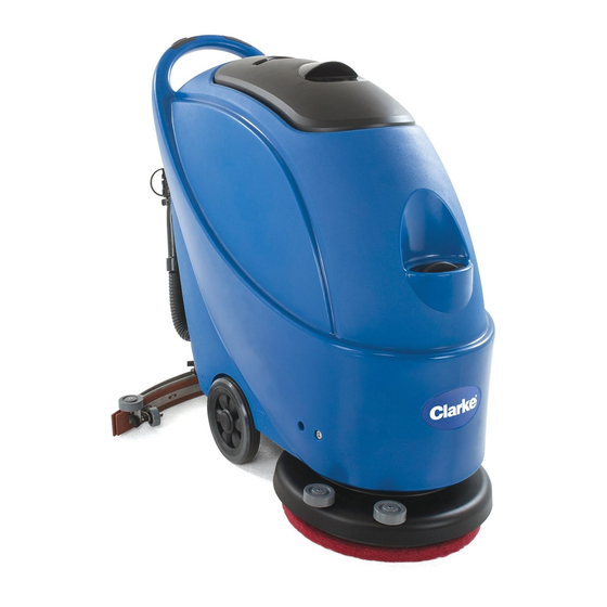
Service Manual – Clarke CA30 20B and 17E General Information General Information General Machine Description The CA30 is a walk-behind commercial floor scrubbing machine designed to wash and dry commercial floors. The machine is powered by either on-board batteries (Battery version) or with electric mains via power cord (corded version). -
Page 6: Safety
Service Manual – Clarke CA30 20B and 17E General Information Safety Symbols It is important for you to read and understand this manual. The information it contains relates to protecting your safety and preventing problems. The symbols below are used to help you recognize this information. -
Page 7: Property Damage Messages
Service Manual – Clarke CA30 20B and 17E General Information Property Damage Messages − Storage and operation temperature must be above 0°C and a humidity between 30% and 95%, non-condensing. − Before use, all doors and hoods should be properly latched. -
Page 8: Lifting The Machine
Service Manual – Clarke CA30 20B and 17E General Information Lifting The Machine Caution! Never work under a machine without safety stands or blocks to support the machine. Transporting The Machine Caution! Before transporting the machine on an open truck or trailer, make sure that . . . -
Page 9: Maintenance Schedule
Service Manual – Clarke CA30 20B and 17E General Information Maintenance Schedule Daily, Weekly/ Every 6 Procedure after use Monthly Months Annually Charge Battery Clean squeegee blades Inspect pad/brush Clean solution and recovery tanks Inspect power cord (corded model) Inspect squeegee blades for damage... -
Page 10: Know Your Machine
Service Manual – Clarke CA30 20B and 17E General Information Know Your Machine CA30 20B Brush Switches 10. Squeegee Lift Handle 19 Solution Tank Fill 28 Vacuum Tube Handle 11. Recovery Tank Drain 20 Scrub Deck 29 On-Board Charger Control Panel 12. -
Page 11: Ca30 17E
Service Manual – Clarke CA30 20B and 17E General Information CA30 17E Brush Switches 10. Squeegee Lift Handle 19 Solution Tank Fill 28 Vacuum Tube Handle 11. Recovery Tank Drain 20 Scrub Deck 29 Electrical Box Control Panel 12. Squeegee Pivot... -
Page 12: Control System (Corded Model)
Service Manual – Clarke CA30 20B and 17E Control System (Corded Model) Control System (Corded Model) Functional Description The CA30 17E utilizes switch and relay logic for machine control. It receives operator inputs through switches, and activates various solenoids and relays to control components. Most of the components operate at line voltage, except for the scrub switches and scrub control relay, which operate at 24 volts, DC. -
Page 13: Schematic
Service Manual – Clarke CA30 20B and 17E Control System (Corded Model) Schematic The following shows the electrical controls schematic. Each of the functions are further described in the subsequent sections. CONTROL PANEL Brush Switches 24V DC Power Supply POWER... -
Page 14: Solution Solenoid
Service Manual – Clarke CA30 20B and 17E Control System (Corded Model) Solution Solenoid The solution solenoid is a 120-volt magnetically controlled valve that permits fluid to gravity-flow to the scrub deck. Power to the solenoid first passes through the main power switch, then the solution switch. -
Page 15: Scrub Control Relay
Service Manual – Clarke CA30 20B and 17E Control System (Corded Model) Scrub Control Relay The scrub control relay permits low-voltage control from the operator’s scrub switches to control both the solution solenoid and the brush motor, while still permitting the operator to control whether the solution system is active or not active when the brush is active. -
Page 16: Troubleshooting
Service Manual – Clarke CA30 20B and 17E Control System (Corded Model) Troubleshooting Warning! Risk of electrical shock. Some of the procedures below require examining parts of the machine while electrical power is present. Use care when examining or troubleshooting the machine when power is present. -
Page 17: Removal And Installation
Service Manual – Clarke CA30 20B and 17E Control System (Corded Model) Removal and Installation Rear Covers (Control Cover) The rear covers provide access to the motor capacitors and the system relays. Even though the upper and lower covers are separable, it is best to treat them as a single cover during removal and replacement. -
Page 18: Control Panel
Service Manual – Clarke CA30 20B and 17E Control System (Corded Model) Control Panel The control panel contains the machine control switches and the DC power supply for the scrub relay. The machine’s relays are located below the control panel. -
Page 19: Relays And Brush Motor Capacitors
Service Manual – Clarke CA30 20B and 17E Control System (Corded Model) Relays and Brush Motor Capacitors The relays and brush motor capacitors are located below the control panel, but to access them, they must be removed from below. 1. Remove the... -
Page 20: Control System (Battery Model)
Control System (Battery Model) Functional Description The CA30 20B utilizes a main machine controller to turn on various machine functions. It receives operator switch inputs, and activates various solenoids and components. Each of the machine components is described below. Refer to the machine... -
Page 21: Battery Charger
Service Manual – Clarke CA30 20B and 17E Control System (Battery Model) Battery Charger The battery charger is semi-autonomous, and is always connected to the batteries unless the main battery disconnect is unplugged. The charger is microprocessor-controlled to provide the optimal charge-curve to the batteries depending on the battery type. -
Page 22: Schematic
Service Manual – Clarke CA30 20B and 17E Control System (Battery Model) Schematic The following shows the electrical controls schematic. Battery Meter CONTROL PANEL SOLUTION POWER VACUUM SWITCH SWITCH SWITCH Brush Switches Hour Meter +Common Scrub Active Solution S4 Vacuum S3... -
Page 23: Troubleshooting
Service Manual – Clarke CA30 20B and 17E Control System (Battery Model) Troubleshooting The following sections present some common troubleshooting scenarios based on symptoms. Whole Machine Not Functioning The symptom of “whole machine not functioning” means that the vacuum motor does not run, brush motor does not run, and solution solenoid does not engage. - Page 24 Service Manual – Clarke CA30 20B and 17E Control System (Battery Model) Voltage between Machine Enable and +Com Charger relay Charger and Power resistance w/o Open circuit at Open circuit at Short Circuit † Switch Status Normal control board ‡...
-
Page 25: Power, Vacuum, Solution, And Brush Switches
Service Manual – Clarke CA30 20B and 17E Control System (Battery Model) Power, Vacuum, Solution, and Brush Switches POWER VACUUM SOLUTION SWITCH SWITCH SWITCH Brush Switches Hour Meter Scrub Bat- Bat+ +Common Vacuum Solution Scrub To C.B. From C.B. Checking the function of the switches in the operator’s control panel is typically required for other troubleshooting procedures. -
Page 26: Removal And Installation
Service Manual – Clarke CA30 20B and 17E Control System (Battery Model) Removal and Installation Rear Covers (Control Cover) The rear covers provide access to the control board, brush relay, batteries, and battery charger. Even though the upper and lower covers are separable, it is best to remove them as a single cover. -
Page 27: Control Panel
Service Manual – Clarke CA30 20B and 17E Control System (Battery Model) Control Panel The control panel contains the machine control switches, battery indicator LEDs, and the optional hour meter. 1. Disconnect the main battery connector. 2. Remove the 4 screws (B) that secure the control panel (A). -
Page 28: Control Board
Service Manual – Clarke CA30 20B and 17E Control System (Battery Model) Control Board Brush Motor relay The control board is located between the recovery and drain hoses behind the upper rear cover of the machine. The brush motor relay is attached to the control board enclosure. - Page 29 Service Manual – Clarke CA30 20B and 17E Control System (Battery Model) 4. Remove the 2 coil wires (K) from the brush relay (M). 5. Remove the two power wires (L) from the brush relay. 6. Remove the 4 screws (Q) that...
-
Page 30: Batteries
Service Manual – Clarke CA30 20B and 17E Control System (Battery Model) Batteries Caution: Care must be taken to avoid shorting the battery terminals or battery wires. Never rest tools on top of the batteries, as they can contact and short across the battery terminals. - Page 31 Service Manual – Clarke CA30 20B and 17E Control System (Battery Model) Make sure the replacement batteries fit the machine. They may be either wet-type, AGM-type, or Gel 12-volt batteries, but AGM is preferred. The original batteries are: • L:307 x W:169 x H:211 mm The machine maximum capacity is: •...
-
Page 32: Setting Agm/Wet Battery Type
Service Manual – Clarke CA30 20B and 17E Control System (Battery Model) Because the machine is frequently tilted, it is important that the batteries fit properly front-to-rear to prevent them from moving during machine use. For batteries that are less than the maximum size, 24 mm spacers are used to fill the space in front of the battery. -
Page 33: Battery Charger
Service Manual – Clarke CA30 20B and 17E Control System (Battery Model) Battery Charger The battery charger is located on the inside of the rear cover, and is connected directly to the batteries. The charger is microprocessor controlled and uses different charging curves for optimal performance for different battery types. -
Page 34: Specifications
Service Manual – Clarke CA30 20B and 17E Control System (Battery Model) Specifications Shop Measurements Brush The following table represents actual machine voltage measurements. Because battery voltage will vary with level of charge, those values within 0.1 volts of the current battery voltage are listed simply as “B+”. -
Page 35: Recovery System
Service Manual – Clarke CA30 20B and 17E Recovery System Functional Description The purpose of the recovery system is to remove water from the floor. The vacuum motor creates negative pressure in the recovery tank by sucking air out of the tank Squeegee through the vacuum suction hose. -
Page 36: Troubleshooting
Service Manual – Clarke CA30 20B and 17E Recovery System Troubleshooting The following sections present some common troubleshooting scenarios based on symptom. Warning! Risk of electrical shock. Some of the procedures below require examining parts of the machine while electrical power is present. Use care when examining or troubleshooting the machine when power is present. -
Page 37: Removal And Installation
Service Manual – Clarke CA30 20B and 17E Recovery System Removal and Installation Vacuum Motor The vacuum motor is located above the scrub deck. The inlet to the vacuum motor comes from the recovery tank via a flexible hose. The exhaust from the motor passes through a sound attenuator and out of the machine above the scrub deck. -
Page 38: Replacement Notes
Service Manual – Clarke CA30 20B and 17E Recovery System 7. Carefully cut the wire tie (E) that holds the motor connector (H) to the vacuum hose. 8. Loosen the hose clamp (D) and remove the motor from the vacuum hose. -
Page 39: Vacuum Motor Brushes
Service Manual – Clarke CA30 20B and 17E Recovery System Vacuum Motor Brushes The vacuum motor brushes are a wear item that should periodically be inspected and replaced. 1. Make sure the solution and recovery tanks are empty. Excess weight in the tanks can throw off the balance of the machine when the weight of the scrub deck is removed from the machine. - Page 40 Service Manual – Clarke CA30 20B and 17E Recovery System 8. Press in on the retaining tab (G) and slide the brush wire (F) out of the brush holder. 9. Slide the brush (H) out the rear of the brush holder (D).
-
Page 41: Scrub System
Service Manual – Clarke CA30 20B and 17E Scrub System Functional Description The scrub system consists of scrub brush or pad, which is powered by a drive belt from the brush motor. The drive belt and pulleys results in nearly a 10-to-1 speed reduction of the brush. -
Page 42: Troubleshooting
Service Manual – Clarke CA30 20B and 17E Scrub System Troubleshooting Brush Motor (17E) Caution! If the brush motor does not reach normal operating speed within a few seconds of receiving power, immediately disconnect power to prevent further damage to the motor. Prolonged high-amperage current through the windings can permanently damage the motor. -
Page 43: Start Relay Troubleshooting Voltage Readings
Service Manual – Clarke CA30 20B and 17E Scrub System Start Relay Troubleshooting Voltage Readings Most brush motor troubleshooting can be completed by simple observations. The table below provides further information if confirmation is required, or to isolate the cause of similar symptoms. As with other... -
Page 44: Scrub System (17E)
Service Manual – Clarke CA30 20B and 17E Scrub System Scrub System (17E) The scrub system combines the functions of the solution solenoid and the brush motor for the purpose of limiting the solution flow only when the brush motor is active. The scrub control relay allows simultaneous, yet isolated, control of both the low-power solution circuit and the high-power brush motor circuit. -
Page 45: Brush Motor (20B)
Service Manual – Clarke CA30 20B and 17E Scrub System Brush Motor (20B) The brush motor is a DC-powered, internally commutated (carbon brush) motor. The motor receives positive battery power through its own dedicated 30-amp circuit breaker. Negative battery power comes from the brush relay located adjacent to the control board. -
Page 46: Removal And Installation
Service Manual – Clarke CA30 20B and 17E Scrub System Removal and Installation Scrub Deck Removing the scrub deck is a prerequisite procedure for many other procedures that require access to the components on or above the scrub deck. Among other items, this provides access to the brush motor, solution solenoid, and vacuum motor. -
Page 47: Replacement Notes
Service Manual – Clarke CA30 20B and 17E Scrub System 8. Disconnect the motor connector (F) and solution solenoid connectors (G). It is not necessary to disconnect the vacuum motor connector (H), unless you need to service the vacuum motor. -
Page 48: Brush Drive Belt
Service Manual – Clarke CA30 20B and 17E Scrub System Brush Drive Belt The brush drive belt should be periodically inspected and replaced. The drive belt is ribbed for better engagement with the motor shaft. Belt tension is controlled by a spring loaded idler pulley. -
Page 49: Motor Carbon Brushes (Battery Model)
Service Manual – Clarke CA30 20B and 17E Scrub System Motor Carbon Brushes (Battery Model) The motor brushes provide an electrical connection to the spinning rotor. The motor contains 4 brushes. The brushes will wear over time and must be replaced. The copper strips on the rotor that the brushes contact are called the commutator bars, and these are connected to the individual windings on the rotor. - Page 50 Service Manual – Clarke CA30 20B and 17E Scrub System 5. Using a small hooked tool, such as a dental tool (F), lift the spring (D) off the top of the brush. Take care to not release the spring or uncoil it.
-
Page 51: Solution System
Service Manual – Clarke CA30 20B and 17E Solution System Functional Description The solution tank is molded into the main body of the machine, and is located below the recovery tank. It is comprised of the hollow interior of the main body of the machine. -
Page 52: Maintenance And Adjustment
Service Manual – Clarke CA30 20B and 17E Solution System Maintenance and Adjustment Solution Filter Cleaning The solution filter prevents large particles from fouling the solution solenoid, and must be cleaned periodically. 1. Turn off the solution valve (A) by rotating the handle perpendicular to the flow. -
Page 53: Troubleshooting
Service Manual – Clarke CA30 20B and 17E Solution System Troubleshooting The following sections present some common troubleshooting scenarios based on symptom. Warning! Risk of electrical shock. Some of the procedures below require examining parts of the machine while electrical power is present. Use care when examining or troubleshooting the machine when power is present. -
Page 54: Removal And Installation
Service Manual – Clarke CA30 20B and 17E Solution System Removal and Installation Solution Solenoid The solution solenoid is located on the scrub deck. The inlet to the solution solenoid comes from the solution filter, and the outlet points downward into the center of the scrub brush. -
Page 55: Squeegee System
Service Manual – Clarke CA30 20B and 17E Squeegee System Functional Description The squeegee suction hose draws air/water Squeegee from the squeegee assembly. The squeegee Suction consists of two squeegee blades: a forward, notched blade, and a rear scraping blade. -
Page 56: Maintenance And Adjustment
Service Manual – Clarke CA30 20B and 17E Squeegee System Maintenance and Adjustment Squeegee Blade Changing The two squeegee blades periodically need to be changed as they wear. The blades may be flipped or reversed to a fresh edge up to 3 times before replacement is required. During... - Page 57 Service Manual – Clarke CA30 20B and 17E Squeegee System 11. Loosen both clamping thumbscrews (K) on the rear strap (L), and remove the strap from the frame. 12. Remove the rear squeegee blade. • The squeegee can be rotated and/or flipped 3 times to expose a new edge (4 edges total) to the lower front.
-
Page 58: Squeegee Trim Adjustment
Service Manual – Clarke CA30 20B and 17E Squeegee System Squeegee Trim Adjustment The squeegee trim adjustment ensures that the squeegee frame is level with the floor when the squeegee is in the lowered, operating position. If the trim is...