Table of Contents
Advertisement
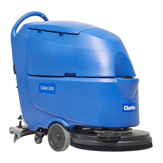
CA60 20D/CA60 20TD
CA60 20B/CA60 24B
SERVICE MANUAL
READ THIS BOOK
This book has important information for the use and safe operation of this machine. Failure to read this book prior to
operating or attempting any service or maintenance procedure to your Clarke machine could result in injury to you or
to other personnel; damage to the machine or to other property could occur as well. You must have training in the
operation of this machine before using it. If your operator(s) cannot read this manual, have it explained fully before
attempting to operate this machine.
All directions given in this book are as seen from the operator's position at the rear of the machine.
Advertisement
Table of Contents
Troubleshooting

Related Manuals for Clarke CA60 20B


Summary of Contents for Clarke CA60 20B
- Page 1 This book has important information for the use and safe operation of this machine. Failure to read this book prior to operating or attempting any service or maintenance procedure to your Clarke machine could result in injury to you or to other personnel;...
-
Page 2: Table Of Contents
Dimensions (Continues) ............................12 04 Control System ..............................15 Functional Description ............................15 Component LocationsFunction electronic board (E1) (CA60 20B/24B) .............. 16 Troubleshooting ..............................18 Control Panel Removal and Installation ......................19 Handlebar and drive switches disassembly/assembly (ES3) ................20 10 Chassis System .............................. -
Page 3: Table Of Contents
Functional Description ............................50 Component Locations ............................51 Troubleshooting ..............................53 Removal and Installation ............................. 54 Specifications ............................... 59 34 Scrub System, REV(CA60 20B/24B) ........................60 Functional Description ............................60 Component Locations ............................62 Troubleshooting ..............................64 Actuator Disassembly/Assembly ......................... 65 Maintenance and Adjustment .......................... -
Page 4: Service Manual
Service Manual-CA60 Table of Contents Maintenance and Adjustment ..........................76 Removal and Installation ............................. 80 Specifications ............................... 81 40 Recovery System..............................82 Functional Description ............................82 Component Locations ............................83 Maintenance and Adjustment ..........................84 Troubleshooting ..............................85 Removal and Installation ............................. 86 Specifications ............................... -
Page 5: 03 General Information
Other Reference Manuals Document name Document number Document type CA60 20B/ CA60 24B/ CA60 20D/ CA60 20TD, Instructions for Use Instructions for Use VS13039 These manuals are available at: – Local Clarke Retailer –... -
Page 6: Service And Spare Parts
Service Manual-CA60 03 General Information 3 Service and Spare Parts Service and repairs must be performed only by authorized personnel or Service Centers. The authorized personnel is trained directly at the manufacturer’s premises and has original spare parts and accessories. Contact Retailer indicated below for service or to order spare parts and accessories, specifying the ma-chine model and serial number. -
Page 7: Safety
Service Manual-CA60 03 General Information 4 Safety Symbols It is important for you to read and understand this manual. The information it contains relates to protecting your safety and preventing problems. The symbols below are used to help you recognize this information. Warning: Indicates a potentially hazardous situation which, if not avoided, could result in death or serious injury... -
Page 8: Machine Lifting
Service Manual-CA60 03 General Information 5 Property Damage Messages – Storage and operation temperature must be above 0° C and a humidity between 30% and 95%, non-condensing. – Before use, all doors and hoods should be properly latched. – This machine is not approved for use on public paths or roads. –... -
Page 9: Technical Data
Service Manual-CA60 03 General Information 6 Technical Data MODEL Units CA60 24B CA60 20B CA60 20D CA60 20TD Packing (1370x700x1300m (1370x600x1300mm)/ dimensions (Lx W mm/Inches m)/(54x28x52 (54x24x52 Inches) x H) Inches) Machine height mm/Inches 1080mm/42.5 Inches Machine length mm/Inches 1260mm/50 Inches... - Page 10 Service Manual-CA60 03 General Information 7 Handle Vibration m/S² Level(Max) Voltage Volts 24 Volts Battery(Optional) Amp/hour 105/130 WET, 105/140 AGM C20 Battery charger Volts/Amps 24 Volt/13 Amp Battery compartment size mm/Inches (350 x 350 x 300) mm / 13.8 x 13.8 x 11.8) Inches (L x W x H)
-
Page 11: Maintenance Schedule
Service Manual-CA60 03 General Information 8 Maintenance Schedule Procedure Daily, after use Weekly/ Monthly Every 6 Months Annually Charge Battery Clean squeegee blades Inspect pad/brush Clean solution and recovery tanks Inspect recovery tank seal Inspect squeegee blades for damage Clean the solution filter Inspect for loose fasteners and electrical connections Inspect/replace scrub motor brushes (battery model) 1 Also perform this inspection after the initial 10 hours of new machine usage. -
Page 12: Machine Nomenclature (Machine Structure)
Service Manual-CA60 03 General Information 9 Machine Nomenclature (machine structure) Recovery tank lid 20. Brush/pad-holder Can holder 21. Brush/pad-holder deck Handlebar 22. Recovery water drain hose Control panel 23. Solution tank Squeegee lifting/lowering lever 24. Hinge Garden coupling 25. Recovery tank Power supply cable holder 26. -
Page 13: Machine Nomenclature (Control Panel)
Service Manual-CA60 03 General Information 10 Machine Nomenclature (control panel) 36. Machine backward switch (B) 56. Speed adjuster (B) 37. Tank safety cable 57. Hour meter 58. • Brush/pad-holder release switch(only for disc 38. Battery connector (red). 39. Detergent tank filler plug (**) machine) •Extra pressure active(only for orbital machine) 40. -
Page 14: Service And Diagnostic Equipment
Service Manual-CA60 03 General Information 11 Service and Diagnostic Equipment Besides a complete set of standard meters, the following instruments are necessary to perform fast checks and repairs on machines: Laptop computer charged with the current version of EzParts, Adobe Reader and (if possible) Internet con- nection •... -
Page 15: Dimensions (Continues)
Service Manual-CA60 03 General Information 12 Dimensions (Continues) CA60 20D/CA60 20TD Figure 4... - Page 16 Service Manual-CA60 03 General Information 13 Dimensions (Continues) CA60 20B Figure 5...
- Page 17 Service Manual-CA60 03 General Information 14 Dimensions (Continues) CA60 24B Figure 6...
-
Page 18: Control System
Release brush (Only for CA60 20D and CA6020TD) Solution flow solenoid valve (EV1) Deck actuator (Only for CA60 20B / 24B) Detergent pump (Option M4) Battery type setting The main control board (E1) also shows the battery capacity by 3 LEDs, show the running time by LED digital display .The main control E1 can display the error message”LO-18”,if the battery voltage falls below 18 volts, and will display... -
Page 19: Component Locationsfunction Electronic Board (E1) (Ca60 20B/24B)
Service Manual-CA60 04 Control System Component LocationsFunction electronic board (E1) (CA60 20B/24B) • Signal circuit fuse 5A(F1) (CA60 20B/24B) • Brush actuator fuse 5A(F3) (CA60 20B/24B) • Battery capacity LEDs • LED digital display • Key switch Key switch Battery Capacity LEDS... - Page 20 Service Manual-CA60 04 Control System Component Locations(Continues) Function electronic board (E1) (CA60 20D/20TD) Signal circuit fuse 5A(F1) (CA60 20D/20TD) Brush release fuse 20A(F3) (CA60 20D/20TD) Function electronic board (E1) (CA60 20D/20TD) Brush release fuse 20A(F3) (CA60 20D/20TD) Signal circuit fuse 5A(F1) (CA60 20D/20TD) Figure 4...
-
Page 21: Troubleshooting
Service Manual-CA60 04 Control System Troubleshooting Trouble Possible causes Remedy The batteries (BAT) are discharged or its Charge the batteries or clean/repair the connections are not efficient connections Batteries faulty Check the battery no-load voltage Battery charger faulty Replace The machine is not working The fuses (F1, F2, F3) are open Replace The wiring harness is cut or pressed or... -
Page 22: Control Panel Removal And Installation
Service Manual-CA60 04 Control System Control Panel Removal and Installation Control panel and control electronic board disassembly/assembly (EB1) Disassembly Drain the recovery tank. Turn the ignition key to “0” and remove it. Make sure that the machine cannot move independently. Turn the recovery tank sideways, then disconnect the battery connector. -
Page 23: Handlebar And Drive Switches Disassembly/Assembly (Es3)
Service Manual-CA60 04 Control System Handlebar and drive switches disassembly/assembly (ES3) Disassembly Drain the recovery tank. Turn the ignition key to “0” and remove it. Make sure that the machine cannot move independently. Turn the recovery tank sideways, then disconnect the battery connector. Unscrew the screws (A) and carefully move the control panel (B). -
Page 24: 10 Chassis System
Service Manual-CA60 10 Chassis System 10 Chassis System Chassis(main parts) The chassis installed in the solution tank. The chassis is not the same for orbital machine (Figure 1) and disc machine (Figure 2). Figure 1 Figure 2... -
Page 25: 14 Wheel System, Traction
Service Manual-CA60 14 Wheel System 22 14 Wheel System, Traction Functional Description Machine movement is provided by the traction motor (M3) (except CA60 20D). The traction motor unit (M3) also functions as the main support of the machine, and is composed of an electric motor, the reduction unit with differential and the drive wheels. - Page 26 Service Manual-CA60 14 Wheel System 23 Wiring Diagram(CA60 20B/24B) Traction System Wiring Diagram (Only For CA60 20B/24B ) E2 Curtis 1210 E1 Main Control Board BAT+ Circuit Breaker 12A Power Supply+ J1-18 SPEED POT Power Supply- BAT- J1-3 POT HIGH...
-
Page 27: Component Locations
Service Manual-CA60 14 Wheel System 24 Component Locations • • Speed potentiometer(VR2) Traction motor controller curtis 1210(E2) • • Handle switches Traction Relay(K3) • • Reverse switch Traction circuit breaker (F3) Reverse switch Handle switches Speed potentiometer(VR2) Figure 3 Traction circuit breaker(F3) Traction relay(k3) Traction motor controller... - Page 28 Service Manual-CA60 14 Wheel System 25 Component Locations(Continues) Traction motor(M3) Rear pivoting wheel Driving wheel Traction motor(M3) Rear pivoting wheel Driving wheels Figure 5...
-
Page 29: Troubleshooting
Service Manual-CA60 14 Wheel System 26 Troubleshooting Trouble Possible causes Remedy Thermal fuse blown/broken Reset/Replace The machine does not move Turn the ignition key to “0”, then The machine has been started using the ignition key, keeping one of the switches restart the machine without pressing pressed. -
Page 30: Removal And Installation
Service Manual-CA60 14 Wheel System 27 Removal and Installation Drive System Motor Amperage Check Warning! This procedure must be performed by qualified personnel only. Drain the recovery tank. Drain the clean water tank. Drive onto a smooth, flat floor. Lift the squeegee. Lift the brush. - Page 31 Service Manual-CA60 14 Wheel System 28 Wheels Assembly with Drive System Motor disassembly/assembly (M3) Disassembly Drain the recovery tank. Drain the clean water tank. Remove the brush. Remove the squeegee. Remove the machine’s batteries. Remove the rear panel (see the procedure in the relevant paragraph). Disconnect the electrical connections (B) of the drive motor wiring from the drive system electronic board (A).
- Page 32 Service Manual-CA60 14 Wheel System 29 Wheels Assembly with Drive System Motor disassembly/assembly (M3) (Continues) Position a flattened cardboard box the same size as the machine’s side. With the assistance of a second person, turn the machine over sideways and rest its right-hand side on the box positioned on the floor.
- Page 33 Unscrew the screws (A) inside the wheel. Remove the outer cover (B) of the wheel. Unscrew the screw (C) and remove the wheel (D). Assembly 10. Assemble the components in the reverse order of disassembly. CA60 20B/24B CA60 20D/20TD Wheel for(CA60 20B/CA6024B) Figure 9...
- Page 34 Remove the outer cover (B) of the wheels. Unscrew the screws (C) and remove the wheels (D). Remove the drive motor. Assembly Assemble the components in the reverse order of disassembly. CA60 20B/24B CA60 20D/20TD Wheel for(CA60 20B/CA6024B) Figure 10...
-
Page 35: Specifications
Service Manual-CA60 14 Wheel System 32 Specifications Description/model CA60 20D CA60 20TD CA60 20B/CA60 24B Driving wheel diameter 8 in(202mm) Rear wheel diameter 3 in(76.2mm) Power 250W 150W Voltage Electric wheel drive unit Transmission ratio 16:1 technical data Protection class... -
Page 36: 24 Electrical System
CA60 Electrical Battery Charger Wire Diagram E1 Main Control Board BAT1 J2-3 J1-15 Charger IN J1-9 +24V GRN YEL J1-7 Battery Charger Key Switch J1-5 J1-4 J1-3 RD/BK RD/BK Signal Cicuit Fuse Brush Actuator Fuse(For CA60 20B/24B) Brush Release Fuse(For CA60 20D/20TD) Figure 1... - Page 37 Service Manual-CA60 24-Electrical System Setting the Installed Battery According to the type of batteries (WET OR GEL/AGM) ,set the machine as follows. 1. Press both the buttons (A, Figure. 2) and (B) at the same. Insert the ignition key (D) and turn on the power, after 0.5 second, the LED display (C) ,will show the current battery type saved in memory to confirm that you are in the battery setting mode.
-
Page 38: Component Locationsbattery Charger (Ch1)
Service Manual-CA60 24-Electrical System Component LocationsBattery Charger (CH1) Batteries(BAT1) Brush Circuit Breaker(F1) 4-way signal connection(J1) Vacuum Circuit Breaker(F2) Battery Connector(C1) Traction Circuit Breaker(F3) (only CA60 20B/24B/20TD) 4-way signal connection(J1) Battery Charger(CH1) Vacuum Circuit Breaker (F2) Brush Circuit Breaker (F1) Traction Circuit Breaker(F3) Figure 3... - Page 39 Service Manual-CA60 24-Electrical System Wiring Diagram (CA60 20B/24B) BAT1 E1 Main Control Board E2 Curtis 1210 (A) TO 1D1 J2-3 Circuit Breaker 17A J1-18 SPEED POT J1-15 Charger IN GN/BK GN/BK J1-3 J1-9 +24V POT HIGH TO 1C3 GN/BK GN/BK...
- Page 40 Service Manual-CA60 24-Electrical System Wiring Diagram (CA60 20TD) BAT1 E1 Main Control Board E2 Curtis 1210 (A) TO 1D1 J2-3 Circuit Breaker 12A J1-18 SPEED POT J1-15 Charger IN GN/BK GN/BK J1-3 J1-9 POT HIGH +24V TO 1C3 GN/BK GRN YEL GN/BK J1-7 J1-5...
- Page 41 Service Manual-CA60 24-Electrical System Wiring Diagram (CA60 20D) BAT1 E1 Main Control Board J2-3 J1-15 Charger IN J1-9 +24V J1-7 Battery Charger Key Switch J1-5 J1-4 J6-1 C2 WHI J1-3 J6-2 Detergent ADJ 100K J6-3 RD/BK RD/BK OPTION J1-2 +24V J2-1 +24V J1-3...
-
Page 42: Removal And Installation
Service Manual-CA60 24-Electrical System Removal and Installation Rear panel disassembly/assembly Disassembly Drain the recovery tank. Turn the ignition key to “0” and remove it. Make sure that the machine cannot move independently. Turn the recovery tank sideways, then disconnect the battery connector. Lower the squeegee (A) with the lever (B). - Page 43 Service Manual-CA60 24-Electrical System Drive system electronic board disassembly/assembly Disassembly Remove the rear panel (see the procedure in the relevant paragraph). Disconnect the electrical connections (A) on the drive system electronic board (B), then move the wiring out of the way. Unscrew the two screws (C) and remove the drive system electronic board (B).
- Page 44 Service Manual-CA60 24-Electrical System Battery charger disassembly/assembly Disassembly Drain the recovery tank. Turn the ignition key to “0” and remove it. Make sure that the machine cannot move independently. Turn the recovery tank sideways, then disconnect the battery connector. Disconnect the terminals of the right-hand battery (A), then remove it using suitable lifting equipment. Unscrew the screws (B) and disconnect the battery connector (C).
- Page 45 (F4), rated 12 A, for protection of the drive motor (*CA60 20D/CA60 20TD) fuse (F4), rated 17 A, for protection of the drive motor (*CA60 20B/CA60 24B) • (G): fuse (F2), rated 30 A, for protection of the brush rotation motor...
-
Page 46: Solution System
Brush function on One of the two handle switches is pressed Battery level not in condition with flashing segment Wiring Diagram(CA60 20B/24B) lution System Wiring Diagram (20B/24B ) E1 Main Control Board J2-6 +24V C10a Power Supply+... - Page 47 Service Manual-CA60 30 Solution System 44 Wiring Diagram(CA60 20D/20TD) olution System Wiring Diagram (20D/20TD ) E1 Main Control Board J2-1 +24V C10a Power Supply+ J2-5 Solution Valve C10b J2-2 +24V Power Supply- C11a J2-6 Detergent Pump C11b OPTION Figure 2...
-
Page 48: Component Locations
Service Manual-CA60 30 Solution System 45 Component Locations Solution valve(EV1) Detergent pump(M4) EcoFlex detergent tank Detergent pump(M4) EcoFlex detergent tank Figure 3 Solution valve(EV1) Figure 4... -
Page 49: Maintenance And Adjustment
Service Manual-CA60 30 Solution System 46 Maintenance and Adjustment Solution filter cleaning Drive the machine on a level floor. 2. Ensure that the machine is off and the ignition key has been removed. 3. Close the solution tap (A, Figure. 5) under the machine, behind the right rear wheel. -
Page 50: Troubleshooting
Service Manual-CA60 30 Solution System 47 Troubleshooting Possible causes Trouble Remedy The solution filter is clogged/dirt Clean Solenoid valve faulty or electrical Replace the solenoid valve or repair the Small amount of solution or no connection broken electrical connection solution reaches the brush There is dust/debris in the tank or in the Clean the tank/hoses detergent hoses, obstructing the solution... -
Page 51: Removal And Installation
Service Manual-CA60 30 Solution System 48 Removal and Installation Solenoid Valve Disassembly/Assembly (M4) Disassembly Remove the wheels assembly with drive system motor (see the procedure in the relevant paragraph). Loosen the clamps (A) and disconnect the hoses (B) from the solenoid valve (C). Unscrew the screws (D) and move the solenoid valve (C). -
Page 52: Specifications
Service Manual-CA60 30 Solution System 49 Specifications Description/model CA60 20D/CA60 20TD CA60 20B/CA60 24B Solution tank capacity 61 L 61 L (0.4/0.8/1.4/2.2) Liters (0.7/1.2/1.7/2.2) Liters Solution flow values (0.11/0.21/0.37/0.6) Gallons (0.2/0.3/0.45/0.6) Gallons Solution Solenoid Coil Resistance 120Ω @25℃... -
Page 53: Scrub System, Disc (Ca60 20D/20Td)
Service Manual-CA60 34 Scrub System DISC(CA60 20D/20TD) 50 34 Scrub System, Disc (CA60 20D/20TD) Functional Description The disc brush system can be started by the operator. To work properly, the brush motor (M1) needs the fol- The disc brush turns counter-clockwise. lowing: ... -
Page 54: Component Locations
Service Manual-CA60 34 Scrub System DISC(CA60 20D/20TD) 51 Component Locations Brush motor(M1) Brush contractor Disc brush deck Brush circuit breaker 30A(F1) Brush Brush motor(M1) Disc brush deck Brush Figure 2 Brush circuit breaker 30A(F1) Brush contractor Figure 3... - Page 55 Service Manual-CA60 34 Scrub System DISC(CA60 20D/20TD) 52 Component Locations(continues) Brush release relay(K1) Brush release fuse 20A(F3) Brush release fuse Brush release relay(K1) 20A(F3) Figure 4...
-
Page 56: Troubleshooting
Service Manual-CA60 34 Scrub System DISC(CA60 20D/20TD) 53 Troubleshooting Possible causes Trouble Remedy The brush does not clean properly The brush is excessively worn Replace The batteries are discharged. Charge them The motor carbon brushes are worn Replace The motor is faulty Check the motor amperage/replace the motor There are ropes or debris restraining the... -
Page 57: Removal And Installation
Service Manual-CA60 34 Scrub System DISC(CA60 20D/20TD) 54 Removal and Installation Brush Motor Amperage Check Warning! This procedure must be performed by qualified personnel only. Drain the recovery tank. Remove the brush. Make sure that the machine cannot move independently. Turn the recovery tank (A) sideways. - Page 58 Service Manual-CA60 34 Scrub System DISC(CA60 20D/20TD) 55 Brush Deck Disassembly/Assembly Disassembly Drain the recovery tank. Drain the clean water tank. Remove the brush. Remove the squeegee. Remove the machine’s batteries. Position a flattened cardboard box the same size as the machine’s side. With the assistance of a second person, turn the machine over sideways and rest its right-hand side on the box positioned on the floor.
- Page 59 Service Manual-CA60 34 Scrub System DISC(CA60 20D/20TD) 56 Brush Deck Disassembly/Assembly (Continues) Mark the position of the nut (E) with respect to the threaded tie rod (F) of the spring (G) (position to be used during reassembly). 10. Unscrew the nut (E), then disconnect the tie rod (F) from the support (S). 11.
- Page 60 Service Manual-CA60 34 Scrub System DISC(CA60 20D/20TD) 57 Brush Motor Carbon Brushes Disassembly/Assembly Disassembly Remove the brush deck (see procedure in the relevant paragraph); it is not necessary to disconnect the brush motor electrical connection. Unscrew the screws (A) and remove the brush motor (C) protection strip (B). For each of the motor’s four carbon brushes, disengage the spring (D) and remove the carbon brush (E) from its seat, then detach the carbon brush by disengaging its electrical connection (F).
- Page 61 Service Manual-CA60 34 Scrub System DISC(CA60 20D/20TD) 58 Brush Motor Disassembly/Assembly (M1) Disassembly Remove the brush deck (see procedure in the relevant paragraph). Unscrew the screw (A) and remove the brush hub (B), along with the flange. Remove the brush motor (D) fastening screws (C). Remove the brush motor (D) from the brush deck (E).
-
Page 62: Specifications
Service Manual-CA60 34 Scrub System DISC(CA60 20D/20TD) 59 Specifications Description/model CA60 20D CA60 20TD 21in(530mm) Cleaning width 60lb(27KG) 51lb(23KG) Pressure 450W motor power 150RPM Rotation speed Insulation class 110Ω Brush Contactor Coil Resistance @25℃... -
Page 63: Scrub System, Rev(Ca60 20B/24B)
Brush function on One of the two handle switches is pressed Battery level not in critical condition with flashing segment Wiring Diagram Scrub System Boost Wiring Diagram (CA60 20B/CA60 24B ) BAT1 Power Supply+ E1 Main Control Board J1-2 +24V... - Page 64 Service Manual-CA60 34 Scrub System REV (CA60 20B/24B) 61 Brush Deck Actuator Function (only for CA60 20B/24B) The brush deck actuator of CA60 is controlled directly by the main control board without extra electromechanical limit switches or position switches, The actuator does not require adjustment. The controller learns the position of the actuator by watching for when the motor amperage draw increases when it comes to a mechanical stop at the top of its travel.
-
Page 65: Component Locations
Service Manual-CA60 34 Scrub System REV (CA60 20B/24B) 62 Component Locations REV motor(M1) Brush deck REV Brush deck Actuator(M5) REV pad REV motor(M1) Brush deck REV REV PAD Figure 1 Brush deck actuator(M5) Figure 2... - Page 66 Service Manual-CA60 34 Scrub System REV (CA60 20B/24B) 63 Component locations (continue) Brush contactor Brush circuit breaker 30A (F1) Brush contactor Brush circuit breaker 30A(F1) Figure 3...
-
Page 67: Troubleshooting
Service Manual-CA60 34 Scrub System REV (CA60 20B/24B) 64 Troubleshooting Trouble Possible causes Remedy The batteries (BAT) are discharged or its Charge the batteries or clean/repair the connections are not efficient connections Batteries faulty Check the battery no-load voltage Actuator gear broken... -
Page 68: Actuator Disassembly/Assembly
Service Manual-CA60 34 Scrub System REV (CA60 20B/24B) 65 Actuator Disassembly/Assembly Disassembly Turn the ignition key (A) to “I” and press the button (B). Lowering the orbital head. remove the ignition key (A). Unscrew the screws (C). Remove the key (D) and pin(E). -
Page 69: Maintenance And Adjustment
Service Manual-CA60 34 Scrub System REV (CA60 20B/24B) Maintenance and Adjustment Adjusting the level of orbital deck (only for orbital machine) 1. Lower the brush/pad-holder deck by press the brush/ pad holder switch (M, Figure. 9) 2. Adjust the level of orbital deck by adjusting handle (A, Figure 9.1) . made the bubble in the middle (B, Figure 9.1). -
Page 70: Troubleshooting
Service Manual-CA60 34 Scrub System REV (CA60 20B/24B) Troubleshooting Trouble Possible causes Remedy The batteries (BAT) are discharged or its Charge the batteries or clean/repair the connections are not efficient connections Batteries faulty Check the battery no-load voltage Battery charger faulty... -
Page 71: Orbital Deck Disassembly/Assembly
Service Manual-CA60 34 Scrub System REV (CA60 20B/24B) 68 Orbital deck Disassembly/Assembly Disassembly Turn the ignition key (A) to “I” and press the button (B). Lowering the orbital head. remove the ignition key (A). Unscrew the screws (E). Loosen the clamp (D) and disconnect the water hose (C) from the deck. - Page 72 Service Manual-CA60 34 Scrub System REV (CA60 20B/24B) 69 ( ) Orbital deck Disassembly/Assembly Continues Unscrew the bumper roller(H) screws. The weight block screws (I). The plate head deck screws(G).Remove it. Unscrew the screws(K). Turn over the orbital deck, Unscrew the screws(P). Take out the flex plate(Q)
- Page 73 Service Manual-CA60 34 Scrub System REV (CA60 20B/24B) 70 ( ) Orbital deck Disassembly/Assembly Continues Unscrew the screws(M). Unscrew the screws(N). Use three-jaw catch the driver plate(O) and take out it. Remove the orbital motor fastening screws (P). Assembly 12.Assemble the components in the reverse order of disassembly, and note the following. Position the orbital motor in the position (X) shown in the figure.
-
Page 74: Checking/Replacing Rev Motor Carbon Brushes
Service Manual-CA60 34 Scrub System REV (CA60 20B/24B) 71 Checking/Replacing REV Motor Carbon Brushes Place the motor on a workbench. Remove four screws (A). Remove the cover of motor(B). Replace the carbon brushes. Remove the screws (D) and replace the carbon brushes(C). -
Page 75: Specifications
Service Manual-CA60 34 Scrub System REV (CA60 20B/24B) 72 Specifications Description/model CA60 20B CA60 24B 20in(508mm) REV Cleaning width 24in(609mm) 89lb(40KG) First Stage Pressure 110lb(50KG) Second Stage Pressure 5 in (125 mm) Brush distance from the floor (when lifted) 750W... -
Page 76: 38 Squeegee System
Service Manual-CA60 38 Squeegee System 73 38 Squeegee System Functional Description The squeegee system cleans the liquid off the floor, which is then collected by the recovery system. The squeegee is mounted on castors and the weight of the system presses it down on the floor. The squeegee is attached with two quick-fastening handwheels which fit in the slots of the squeegee support. -
Page 77: Component Locations
Service Manual-CA60 38 Squeegee System 74 Component Locations Squeegee lifting/lowering lever Mounting handwheels Impact deflection wheel Squeegee blades Squeegee lifting/lowering Impact deflection wheels lever Mounting handwheels Squeegee blades Figure 1... -
Page 78: Troubleshooting
Service Manual-CA60 38 Squeegee System 75 Troubleshooting Possible causes Trouble Remedy The recovery water vacuuming is The squeegee or the vacuum hose is Clean or repair/replace insufficient or there is no vacuuming clogged or damaged There is debris under the blade Remove The squeegee blade edges are torn or Replace... -
Page 79: Maintenance And Adjustment
Service Manual-CA60 38 Squeegee System (CA60 20B/24B) 76 Maintenance and Adjustment Squeegee Blade Changing The two squeegee blades periodically need to be changed as they wear. The blades may be flipped or reversed to a fresh edge up to 3 times before replacement is required. During replacement, it is important for the blades to be installed flat without waves, and then also adjusted to rest flat against the floor. - Page 80 Service Manual-CA60 38 Squeegee System (CA60 20B/24B) 77 Pull out on the latch (D) to release the tension on the retaining strap. Separate the retaining hooks (E) from the two halves of the retaining strap. Slide each retaining strap (G) toward the outside, and lift them off the edge retaining hooks (H).
- Page 81 Service Manual-CA60 38 Squeegee System (CA60 20B/24B) 78 11. Loosen the clamping thumbscrew (P) on the rear strap (L), and remove the strap from the frame. 12. Remove the rear squeegee blade. – The squeegee can be rotated and/or flipped 3 times to expose a new edge (4 edges total) to the lower front.
- Page 82 Service Manual-CA60 38 Squeegee System (CA60 20B/24B) 79 Squeegee Trim Adjustment The squeegee trim adjustment ensures that the squeegee frame is level with the floor when the squeegee is in the lowered, operating position. If the trim is out of adjustment, the squeegee can leave streaks of water at either the center or the edges of the squeegee.
-
Page 83: Removal And Installation
Service Manual-CA60 38 Squeegee System (CA60 20B/24B) 80 Removal and Installation Squeegee spring disassembly/assembly Disassembly Drain the recovery tank. Drain the clean water tank. Remove the brush. Remove the squeegee. Remove the machine’s batteries. Position a flattened cardboard box the same size as the machine’s side. With the assistance of a second person, turn the machine over sideways and rest its right-hand side on the box positioned on the floor. -
Page 84: Specifications
Service Manual-CA60 38 Squeegee System (CA60 20B/24B) 81 Specifications Description/model CA60 20D/CA60 20TD CA60 20B/CA60 24B Squeegee width 29.9 in (760mm) -
Page 85: 40 Recovery System
Battery level not in critical condition with flashing segments. When turn off the vacuum motor, the vacuum LED on dashboard will flash 5 seconds, then disable the vacuum motor. Wiring Diagram Recovery System Wiring Diagram (CA60 20B/24B/20D/20TD ) BAT1 E1 Main Control Board Power Supply+ Power Supply-... -
Page 86: Component Locations
Service Manual-CA60 40 Recovery System 83 Component Locations • • Vacuum motor(M2) Vacuum relay (K2) • • Squeegee vacuum hose Vacuum Circuit Breaker 30A (F2) • Recovery water drain hose Vacuum motor(M2) Recovery water drain hose Squeegee vacuum hose Figure 2 Vacuum relay (K2) Vacuum circuit breaker 30A(F2) -
Page 87: Maintenance And Adjustment
Service Manual-CA60 40 Recovery System 84 Maintenance and Adjustment Drive the machine on a level floor. 2. Ensure that the machine is off and the ignition key has been removed. 3. Turn the recovery tank lid (A, Figure 4) 90 degree position where it can be took off from the tank, and then take down the float ball filter (P) from the tank. -
Page 88: Troubleshooting
Service Manual-CA60 40 Recovery System 85 Troubleshooting Trouble Possible causes Remedy The switch is broken Replace The vacuum system motor is faulty Check the amperage. The vacuum system motor does not turn The fuse is blown Replace. The recovery tank is full Drain the recovery tank The vacuum hose is disconnected from Connect. -
Page 89: Removal And Installation
Service Manual-CA60 40 Recovery System 86 Removal and Installation Vacuum System Amperage Check Warning! This procedure must be performed by qualified personnel only. Drain the recovery tank. Make sure that the machine cannot move independently. Turn the recovery tank (A) sideways. Apply the amp clamp on the cable from the positive pole of the batteries (B). - Page 90 Service Manual-CA60 40 Recovery System 87 Vacuum System Motor disassembly/assembly (M2) Disassembly Drain the recovery tank. Turn the ignition key to “0” and remove it. Make sure that the machine cannot move independently. Turn the recovery tank sideways, then disconnect the battery connector. Working from the bottom of the recovery tank, unscrew the screws (A) and remove the vacuum motor retention plate (B).
-
Page 91: Specifications
Service Manual-CA60 40 Recovery System 88 Specifications Description/model CA60 20D/CA60 20TD CA60 20B/CA60 24B Recovery tank capacity 0.47 hp (350W) Vacuum motor technical data A VDC 24V Vacuum circuit capacity 47.2 in H2O (1200 mm H2O) Vacuum Relay Coil Resistance @25℃...