
Related Manuals for Fluke DSX-600


Summary of Contents for Fluke DSX-600
- Page 1 DSX-600 CableAnalyzer ™ Technical Reference Handbook Software Version 5.2 May 2017, Rev. 1 8/2017 ©2017 Fluke Corporation All product names are trademarks of their respective companies.
- Page 2 LIMITED WARRANTY AND LIMITATION OF LIABILITY Each Fluke Networks product is warranted to be free from defects in material and workmanship under normal use and service unless stated otherwise herein. The warranty period for the mainframe is one year and begins on the date of purchase.
-
Page 3: Table Of Contents
Contents Chapter 1 Get Acquainted Overview of Features ............1 Contact Fluke Networks ..........2 Register Your Product ............2 Additional Resources ............2 Supplements and Updated Manuals ......2 Symbols ................3 Safety Information ............4 Connectors, Keys, and LEDs ..........8 About Link Interface Adapters ........12 How to Prevent Damage to the Adapter Cables ................12... - Page 4 Tutorial: Make a Set of Sequential Cable IDs ..40 About Projects ..............41 Chapter 3 Certify Twisted Pair Cabling The DSX-600 CableAnalyzer Home Screen ....43 Make Sure Your Tester is Ready to Certify Twisted Pair Cabling ............47...
- Page 5 Contents Set the Reference ............48 Settings for Twisted Pair Tests ........49 How to Do an Autotest ..........54 “Bad Patch Cord” Message ..........57 Twisted Pair Autotest Results .........58 PASS*/FAIL* Results ..........58 WIRE MAP Tab ............59 PERFORMANCE Tab ..........64 Scalar Results ............65 Length, Propagation Delay, and Delay Skew..65 Loop Resistance ..........67 Continuous Tests ............70...
- Page 6 DSX-600 CableAnalyzer Technical Reference Handbook 12 dB Rule ............92 67 dB Rule for ACR-F and PS ACR-F ....92 70 dB Rule for ACR-F and PS ACR-F ....92 How to Use the Tone Generator ........94 How to Use the Talk Function ........95...
- Page 7 Contents How to Use the Measurement Cursor on the HDTDR and HDTDX Plot ..........137 Chapter 7 Manage Test Results View Saved Results ............141 How to Replace a Saved Result that Failed ....144 Delete, Rename, and Move Results .......144 Manage Results on a Flash Drive ........146 Upload Results to a PC ............147 About LinkWare Live ............148 View the Memory Status ..........149...
- Page 8 DSX-600 CableAnalyzer Technical Reference Handbook To Change the ID ............. 162 To use a different, unused ID from an ID set that has a first and last ID ....162 To use an ID you used before ......163 To use an ID that is not in an ID set that has a first and last ID .........
- Page 9 Contents Use LinkWare Live Through a Wired Ethernet Network ................174 Use LinkWare Live Through a Wi-Fi Ethernet Network ................175 Change the Network Settings ........178 Settings for the Wired Port ........178 Settings for the Wi-Fi Port ........179 Delete Wi-Fi Settings and Passwords ......179 About the Asset Management Service ......179 Sign Your Tester Out of LinkWare Live ......179 Sign In to LinkWare Live from a Desktop or...
- Page 10 DSX-600 CableAnalyzer Technical Reference Handbook Use an Updated Main Tester to Update Other Testers ............... 194 Use LinkWare Live to Update the Software ... 196 Extend the Life of the Battery ........197 Store the Tester .............. 197 Remove the Battery ............197 Replace the Tip on a DSX-PLA004 Connector ....
- Page 11 Contents HDTDR Analyzer Specifications for Cables <100 m (328 ft) ..........210 Characteristic Impedance .........210 Tone Generator ............210 Input Protection ............211 Power ................211 Traceable Calibration Period ..........211 DSX-CHA003 Coaxial Adapter ........212 Internal Memory for Test Results ........213 USB Flash Drive ...............213 Serial Interfaces ...............213 RJ45 Connector on the Main Unit .........213 Headset Jack ..............213...
- Page 12 DSX-600 CableAnalyzer Technical Reference Handbook...
-
Page 13: List Of Figures
Examples of Twisted Pair Autotest Results Screens .....35 FIX LATER, TEST AGAIN, and TEST Buttons and the TEST Key..............36 The Home Screen for DSX-600 CableAnalyzer .....44 Reference Connections for Twisted Pair Cable ....49 Outlet Configurations............53 Equipment for Autotests on Twisted Pair Cable ....54 Permanent Link Connections..........56... - Page 14 DSX-600 CableAnalyzer Technical Reference Handbook Wire Map Examples: Open Wire and Open Shield ....61 Wire Map Examples: Short and Split Pair......62 Wire Map Examples: Reversed Pair and Crossed Pairs..63 PERFORMANCE Tab ............... 64 Twisted Pair Length Results ..........67 Twisted Pair Resistance Results ..........
- Page 15 List of Figures Reference Connections for Tests on Coaxial Cabling...104 Equipment for Tests on Coaxial Cabling.......108 Examples of Connections for Tests on Coaxial Cabling ..109 Autotest Results for Coaxial Cabling ........110 Coaxial Length and Propagation Delay Results ....112 Coaxial Resistance Results............113 Coaxial Impedance Results ............115 Coaxial Insertion Loss Results ..........116 Connections for Coaxial Tests Without a Remote....119...
- Page 16 DSX-600 CableAnalyzer Technical Reference Handbook How to Replace the DSX-PLA004 Adapter’s Tip and Latch ..................199 Plug for the Headset Jack ............. 214...
- Page 17 List of Tables Table Page Symbols ...................3 Settings for Twisted Pair Tests..........50 dB Rules for TIA Test Limits ...........93 dB Rules for ISO Test Limits ...........93 Settings for Coaxial Tests............106 Remote Requirements for Coaxial Tests .......118 Causes of Twisted Pair Test Failures........121 Causes of Coaxial Test Failures ..........125 Settings for the Wi-Fi Connection.........180 Possible Solutions for Unusual Behavior ......200...
- Page 18 DSX-600 CableAnalyzer Technical Reference Handbook...
-
Page 19: Chapter 1 Get Acquainted
Chapter 1: Get Acquainted Overview of Features The DSX-600 CableAnalyzer main and remote units are rugged, hand-held instruments that you configure to certify, troubleshoot, and document copper cabling. The DSX-600 includes these features: The testers certify twisted pair cabling to Cat 6A/Class E ... -
Page 20: Contact Fluke Networks
Fluke Networks operates in more than 50 countries worldwide. For more contact information, go to our website. Register Your Product Registering your product with Fluke Networks gives you access to valuable information on product updates, troubleshooting tips, and other support services. If you purchased a Gold Support plan, registration also activates your plan. -
Page 21: Symbols
This Product contains a lithium-ion battery. Do not mix with the solid waste stream. Spent batteries should be disposed of by a qualified recycler or hazardous materials handler per local regulations. Contact your authorized Fluke Service Center for recycling information. Complies with California Energy Commission (CEC) requirements ... -
Page 22: Wsafety Information
DSX-600 CableAnalyzer Technical Reference Handbook Table 1. Symbols (continued) 40 year Environment Friendly Use Period (EFUP) under China Regulation - Administrative Measure on the Control of Pollution Caused by Electronic Information Products. This is the period of time before any of the identified hazardous substances are likely to leak out, causing possible harm to health and the environment. - Page 23 Chapter 1: Get Acquainted WSafety Information Do not use the Product around explosive gas, vapor, or in damp or wet environments. Use this Product indoors only. Use the Product only as specified, or the protection supplied by the Product can be compromised. Do not use and disable the Product if it is damaged.
- Page 24 Do not put in direct sunlight. Have an approved technician repair the Product. Use only AC adapters approved by Fluke Networks for use with the Product to supply power to the Product and charge the battery.
- Page 25 You can lose a USB flash drive, cause damage to it, or accidentally erase the contents of the drive. Thus, Fluke Networks recommends that you save no more than one day of test results on a flash drive, or that you upload results to LinkWare Live. See Chapter 9.
-
Page 26: Connectors, Keys, And Leds
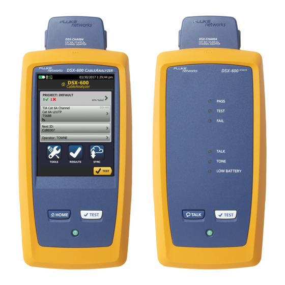
DSX-600 CableAnalyzer Technical Reference Handbook Connectors, Keys, and LEDs BA88.EPS Figure 1. Main Tester Connectors, Keys, and LEDs Connector for a link interface adapter LCD display with touchscreen : Starts a test. To start a test, you can also tap TEST on the display. - Page 27 The LED is yellow if the battery will not charge. See “Charge the Battery” on page 16. RJ45 connector: Lets you connect to a network for access to Fluke Networks cloud services.
- Page 28 DSX-600 CableAnalyzer Technical Reference Handbook BA42.EPS Figure 2. Remote Tester Connectors, Keys, and LEDs Connector for a link interface adapter ...
- Page 29 Chapter 1: Get Acquainted Connectors, Keys, and LEDs PASS LED comes on when a test passes. TEST LED flashes during a test. FAIL LED comes on when a test fails. TALK LED comes on when the talk function is on ( ).
-
Page 30: About Link Interface Adapters
DSX-600 CableAnalyzer Technical Reference Handbook About Link Interface Adapters Link interface adapters let you connect the DSX CableAnalyzer to different types of twisted pair links. Figure 3 shows how to attach and remove adapters. BA109.EPS Figure 3. How to Attach and Remove Link Interface Adapters... - Page 31 Chapter 1: Get Acquainted About Link Interface Adapters 5 in (13 cm) minimum GPU108.EPS Figure 4. How to Prevent Damage to the Permanent Link Adapter Cables...
-
Page 32: About The Optional Dsx-Pla001 Adapter Modules
DSX-600 CableAnalyzer Technical Reference Handbook About the Optional DSX-PLA001 Adapter Modules The optional DSX-PLA001 Universal Permanent Link Adapter has an interchangeable personality module. The module lets you connect the adapter to different styles of insulation displacement connectors (IDCs). Figure 5 shows how to remove and install a personality module. - Page 33 Chapter 1: Get Acquainted About Link Interface Adapters BA164.EPS Figure 5. How to Change the Personality Module on an Optional DSX-PLA001 Adapter...
-
Page 34: Ac Adapter And Battery
DSX-600 CableAnalyzer Technical Reference Handbook AC Adapter and Battery You can use the ac adapter (model PWR-SPLY-30W) or the lithium ion battery (model VERSIV-BATTERY) to supply power to the tester. To remove the battery, see “Remove the Battery” on page 197. -
Page 35: Check The Battery Status
Chapter 1: Get Acquainted AC Adapter and Battery Check the Battery Status On a main tester The battery status icon is in the upper-left corner of the screen: Battery is full. Battery is approximately half full. If the ac adapter is not connected, the red bar shows that the battery is very low. - Page 36 When the ac adapter is not connected, the screen shows the Time Remaining, which is the approximate battery life at the present rate of use. DSX-600 with two channel adapters and a patch cord DSX-600 with permanent link and channel adapters BA148.EPS...
-
Page 37: Verify Operation
Operate as Usual” on page 200. How to Use the Touchscreen The DSX-600 main unit’s Taptive user interface lets you use a touchscreen to control the tester. You can operate the touchscreen with your fingertip or with a stylus that is made for projected capacitance touchscreens. - Page 38 DSX-600 CableAnalyzer Technical Reference Handbook When you zoom a plot, horizontal and vertical zoom controls show on the screen. These controls let you change the magnification on the distance and decibels scales independently. You can zoom in to a maximum magnification factor of 128:1.
- Page 39 Chapter 1: Get Acquainted How to Use the Touchscreen To move the image, drag it in To zoom in, use the reverse- any direction. pinch gesture To quickly go back to 1:1 To zoom out, use the pinch magnification, double-tap the gesture screen.
-
Page 40: How To Enter Text
DSX-600 CableAnalyzer Technical Reference Handbook How to Enter Text When you tap a panel to enter text, a keyboard shows on the bottom half of the display (Figure 9). To enter characters, tap the characters on the keyboard. ... - Page 41 Chapter 1: Get Acquainted How to Enter Text Standard characters Accented letters Keyboard to sign in to your LinkWare Live TOOLS Sign account ( > GPU28.EPS Figure 9. The Keyboards for Text Entry...
-
Page 42: Set User Preferences
DSX-600 CableAnalyzer Technical Reference Handbook Set User Preferences User preferences are settings you usually change when you use the tester for the first time. Note You can use LinkWare PC software to make a file that contains settings for user preferences, then you can install the settings in one or more testers. -
Page 43: Number Format
Tap a time. To always keep the backlight or tester on, tap Disabled. To go back to the home screen, tap two times or press . The DSX-600 remote tester turns off after 60 minutes of inactivity. You cannot change this setting. -
Page 44: Audible Tone
DSX-600 CableAnalyzer Technical Reference Handbook Audible Tone You can enable or disable the tones the tester makes during tests and when you press keys. If you connect a remote tester to the main tester, the remote uses the main tester’s setting. -
Page 45: Import User Preferences From A File
Overview of Memory Functions You can save approximately 12,700 Cat 6A Autotest results, with plot data included, in the DSX-600 main tester. The capacity available for test results depends on the space used by the software and custom test limits in the tester. -
Page 46: How To Install A Strap
Technical Reference Handbook How to Install a Strap The DSX-600 includes a carrying strap that lets you carry and hang the tester. A hand strap that helps you hold the tester is also available. You can purchase a hand strap from an authorized Fluke Networks distributor. -
Page 47: About Linkware Applications
PC, organize and examine test results, print professional-quality test reports, and do software updates and other maintenance procedures on your tester. You can download LinkWare PC from the Fluke Networks website. The LinkWare Live Web Application... - Page 48 DSX-600 CableAnalyzer Technical Reference Handbook...
-
Page 49: Chapter 2 Get Started
Figure 11 shows the minimum equipment necessary for this tutorial. AQ101.EPS Main and remote DSX-600 units Twisted pair cable Two channel adapters AC adapters with line cords (optional) -
Page 50: Step 1: See How Much Memory Is Available
DSX-600 CableAnalyzer Technical Reference Handbook Step 1: See How Much Memory is Available On the home screen, tap the TOOLS icon, then tap Memory Status. The MEMORY STATUS screen shows these values: The percentage of memory available The number of test records that are saved ... - Page 51 Chapter 2: Get Started Tutorial: Certify Twisted Pair Cabling Test Limit: The test limit specifies the limits for measurements so that the tester can give a PASS or FAIL result to the test. The TEST LIMIT screen shows the last 10 limits that were selected.
-
Page 52: Step 3: Turn Off The Auto Save Function
DSX-600 CableAnalyzer Technical Reference Handbook Step 3: Turn Off the Auto Save Function For this tutorial, you will manually save the test results. On the home screen, tap the Next ID panel. On the CHANGE ID screen, tap the Auto Save control to make it show Off. - Page 53 Chapter 2: Get Started Tutorial: Certify Twisted Pair Cabling BA103.EPS Figure 12. Examples of Twisted Pair Autotest Results Screens...
-
Page 54: Step 6: Save The Results
DSX-600 CableAnalyzer Technical Reference Handbook Step 6: Save the Results Tap SAVE (if the result was PASS) or FIX LATER (if the result was FAIL). On the SAVE RESULT screen, tap the Cable ID box, use the keyboard to enter an ID for the results, then tap DONE. - Page 55 Chapter 2: Get Started Buttons to Do Tests and Save Results SAVE (yellow), TEST (gray): These buttons show if the test passed and Auto Save is off. When you tap SAVE, you can save the results with an ID that you make or select. When you tap TEST, you can select to save the results or do the test again and not save the results.
-
Page 56: Options For Cable Ids
DSX-600 CableAnalyzer Technical Reference Handbook Options for Cable IDs When you save the test results for a cable, you usually give the results the name that is the ID for the cable. There are several methods you can use to make IDs for test results: ... -
Page 57: Automatic Increment Function For Cable Ids
Chapter 2: Get Started Options for Cable IDs Automatic Increment Function for Cable IDs Each time you save a result, the tester automatically saves the result with the next ID in the set. It is not necessary for the IDs in a set to be sequential. -
Page 58: Tutorial: Make A Set Of Sequential Cable Ids
DSX-600 CableAnalyzer Technical Reference Handbook If Auto Save is on and the test failed: To saved the failed result before you do a test for the next ID, tap FIX LATER. To do the test again for the same ID, tap TEST AGAIN. -
Page 59: About Projects
Chapter 2: Get Started About Projects On the home screen, tap the PROJECT panel. To save the ID set in a different project, tap CHANGE PROJECT, then tap a project. On the PROJECT screen, tap NEW ID SET. On the CABLE ID SETUP screen, tap the First ID panel, then use the keyboard to enter the first ID in your sequential set. - Page 60 DSX-600 CableAnalyzer Technical Reference Handbook...
-
Page 61: Chapter 3 Certify Twisted Pair Cabling
Chapter 3: Certify Twisted Pair Cabling The DSX-600 CableAnalyzer Home Screen The home screen (Figure 14) shows important test settings. Before you do a test, make sure these settings are correct. - Page 62 DSX-600 CableAnalyzer Technical Reference Handbook LM N BA110.EPS Figure 14. The Home Screen for DSX-600 CableAnalyzer PROJECT: The project contains the settings for a job and helps you monitor the status of a job. When you save test results, the tester puts them in the project.
- Page 63 Chapter 3: Certify Twisted Pair Cabling The DSX-600 CableAnalyzer Home Screen Shows a summary of the test results in the project: The number of tests that passed. The number of tests that failed. The number of results from tests on twisted pair cable that have PASS* results.
- Page 64 Next ID list. This icon shows when the tester’s link interface adapter is connected to the adapter on a DSX-600 remote and the remote is turned on. The asset management icon shows when the owner of a ...
-
Page 65: Make Sure Your Tester Is Ready To Certify Twisted Pair Cabling
Make sure the cords and connectors for all test equipment and patch cords are in good condition. Make sure the battery is fully charged. Send the testers to a Fluke Networks service center every 12 months for factory calibration. -
Page 66: Set The Reference
DSX-600 CableAnalyzer Technical Reference Handbook Set the Reference The reference procedure for twisted pair cable sets the baseline for insertion loss, ACR-F, and DC resistance measurements. Set the reference at these times: Every 30 days, at minimum. To ensure maximum accuracy of test results, set the reference daily. -
Page 67: Settings For Twisted Pair Tests
Chapter 3: Certify Twisted Pair Cabling Settings for Twisted Pair Tests Channel adapters 6 inch (15 cm) reference patch cord Permanent link Channel adapter adapter BA89.EPS Figure 15. Reference Connections for Twisted Pair Cable Settings for Twisted Pair Tests Table 2 gives descriptions of the settings for twisted pair tests. To set up a project, which includes the settings in Table 2, cable IDs, and operator names, see Chapter 8. - Page 68 DSX-600 CableAnalyzer Technical Reference Handbook On the TEST SETUP screen, tap SAVE when your test setup is completed. On the CHANGE TEST screen, make sure the button next to the test is selected, then tap USE SELECTED. Table 2. Settings for Twisted Pair Tests...
- Page 69 Chapter 3: Certify Twisted Pair Cabling Settings for Twisted Pair Tests Table 2. Settings for Twisted Pair Tests (continued) Setting Description Test Limit Select the correct test limit for the job. To see a different group of limits, tap MORE, then tap the name of a group.
- Page 70 DSX-600 CableAnalyzer Technical Reference Handbook Table 2. Settings for Twisted Pair Tests (continued) Setting Description Outlet The Outlet Configuration specifies which wire pairs are Configuration tested and which wire numbers the wire map shows for the pairs. See Figure 16.
- Page 71 Chapter 3: Certify Twisted Pair Cabling Settings for Twisted Pair Tests Crossover T568A T568B Rollover 2 x Two-Pair Crossed 1000BASE-T Crossover Ethernet Token Ring Ethernet Two-Pair Two-Pair Crossed CSU/DSU USOC Two-Pair USOC Single-Pair ATM/TP-PMD ATM/TP-PMD One Pair (1,2) Straight Crossed M12 Two-Pair M12 Two-Pair Crossed GPU85.EPS...
-
Page 72: How To Do An Autotest
DSX-600 CableAnalyzer Technical Reference Handbook How to Do an Autotest When you tap TEST on the main tester or press on the main or remote tester, the testers do an Autotest. The Autotest includes all the tests necessary to certify that the cabling meets or exceeds the performance requirements specified in the selected test limit. - Page 73 Chapter 3: Certify Twisted Pair Cabling How to Do an Autotest To do an Autotest on twisted pair cable Attach permanent link or channel adapters to the main and remote testers. Make sure that the home screen shows the correct settings for the job.
- Page 74 DSX-600 CableAnalyzer Technical Reference Handbook Horizontal cabling Optional consolidation point Patch panel Wall outlet Start permanent permanent link link Tester with Remote with permanent link permanent link adapter adapter BA97.EPS Figure 18. Permanent Link Connections...
-
Page 75: Bad Patch Cord" Message
Chapter 3: Certify Twisted Pair Cabling “Bad Patch Cord” Message Horizontal cabling Hub or switch Optional consolidation point Patch cord Wall from hub outlet or switch Patch Patch cord panels from PC Start channel channel Tester with Remote with channel adapter channel adapter BA96.EPS Figure 19. -
Page 76: Twisted Pair Autotest Results
DSX-600 CableAnalyzer Technical Reference Handbook Twisted Pair Autotest Results The tests listed below apply to twisted pair cabling. Note Some tests are not included in some test limits. Wire map Resistance Length Propagation delay Delay skew ... -
Page 77: Wire Map Tab
Chapter 3: Certify Twisted Pair Cabling Twisted Pair Autotest Results Usually, a FAIL* is not a satisfactory result. The tester shows a FAIL for the overall result. Identify and correct the problems with the cable and do the Autotest again. PASS Tester’s accuracy uncertainty... - Page 78 DSX-600 CableAnalyzer Technical Reference Handbook BA59.EPS Figure 21. WIRE MAP Tab The name of the outlet configuration used for the test. The outlet configuration is a setting on the TEST SETUP screen. The wire map of the cabling. The main tester is at the left side of the wire map.
- Page 79 Chapter 3: Certify Twisted Pair Cabling Twisted Pair Autotest Results The wire map agrees with the outlet configuration selected for the test. When more than one button shows at the bottom of the screen, the tester highlights one in yellow to recommend which one to tap.
- Page 80 DSX-600 CableAnalyzer Technical Reference Handbook GPU63.PNG GPU62.PNG Short Split pair Wires 1 and 2 are shorted 5.2 m from A wire in the 3,6 pair is crossed with the remote. a wire in the 4,5 pair. To see the location of the split pair, continue...
- Page 81 Chapter 3: Certify Twisted Pair Cabling Twisted Pair Autotest Results GPU65.PNG GPU64.PNG Reversed pair Crossed pairs Wires 1 and 2 are crossed. Pairs 1,2 and 3,6 are crossed. Figure 24. Wire Map Examples: Reversed Pair and Crossed Pairs...
-
Page 82: Performance Tab
DSX-600 CableAnalyzer Technical Reference Handbook PERFORMANCE Tab The PERFORMANCE tab (Figure 25) shows the overall result for each test that is required by the selected test limit. BA86.EPS Figure 25. PERFORMANCE Tab The test limit and cable type used for the test. -
Page 83: Scalar Results
This is the 10 % rule for length, as given in the ANSI/TIA-1152 standard. See the Fluke Networks Knowledge base for details. A 2 % to 5 % difference in measured lengths of wire pairs in a cable is normal for these reasons: ... - Page 84 DSX-600 CableAnalyzer Technical Reference Handbook The twist rate varies slightly among wire pairs. If you untwist and straighten all the pairs, they will have slightly different lengths. Differences between measured and actual lengths can be caused by variations in the cable’s NVP value. NVP values can vary among cable types, lots, and manufacturers.
-
Page 85: Loop Resistance
Chapter 3: Certify Twisted Pair Cabling Twisted Pair Autotest Results GPU68.EPS Figure 26. Twisted Pair Length Results Note You can also measure length continuously. See “Continuous Tests” on page 70. The tester uses the propagation delay for each pair and the ... - Page 86 DSX-600 CableAnalyzer Technical Reference Handbook Loop Resistance results show the DC loop resistance for each wire pair. The remote puts a short at the end of each pair to make the loops. A pair’s resistance depends on the quality of the contacts in the connector, the length of the pair, and its wire gauge.
- Page 87 Chapter 3: Certify Twisted Pair Cabling Twisted Pair Autotest Results BA69.EPS Figure 27. Twisted Pair Resistance Results Note You can also measure resistance continuously. See “Continuous Tests” on page 70.
-
Page 88: Continuous Tests
DSX-600 CableAnalyzer Technical Reference Handbook Continuous Tests To do the wire map, length, or resistance test continuously, go to the home screen, tap TOOLS > Single Tests, then tap a test. The wire map test compares the cable connections to the outlet... - Page 89 Chapter 3: Certify Twisted Pair Cabling Frequency-Domain Results BA71.EPS Figure 28. Plot Screen for a Frequency-Domain Test Note If the limit line is black, the tester does not evaluate the measurement at those frequencies because a dB rule applies. See “About dB Rules” on page 90.
- Page 90 DSX-600 CableAnalyzer Technical Reference Handbook To switch between results for the main unit and the remote, tap REMOTE or MAIN. The margin at the cursor’s location. The margin is the difference between the measured value and the limit. The margin is negative if the pair failed.
- Page 91 Chapter 3: Certify Twisted Pair Cabling Frequency-Domain Results BA104.EPS Figure 29. Tabular Results Screen for a Frequency-Domain Test The location where the tester made the measurements. To switch between results for the main and remote, tap REMOTE or MAIN ( ...
-
Page 92: Insertion Loss
DSX-600 CableAnalyzer Technical Reference Handbook The measured value. The limit specified by the selected test limit. MARGIN is the difference between the measured value and the limit. The value is negative and is in a red box if the measurement exceeds the limit. - Page 93 Chapter 3: Certify Twisted Pair Cabling Frequency-Domain Results Insertion loss Signal Signal output input GPU81.EPS Figure 30. Insertion Loss is a Decrease in Signal Strength BA70.PNG Figure 31. Twisted Pair Insertion Loss Plot...
-
Page 94: Return Loss
DSX-600 CableAnalyzer Technical Reference Handbook Return Loss Return loss is the difference (in dB) between the power of a transmitted signal and the power of the signals reflected back. The signal reflections are caused by variations in the cable’s impedance. Figure 32 shows some common sources of reflections that create return loss. - Page 95 Chapter 3: Certify Twisted Pair Cabling Frequency-Domain Results Signal input Kinks and Connections Variations in other materials and distortions construction Reflected signals GPU84.EPS Figure 32. Sources of Return Loss BA77.PNG Figure 33. Return Loss Plot...
-
Page 96: Impedance
DSX-600 CableAnalyzer Technical Reference Handbook Impedance Notes Most test limits do not require the impedance measurement. For these limits, the tester does not make the measurement or it shows an for the result For cables shorter than approximately 13 ft (4 m), the tester shows Cable too short for the impedance measurement. -
Page 97: Next (Near-End Crosstalk)
Chapter 3: Certify Twisted Pair Cabling Frequency-Domain Results NEXT (Near-End Crosstalk) NEXT results show the crosstalk attenuation between wire pairs. NEXT is the difference in amplitude (in dB) between a transmitted signal and the crosstalk received on other wire pairs at the same end of the cabling. - Page 98 DSX-600 CableAnalyzer Technical Reference Handbook BA71.PNG Figure 36. NEXT Plot...
-
Page 99: Ps Next (Power Sum Near End Crosstalk)
Chapter 3: Certify Twisted Pair Cabling Frequency-Domain Results PS NEXT (Power Sum Near End Crosstalk) PS NEXT results show how much each wire pair is affected by the combined crosstalk from the other pairs. PS NEXT is the difference (in dB) between the test signal and the crosstalk from the other pairs received at the same end of the cabling. -
Page 100: Acr-N (Attenuation To Crosstalk Ratio At The Near End)
DSX-600 CableAnalyzer Technical Reference Handbook ACR-N (Attenuation to Crosstalk Ratio at the Near End) ACR-N is like a signal-to-noise ratio. ACR-N values indicate how the amplitude of signals received from a far-end transmitter compares to the amplitude of crosstalk produced by near-end transmissions, as shown in Figure 38. - Page 101 Chapter 3: Certify Twisted Pair Cabling Frequency-Domain Results BA73.PNG Figure 39. ACR-N Plot...
-
Page 102: Ps Acr-N
DSX-600 CableAnalyzer Technical Reference Handbook PS ACR-N (Power Sum Attenuation to Crosstalk Ratio, Near End) PS ACR-N values show how the amplitude of signals received from a far-end transmitter compares to the combined amplitudes of crosstalk produced by near-end transmissions on the other wire pairs. - Page 103 Chapter 3: Certify Twisted Pair Cabling Frequency-Domain Results BA106.PNG Figure 40. PS ACR-N Plot...
-
Page 104: Acr-F (Attenuation To Crosstalk Ratio, Far End)
DSX-600 CableAnalyzer Technical Reference Handbook ACR-F (Attenuation to Crosstalk Ratio, Far End) While NEXT is measured at the same end as the signal source, FEXT (far-end crosstalk) is measured at the far end. Because all far-end crosstalk signals travel the same distance, they experience the same amount of attenuation, as shown in Figure 41. - Page 105 Chapter 3: Certify Twisted Pair Cabling Frequency-Domain Results Like ACR-N, ACR-F represents a signal-to-noise ratio for the cabling. Higher ACR-F values mean that data signals received at the far end of the cabling are much larger than crosstalk signals received at the far end. Higher ACR-F values correspond to better cabling performance.
-
Page 106: Ps Acr-F
DSX-600 CableAnalyzer Technical Reference Handbook PS ACR-F PS ACR-F results show how much the far end of each wire pair is affected by the combined far-end crosstalk from the other pairs. PS ACR-F is the difference (in dB) between the test signal and the crosstalk from the other pairs received at the far end of the cabling. -
Page 107: Diagnostic Tab
DIAGNOSTIC Tab If an Autotest on twisted pair cabling fails or has marginal results, the DSX-600 CableAnalyzer automatically gives you HDTDR and HDTDX plots to help you find faults. To see the plots, tap the DIAGNOSTIC tab, then tap the HDTDR or HDTDX panel (Figure 44). -
Page 108: About Db Rules
The next sections summarize the dB rules. Tables 3 and 4 show the dB rules that apply to each test and the test limits that use the rules. For more information, see the Knowledge Base on the Fluke Networks website. - Page 109 Chapter 3: Certify Twisted Pair Cabling About dB Rules Below this frequency, insertion loss is less than 3.0 dB. Below this frequency, the limit line for return loss is black because RL is not evaluated against the limit. When the plot shows all pairs, the limit line is red where any pair was evaluated.
-
Page 110: Db Rule
NEXT. If the standard and relaxed limits both apply to a plot, the plot shows both limit lines. See the Knowledge Base on the Fluke Networks website for details. 67 dB Rule for ACR-F and PS ACR-F At frequencies where FEXT or PS FEXT is less than 67 dB, ACR-F or PS ACR-F are not evaluated against a limit. - Page 111 Chapter 3: Certify Twisted Pair Cabling About dB Rules At frequencies where FEXT or PS FEXT is less than 70 dB, ACR-F or PS ACR-F are not evaluated against a limit. See Tables 3 and 4 for applicable limits. Table 3. dB Rules for TIA Test Limits Cat 5e/6/6A Measurement Permanent Link...
-
Page 112: How To Use The Tone Generator
How to Use the Tone Generator The tone generator on the main and remote lets you use a tone ™ probe, such as the Fluke Networks IntelliTone probe, to locate cables or jacks. The tone probe converts the tone generator’s signal to audible tones. -
Page 113: How To Use The Talk Function
Figure 46. How to Use the Tone Generator How to Use the Talk Function If you have two DSX-600 testers, you can use the talk function to talk to the person at the other end of a twisted pair link. - Page 114 DSX-600 CableAnalyzer Technical Reference Handbook Press the button on one of the headset microphones or press on the remote tester, then speak into the microphone. When the talk function is on, shows at the top of the screen on the main tester. On the remote tester, the TALK LED is on.
-
Page 115: Chapter 4 Test Twisted Pair Through A Poe Device
Chapter 4: Test Twisted Pair Through a PoE Device The AC wire map test lets you see the wire maps of links connected through midspan PoE (Power over Ethernet) devices. Midspan PoE devices block the DC signals the tester uses to do the wire map test. -
Page 116: How To Do An Autotest Through A Poe Device
DSX-600 CableAnalyzer Technical Reference Handbook Turn off the AC wire map test if the PoE device supplies power on pairs 4,5 and 7,8. In those devices, the inputs and outputs are fully isolated on those pairs. To do tests through those devices, use a PoE test limit such as POE 2-Pair Cat 6 Perm. - Page 117 Chapter 4: Test Twisted Pair Through a PoE Device How to Do an Autotest Through a PoE Device Notes When you turn on the AC wire map test: The Autotest takes more time. The tester does not do some tests, such the ...
-
Page 118: Ac Wire Map Results
DSX-600 CableAnalyzer Technical Reference Handbook Horizontal cabling Optional Patch consolidation panels point Wall Patch cord outlet Midspan from hub device or switch Patch cord from PC Hub or switch Start channel channel Tester with Remote with channel adapter channel adapter BA95.EPS... - Page 119 Chapter 4: Test Twisted Pair Through a PoE Device AC Wire Map Results Note To isolate faults when the tester shows limited wire map information, turn off the AC wire map test, then do tests on the cabling after the PoE device.
- Page 120 DSX-600 CableAnalyzer Technical Reference Handbook GPU152.PNG GPU153.PNG Crossed pairs Multiple faults Pairs 1,2 and 3,6 are crossed. This cable has a short between wires 6 and 7 and an open on pin 2. For some combinations of faults, the tester cannot show the...
-
Page 121: Chapter 5 Certify Coaxial Cabling
Chapter 5: Certify Coaxial Cabling The optional DSX-CHA003 coaxial adapters let you use the DSX-600 CableAnalyzer to certify coaxial cabling for network and video applications. Set the Reference for Coaxial Tests To use DSX-CHA003 adapters, you must set the reference for coaxial tests. - Page 122 DSX-600 CableAnalyzer Technical Reference Handbook Notes Set the reference only after the testers are at an ambient temperature between 10 °C and 40 °C (50 °F and 104 °F). The tester will not let you set the reference if the patch cord is longer than 30 cm (12 in).
-
Page 123: Settings For Coaxial Tests
Chapter 5: Certify Coaxial Cabling Settings for Coaxial Tests Settings for Coaxial Tests Table 5 gives descriptions of the settings for coaxial tests. To set up a project, which includes the settings in Table 5, cable IDs, and operator names, see Chapter 8. To set up a coaxial test On the home screen, tap the test setup panel. - Page 124 DSX-600 CableAnalyzer Technical Reference Handbook Table 5. Settings for Coaxial Tests Setting Description Cable Type Select a cable type that is correct for the type you will test. To see a different group of cable types, tap MORE, then tap a group. To make a custom cable type, see Chapter 10.
-
Page 125: How To Do An Autotest
Chapter 5: Certify Coaxial Cabling How to Do an Autotest How to Do an Autotest Figure 52 shows the equipment for tests on coaxial cabling. Note You can do the HDTDR, length, and resistance tests without a remote tester. See “Tests Without a Remote”... - Page 126 DSX-600 CableAnalyzer Technical Reference Handbook Or, tap MEASURE to do the length and resistance tests, which do not require a remote tester. Because the tester cannot complete all tests, and the reflection at the end of the cable exceeds the 15% limit for the HDTDR test, the result for an Autotest without a remote is always FAIL.
- Page 127 Chapter 5: Certify Coaxial Cabling How to Do an Autotest Data network Disconnect all drop cables DSX-CHA003 DSX-CHA003 COAX ADAPTER COAX ADAPTER IP cameras Surveillance network Router Coaxial segment MoCA MoCA DSX-CHA003 DSX-CHA003 adapter COAX ADAPTER COAX ADAPTER adapter Cable TV Note: Do not do tests through splitters.
-
Page 128: Coaxial Autotest Results
DSX-600 CableAnalyzer Technical Reference Handbook Coaxial Autotest Results Note Not all test limits include all the tests shown in Figure 54. GPU182.EPS Figure 54. Autotest Results for Coaxial Cabling The test limit and cable type used for the test. ... - Page 129 Chapter 5: Certify Coaxial Cabling Coaxial Autotest Results The DIAGNOSTIC tab shows the HDTDR analyzer button, which you can tap to see the HDTDR plot. The plot helps you find faults on the cable. The HDTDR plot for coaxial cable includes limit lines and a PASS/FAIL result.
-
Page 130: Length And Propagation Delay
DSX-600 CableAnalyzer Technical Reference Handbook Length and Propagation Delay The length measurement shows the length of the center conductor in the cabling. Differences between measured and actual lengths can be caused by variations in the cable’s NVP value. NVP values can vary among cable types, lots, and manufacturers. -
Page 131: Resistance
Chapter 5: Certify Coaxial Cabling Coaxial Autotest Results Resistance The resistance measurement is the DC loop resistance of the center conductor and the shield. The remote puts a short between the conductor and the shield to make the loop. Most coaxial standards do not have a limit for resistance. The tester shows an when there is no limit. -
Page 132: Impedance
DSX-600 CableAnalyzer Technical Reference Handbook Impedance Note The minimum cable length for an impedance measurement is 13 ft (4 m). For impedance measurements on shorter cables, the tester shows Cable too short, and an for the impedance and overall test results. - Page 133 Chapter 5: Certify Coaxial Cabling Coaxial Autotest Results GPU187.PNG Figure 57. Coaxial Impedance Results...
-
Page 134: Insertion Loss
DSX-600 CableAnalyzer Technical Reference Handbook Insertion Loss Insertion loss is the loss of signal strength over the cabling. Insertion loss is caused by the DC resistance of the copper wire and connecting hardware, the impedance of the conductor, and by leakage of electrical energy through the cable’s insulation. -
Page 135: About Splitters
Chapter 5: Certify Coaxial Cabling About Splitters About Splitters If you get these results, there might be a splitter on the cable: The tester cannot find the remote. The tester looses communication with the remote. The test might continue, then loose communication again as the splitter interferes with the communication signal. - Page 136 DSX-600 CableAnalyzer Technical Reference Handbook Note Because the tester cannot complete all tests, and the reflection at the end of the cable exceeds the 15% limit for the HDTDR test, the result for an Autotest without a remote is always FAIL.
- Page 137 Chapter 5: Certify Coaxial Cabling Tests Without a Remote DSX-CHA003 COAX ADAPTER For length measurements, disconnect terminators. See Table 6 on page 118. DSX-CHA003 COAX ADAPTER BA183.EPS Figure 59. Connections for Coaxial Tests Without a Remote...
-
Page 138: Continuous Tests
DSX-600 CableAnalyzer Technical Reference Handbook Continuous Tests To do the length or resistance test continuously, go to the home screen, tap TOOLS > Single Tests, then tap a test. The length and resistance tests do not compare the results to a test limit. -
Page 139: Chapter 6 Diagnose Copper Test Failures
Chapter 6: Diagnose Copper Test Failures Causes of Twisted Pair Test Failures Table 7. Causes of Twisted Pair Test Failures Wire Map test fails Open Wires connected to wrong pins at connector or punchdown blocks Bad connection Damaged connector or cable ... - Page 140 If the length of the shortest pair does not exceed the limit by 10 %, then the length test passes even if other pairs exceed the limit. This is the 10 % rule for length, as given in the ANSI/TIA standard. See the Fluke Networks Knowledge base for details.
- Page 141 Chapter 6: Diagnose Copper Test Failures Causes of Twisted Pair Test Failures Table 7. Causes of Twisted Pair Test Failures (continued) “Bad patch cord” message (indicates excessive crosstalk over the first or last 2 m of the cabling) Wire pairs are untwisted too much in the RJ45 plug ...
- Page 142 DSX-600 CableAnalyzer Technical Reference Handbook Table 7. Causes of Twisted Pair Test Failures (continued) Return loss gives a FAIL, FAIL*, or PASS* result (continued) Mismatches in cable construction (such as cable from different manufacturers) Water in the cable jacket (typically causes failures on all pairs at lower frequencies) ...
-
Page 143: Causes Of Coaxial Test Failures
Chapter 6: Diagnose Copper Test Failures Causes of Coaxial Test Failures Causes of Coaxial Test Failures Table 8. Causes of Coaxial Test Failures Resistance test gives a FAIL, FAIL*, or PASS* result Link is too long (may need to remove coiled service loops) ... - Page 144 DSX-600 CableAnalyzer Technical Reference Handbook Table 8. Causes of Coaxial Test Failures (continued) Characteristic impedance exceeds the limit Bad connection Cable compression (tight cable ties, pinches, kinks, etc.) Mismatch of cable types Water in the cable jacket ...
-
Page 145: The Hdtdr Analyzer
Chapter 6: Diagnose Copper Test Failures The HDTDR Analyzer The HDTDR Analyzer While return loss test results shows return loss relative to frequency, the HDTDR ™ (High-Definition Time Domain Reflectometry) analyzer shows return loss relative to its distance from the tester. The HDTDR plot shows the locations and amplitudes of return loss signals to help you find the causes of return loss failures. - Page 146 DSX-600 CableAnalyzer Technical Reference Handbook GPU115.EPS Figure 60. HDTDR Plot for Twisted Pair Cable to see help for this screen. The Value is the percentage of the signal reflected at the cursor’s location. If the plot shows all cable pairs, the value shown is the largest of all the pairs.
- Page 147 Chapter 6: Diagnose Copper Test Failures The HDTDR Analyzer The orange, dashed lines are at the start and end of the cabling that the tester includes in the test results. To zoom in and out, use the pinch, reverse-pinch, and double-tap gestures on the touchscreen.
- Page 148 DSX-600 CableAnalyzer Technical Reference Handbook Open Short Bad patch cord Water in the cable jacket GPU100.EPS Figure 61. Common Faults Shown on HDTDR Plots Open on pair 4,5 at approximately 24.3 m. A positive reflection is an increase in impedance.
- Page 149 Chapter 6: Diagnose Copper Test Failures The HDTDR Analyzer GPU189.EPS Figure 62. HDTDR Plot for Coaxial Cable The vertical scale shows the percentage of the signal reflected back to the main tester. The amplitudes of signals on the plot show how much the impedance of the cabling changes.
- Page 150 DSX-600 CableAnalyzer Technical Reference Handbook to see help for this screen. The Value is the percentage of the signal reflected at the cursor’s location. The tester adjusts the values for insertion loss so that they show the amplitudes of the signals at the sources of the reflections.
-
Page 151: The Hdtdx Analyzer
Chapter 6: Diagnose Copper Test Failures The HDTDX Analyzer The HDTDX Analyzer While NEXT test results shows crosstalk signals relative to frequency, the HDTDX ™ (High-Definition Time Domain Crosstalk) analyzer shows crosstalk signals relative to their distance from the tester. The HDTDX plot shows the locations and amplitudes of crosstalk signals to help you find the causes of NEXT and ACR-F failures. - Page 152 DSX-600 CableAnalyzer Technical Reference Handbook GPU114.EPS Figure 63. HDTDX Plot The vertical scale shows the amplitudes of the crosstalk signals. The numbers on the scale are for reference only and do not have units. The values on the scale are related to the limits for NEXT in the selected test limit.
- Page 153 Chapter 6: Diagnose Copper Test Failures The HDTDX Analyzer to see help for this screen. The Value is the value of the crosstalk at the cursor’s position. If the plot shows all cable pairs, the value shown is the largest of all the pairs.
- Page 154 DSX-600 CableAnalyzer Technical Reference Handbook Cat 5e test on Cat 5 cable Section of poor- quality cable Poor-quality terminations Split pair GPU99.EPS Figure 64. Typical Faults Shown on HDTDX Plots Cat 5e test on a Cat 5 cable.
-
Page 155: How To Use The Measurement Cursor On The Hdtdr And Hdtdx Plot
Chapter 6: Diagnose Copper Test Failures How to Use the Measurement Cursor on the HDTDR and HDTDX Plot How to Use the Measurement Cursor on the HDTDR and HDTDX Plot You can use the cursor on the HDTDR and HDTDX plots to measure the distance to a source of high return loss or crosstalk from any point on the plot. - Page 156 DSX-600 CableAnalyzer Technical Reference Handbook GPU113.EPS Figure 65. How to Use the Measurement Cursor on the HDTDR or HDTDX Plot To specify the start of a measurement, tap the yellow circle ), then tap MARK. To see the MARK and UNMARK buttons, tap the yellow circle.
- Page 157 Chapter 6: Diagnose Copper Test Failures How to Use the Measurement Cursor on the HDTDR and HDTDX Plot The green measurement bar goes from the start point to the end point of your measurement. To start another measurement, tap UNMARK. If UNMARK does not show, tap the yellow circle ( ...
- Page 158 DSX-600 CableAnalyzer Technical Reference Handbook...
-
Page 159: Chapter 7 Manage Test Results
Chapter 7: Manage Test Results View Saved Results You can view the results in a project, or see a summary of the results in all projects. On the home screen, tap the RESULTS icon. The RESULTS screen shows the results in the active project. See Figure 66. To view results saved on a USB flash drive, connect the drive, then tap RESULTS, TRANSFER, USB Flash Drive, Import. - Page 160 DSX-600 CableAnalyzer Technical Reference Handbook BA24.EPS Figure 66. RESULTS Screen The name of the active project. : The number of results that passed. This includes individual results for each ID and tests that have an result. : The number of results that failed. This includes individual results for each ID.
- Page 161 These icons show when you connect the tester to a network to use Fluke Networks cloud services: The tester is connected to a wireless network. The tester is connected to a wired network.
-
Page 162: How To Replace A Saved Result That Failed
DSX-600 CableAnalyzer Technical Reference Handbook How to Replace a Saved Result that Failed To use the same test settings that were used for the saved result On the home screen, tap the RESULTS icon. On the RESULTS screen, tap a result that failed. - Page 163 Chapter 7: Manage Test Results Delete, Rename, and Move Results To delete results On the MANAGE RESULTS screen, select the results you want to delete. To select all the tests that failed or all the tests that passed, tap Select All Retests or Select All Passes. Tap DELETE, then tap DELETE in the confirmation dialog.
-
Page 164: Manage Results On A Flash Drive
You can lose a USB flash drive, cause damage to it, or accidentally erase the contents of the drive. Thus, Fluke Networks recommends that you save no more than one day of test results on a flash drive or that you upload results to LinkWare Live. -
Page 165: Upload Results To A Pc
Chapter 7: Manage Test Results Upload Results to a PC Note Cable IDs are case-sensitive. For example, the tester saves result with the names “A0” and “a0” in two different records. Import: On the IMPORT RESULTS screen select the project ... -
Page 166: About Linkware Live
The LinkWare Live web application lets you manage your results and projects from a desktop or mobile device, locate your DSX-600 testers in the field, and more. To get started with LinkWare live, see Chapter 9 or go to go to... -
Page 167: View The Memory Status
Chapter 7: Manage Test Results View the Memory Status View the Memory Status To see the memory status On the home screen, tap the TOOLS icon, then tap Memory Status. The MEMORY STATUS screen shows these values: The percentage of memory available ... - Page 168 DSX-600 CableAnalyzer Technical Reference Handbook...
-
Page 169: Chapter 8 Use Projects
Chapter 8: Use Projects Why Use Projects? ™ The tester’s ProjX management system lets you set up projects that help you monitor the status of a job and make sure that your work agrees with the requirements of the job. You can use a project to do these tasks: Specify the tests that are necessary for a job. -
Page 170: Tutorial: Make A New Project
DSX-600 CableAnalyzer Technical Reference Handbook Tutorial: Make a New Project To start a new project, tap the PROJECT panel on the home screen. Figure 68 shows the PROJECT screen and describes the items you enter to make a project. The tester can have up to 100 projects. - Page 171 Chapter 8: Use Projects Tutorial: Make a New Project The date range for the results in the project. Results: A summary of the test results in the project: : The number of tests that failed. : The number of tests that passed. : The number of results from tests on twisted pair cable that have PASS* results.
-
Page 172: Step 1: Give The Project A Name
DSX-600 CableAnalyzer Technical Reference Handbook Copy: Lets you use the settings in the project to start a new project. The tester does not put test results into the new project. Delete: Lets you delete the project and all the test results in the project. -
Page 173: Step 3: Set Up Tests For The Project
Chapter 8: Use Projects Tutorial: Make a New Project 2-2. Optional: Enter the email address that the operator will use as an ID to sign in to LinkWare Live. 2-3. When you are finished, tap DONE. 2-4. To go back to the PROJECT screen, tap the name of the operator you want to use. -
Page 174: Step 4: Make Id Sets
DSX-600 CableAnalyzer Technical Reference Handbook Step 4: Make ID Sets To see the CABLE ID SETUP screen On the home screen, tap the PROJECT panel, then tap NEW ID SET on the PROJECT screen. Or, on the home screen, tap the Next ID panel, tap CHANGE ... - Page 175 Chapter 8: Use Projects Tutorial: Make a New Project GPU90.EPS Figure 69. CHANGE CABLE IDs Screen The screen shows the ID sets for the type of test setup that shows on the home screen. The ID set “001” is the default set the tester makes if no other ID sets are in the project To select an ID set, tap the ID set.
- Page 176 DSX-600 CableAnalyzer Technical Reference Handbook BA56.EPS Figure 70. CABLE ID SETUP Screen (after you enter the first and last IDs) First ID and Last ID: The first and last IDs in a set of sequential IDs. See “How to Make ID Sets” on page 165.
-
Page 177: Step 5: Turn On The Auto Save Function
Chapter 8: Use Projects Tutorial: Make a New Project Total IDs: The number of IDs in the set. This section does not show for ID sets that do not have a Last ID. Tap IMPORT to use an ID set that you downloaded to the tester from LinkWare PC software. -
Page 178: Tutorial: How To Use A Project For Tests
DSX-600 CableAnalyzer Technical Reference Handbook Tutorial: How to Use a Project for Tests This tutorial assumes that you completed the tutorial “Make a New Project” on page 152. Figure 71 shows the minimum equipment necessary for this tutorial. BA101.EPS ... - Page 179 Chapter 8: Use Projects Tutorial: How to Use a Project for Tests BA54.EPS Figure 72. CHANGE TEST Screen To select a test, tap the test. To add a test to the project, tap NEW TEST. To edit a test, tap the test, then tap EDIT. ...
-
Page 180: Step 3: Do An Autotest
DSX-600 CableAnalyzer Technical Reference Handbook Step 3: Do an Autotest Attach the correct adapters to the main and remote testers. 3-2. Connect the testers to the cabling. To do an Autotest without connections to installed cabling, connect the main and remote testers together with two channel adapters and twisted pair cable. -
Page 181: To Use An Id You Used Before
Chapter 8: Use Projects How to Change Settings as You Use a Project On the CHANGE ID screen, tap an ID in the list under IDs Untested, then tap DONE. Do the test. After you save the results, the tester uses the next ID in the set for the next results. -
Page 182: To Change The Id When The Set Has Only A Next Id
DSX-600 CableAnalyzer Technical Reference Handbook If Auto Save is off: Do the test, then tap SAVE if the test passed or FIX LATER if the test failed. Enter an ID on the SAVE RESULT screen, then tap SAVE. The tester saves the result with the ID you entered. The next ID the tester uses is the next ID from the set. -
Page 183: To Select A Different Test In The Project
Chapter 8: Use Projects How to Make ID Sets To Select a Different Test in the Project On the home screen, tap the test setup panel. On the CHANGE TEST screen tap the test you want to do. See Figure 72 on page 161. Tap USE SELECTED. - Page 184 DSX-600 CableAnalyzer Technical Reference Handbook To make a set of sequential IDs, you enter the first and last ID in the set. The tester (or LinkWare PC software) increments the letters and numbers in the first ID from right to left to make a set of IDs that starts with your first ID and ends with your last ID.
-
Page 185: If An Id Sequence Is Invalid
Chapter 8: Use Projects How to Make ID Sets To make an ID set Note When you make an ID set, the tester saves it in the project shown on the home screen. On the home screen, tap the PROJECT panel. On the PROJECT screen, tap NEW ID SET. -
Page 186: About Next Id Sets
DSX-600 CableAnalyzer Technical Reference Handbook You cannot use “a” in the First ID and “D” in the same position in the Last ID. Both letters must be upper-case or lower-case. Do not use the characters / # * - . , : [ ], a space, or accented ... -
Page 187: Import An Id Set Into A Project
Chapter 8: Use Projects How to Make ID Sets If your project has both a Next ID set and sets with first and last IDs, the % Tested value includes tests you saved with Next ID. For example, if you have one Next ID set and one set with 10 IDs, and you save 10 results with next IDs, the % Tested shows 50% (10 saved results divided by 20 IDs). -
Page 188: How To Manage Projects
DSX-600 CableAnalyzer Technical Reference Handbook How to Manage Projects Note To manage projects in the cloud, use the LinkWare Live web application. See Chapter 9. View Results in a Project On the home screen, tap the RESULTS icon. To see the results from a different project, tap VIEW ALL, then tap a project name. -
Page 189: Delete A Project
You can lose a USB flash drive, cause damage to it, or accidentally erase the contents of the drive. Thus, Fluke Networks recommends that you save no more than one day of test results on a flash drive. Note The tester reads only USB drives that use the FAT format. -
Page 190: Copy Project Settings To Other Testers
DELETE. Copy Project Settings to Other Testers To copy the settings in a project to other DSX-600 testers, use the Read Project Setups and Write Project Setups utilities in LinkWare PC software. You can use LinkWare PC to read project settings from a tester or from a project you exported to a flash drive. -
Page 191: Chapter 9 Sync Projects With Linkware ™ Live
If you do not have a LinkWare Live account, click New user? Sign up Now!. Enter the information for your account, then click CREATE ACCOUNT. Fluke Networks sends you an email with a LinkWare Live activation code. Open the email, copy the activation code, click the LinkWare Live activation link in the email, paste the activation code into the box in the activation window, then click ACTIVATE. -
Page 192: How To See The Tester's Mac Address
DSX-600 CableAnalyzer Technical Reference Handbook How to See the Tester’s MAC Address Some networks require users to register their device’s MAC address before they can connect to the network. There are two MAC addresses: one for the wired port and one for the Wi-Fi adapter. -
Page 193: Use Linkware Live Through A Wi-Fi Ethernet Network
NETGEAR WNA1000M Other adapters may be suitable. For the latest list of qualified adapters, see this topic in the Fluke Networks Knowledge Base: www.bit.ly/1ACJeFO The tester can use wireless network channels 1 through 11. Connect the Wi-Fi adapter to the tester’s type A USB port. - Page 194 DSX-600 CableAnalyzer Technical Reference Handbook On the home screen, tap SYNC. Select a wireless network if necessary. If the network setting are not correct, the tester shows the NETWORK screen and a message about the necessary settings. a. To change the settings, tap the Wi-Fi panel.
- Page 195 ™ Chapter 9: Sync Projects with LinkWare Live Use LinkWare Live Through a Wi-Fi Ethernet Network GPU190.EPS Figure 73. SYNC PROJECTS Screen Projects in the On this tester section are possibly also in LinkWare Live. You can upload results from these projects to LinkWare Live.
-
Page 196: Change The Network Settings
DSX-600 CableAnalyzer Technical Reference Handbook If you download these projects, only test settings and cable IDs are downloaded. Any test results saved in the project in LinkWare Live are not downloaded. If you select Assigned to me only, you will see only projects that ... -
Page 197: Settings For The Wi-Fi Port
About the Asset Management Service LinkWare Live’s asset management service lets you see the locations of your DSX-600 testers in the field. The owner of the LinkWare Live account can enable or disable the service remotely for each DSX-600 tester. - Page 198 DSX-600 CableAnalyzer Technical Reference Handbook Table 9. Settings for the Wi-Fi Connection Setting Description Address Most networks use DHCP. DHCP SSID: The tester does a scan for wireless networks and shows a address list of available networks. Select the correct SSID.
-
Page 199: Sign In To Linkware Live From A Desktop Or Mobile Device
Sign in to LinkWare Live, then use the LinkWare PC dialog boxes to select and import projects. For More Information on LinkWare Live For more information on LinkWare Live, see the LinkWare Live product page on the Fluke Networks website. - Page 200 DSX-600 CableAnalyzer Technical Reference Handbook...
-
Page 201: Chapter 10 Custom Media And Test Limits
You can make up to 20 custom cable types. The tester keeps custom cable types with the other cable types in the main DSX-600 unit. The names of custom cable types have an asterisk (*) at the start and end. -
Page 202: Change The Nvp
DSX-600 CableAnalyzer Technical Reference Handbook On the NEW CUSTOM CABLE screen, tap Enter New Cable Name, use the keyboard to enter a name, then tap DONE. On the NEW CUSTOM CABLE screen, tap the panel under Use default values from:, then select a cable type to use for default values for your custom cable. -
Page 203: Find A Cable's Actual Nvp
Chapter 10: Custom Media and Test Limits Change the NVP Note If you are on the NEW CUSTOM CABLE screen, tap the NVP panel, then go to step 4 below. To enter a specified NVP value On the home screen, tap the test setup panel, tap a copper test, then tap EDIT. -
Page 204: Reset The Nvp To The Default Value
DSX-600 CableAnalyzer Technical Reference Handbook Tap MEASURE. On the NVP screen, use to change the NVP value until the measured length is the length of the cable, then tap SAVE. Reset the NVP to the Default Value To reset the NVP to the default value defined by the selected cable type, select the cable type again on the TEST SETUP screen. - Page 205 Chapter 10: Custom Media and Test Limits Make a Custom Outlet Configuration Note When you disable pairs, the overall test result can be PASS when some enabled pairs do not comply with the selected test limit. For example, if you disable pair 4,5, the NEXT test results will not show how crosstalk from the other pairs would affect pair 4,5.
- Page 206 DSX-600 CableAnalyzer Technical Reference Handbook...
-
Page 207: Chapter 11 Maintenance
If you replace parts that are not specified as replacement parts, the warranty will not apply to the product and you can make the product dangerous to use. Use only service centers that are approved by Fluke Networks. Caution... -
Page 208: Clean The Tester
DSX-600 CableAnalyzer Technical Reference Handbook Clean the Tester To clean the touchscreen, turn off the tester, then use a soft, lint- free cloth that is moist with water or water and a mild detergent. To clean the case, use a soft cloth that is moist with water or water and a mild detergent. - Page 209 The Calibration Date is the date when the tester was calibrated at a Fluke Networks factory or service center. If the tester was used for the first time within 6 months after it was calibrated during manufacturing, Calibration Start Date shows.
-
Page 210: Update The Software
DSX-600 CableAnalyzer Technical Reference Handbook If the first use was more than 6 months after calibration, the Calibration Start Date is the date the tester was calibrated, plus 6 months. For example, if the tester was manufactured and calibrated on February 1st, 2015, but not used until October 1st, 2015, the Calibration Start Date is August 1st, 2015. -
Page 211: Use A Pc To Update The Software
The tester reboots when the update is completed. To make sure the update was installed correctly, tap the TOOLS icon on the home screen, tap Version Information, then make sure the correct version shows. If you have a DSX-600 remote, do steps 2 through 4 again for the remote tester. -
Page 212: Use An Updated Main Tester To Update Other Testers
DSX-600 CableAnalyzer Technical Reference Handbook adapter Type A USB port Micro-AB USB port BA46.EPS Figure 75. How to Connect the Tester to a PC Use an Updated Main Tester to Update Other Testers Turn on both testers and connect the AC adapters to both testers. - Page 213 Chapter 11: Maintenance Update the Software adapters Remote Updated main tester Type A Micro-AB USB port USB port adapters Main tester Updated main tester Micro-AB Type A USB port USB port BA116.EPS Figure 76. How to Connect Testers Together to Update the Software...
-
Page 214: Use Linkware Live To Update The Software
DSX-600 CableAnalyzer Technical Reference Handbook Use LinkWare Live to Update the Software Use an appropriate cable to connect the tester’s RJ45 Ethernet port to a network port or connect a Wi-Fi adapter to the tester’s type A USB port. On the home screen, tap SYNC. -
Page 215: Extend The Life Of The Battery
Chapter 11: Maintenance Extend the Life of the Battery Extend the Life of the Battery Warning To prevent possible fire, electric shock, or personal injury, read the warnings about the rechargeable battery under “WSafety Information” on page 4. Do not frequently let the battery discharge completely. Do not keep the battery at temperatures below -20 C (-4 ... -
Page 216: Replace The Tip On A Dsx-Pla004 Connector
DSX-600 CableAnalyzer Technical Reference Handbook Model VERSIV-BATTERY BA21.EPS Figure 77. How to Remove the Battery Replace the Tip on a DSX-PLA004 Connector Over time, the gold plating on the DSX-PLA004 adapter’s RJ45 connector’s contacts becomes worn. This can cause test result margins to shrink. -
Page 217: Traceable Calibration Period
Figure 78. How to Replace the DSX-PLA004 Adapter’s Tip and Latch Traceable Calibration Period To make sure that the testers operate within the published specifications for accuracy, have them calibrated at a Fluke Networks authorized service center every 12 months. To get information on factory calibration, contact an authorized Fluke Networks Service Center. -
Page 218: Options And Accessories
DSX-600 CableAnalyzer Technical Reference Handbook Options and Accessories For a complete list of options and accessories go to the Fluke Networks website at www.flukenetworks.com. To order options and accessories, contact an authorized Fluke Networks distributor. If the Tester Does Not Operate as Usual... - Page 219 Chapter 11: Maintenance If the Tester Does Not Operate as Usual Table 10. Possible Solutions for Unusual Behavior (continued) Test results appear to be incorrect. The tester possibly has incorrect settings. Make sure you selected the correct cable type and test limit.
- Page 220 DSX-600 CableAnalyzer Technical Reference Handbook...
-
Page 221: Chapter 12 Specifications
Chapter 12: Specifications Notes Specifications can change without notice. For the latest specifications, go to the Fluke Networks website. Specifications apply at 23 C (73 F), unless otherwise noted. Environmental and Regulatory Specifications 1, 2 Operating temperature 32 °F to 113 °F (0... -
Page 222: Performance Specifications
Specifications for tests on twisted pair cabling apply to 100 cable. For information on measurement performance for cable with a different impedance, contact Fluke Networks. Times for a Full, 2-Way Autotest Category 1,2,3 Autotest Time Cat 5e or 6/Class D or E <... -
Page 223: Tests And Frequencies Supported
Chapter 12: Specifications Performance Specifications Tests and Frequencies Supported Twisted Pair Cabling TIA Cat 3, 4, 5, 5e, 6, 6A certification per TIA 568-C.2 ISO/IEC Class C and D, E, E certification per ISO/IEC 11801:2002 and amendments Maximum frequency: 500 MHz Coaxial Cabling (optional DSX-CHA003 coaxial adapters required) ... -
Page 224: Measurement Accuracy
(*) results reporting. These are based on computation of the overall measurement accuracy based on the worst case of each parameter at each frequency data point. Observed differences between laboratory equipment and DSX-600 CableAnalyzer testers using calibration verification artifacts were used as a confirmation. - Page 225 Chapter 12: Specifications Performance Specifications DSX-600 Level V Accuracy Performance Parameters per IEC Guidelines (continued) Field Tester with Field Tester with Baseline Field Parameter Level V Permanent Level V Channel Tester Link Adapter Adapter Dynamic ± 1.0 dB (FEXT dynamic accuracy is tested to ± 0.75 dB)
-
Page 226: Length Of Twisted Pair Cabling
DSX-600 CableAnalyzer Technical Reference Handbook DSX-600 Level V Accuracy Performance Parameters per IEC Guidelines (continued) Field Tester with Field Tester with Baseline Field Parameter Level V Permanent Level V Channel Tester Link Adapter Adapter Directivity 1 to 300 MHz: 1 to 300 MHz:... -
Page 227: Propagation Delay
Chapter 12: Specifications Performance Specifications Propagation Delay Twisted Pair Cabling Parameter Without Remote With Remote Range 4000 ns 750 ns Resolution 1 ns 1 ns (2 ns + 2 %); 0 ns to 750 ns (2 ns + 2 %) Accuracy ... -
Page 228: Hdtdr Analyzer Specifications For
Fluke Networks IntelliTone probe. The tones are on all pairs. The tone generator does not generate the IntelliTone signal. The tone generator also turns on an inactive main or remote DSX-600 CableAnalyzer connected to the other end of the cable. -
Page 229: Input Protection
Input: 100 to 240 VAC ±10%, 50/60Hz Adapter Output: 15 VDC, 2 A maximum, Class II Traceable Calibration Period To make sure that the testers operate within the published specifications for accuracy, have them calibrated at a Fluke Networks authorized service center every 12 months. -
Page 230: Dsx-Cha003 Coaxial Adapter
DSX-600 CableAnalyzer Technical Reference Handbook DSX-CHA003 Coaxial Adapter Connector Male F-connector. BNC adapter allows connection to coaxial network cabling Cable types tested Coaxial video and network cabling Length Range: 490 ft (150 m) Resolution: 0.1 m or 1 ft Accuracy: 0 m to 150 m (0 ft to 492 ft): (0.3 m +... -
Page 231: Internal Memory For Test Results
USB interface with a Micro-AB USB port: Lets you connect to a PC to upload test results and update the tester’s software. RJ45 Connector on the Main Unit Lets you connect to a network for access to Fluke Networks cloud ™ services such as LinkWare Live. -
Page 232: Display
GPU194.EPS Figure 79. Plug for the Headset Jack Display 5.7 in LCD display with a projected capacitance touchscreen. Weights Main DSX-600 unit 2.98 lb (1.35 kg) Remote DSX-600 units 2.42 lb (1.1 kg) Dimensions 10.2 in x 5.2 in x 2.5 in... - Page 233 Index Symbols ACR-N causes of failures, 124 * in results, 58 results, 82 % Tested alternate ID, 180 copper tests, 46 asset management feature, 179 asterisk in results, 58 –1– attenuation. See insertion loss. audible tone, 26 10 % rule, 65, 122 auto save, 39 12 dB rule, 92 automatic increment, 39...
- Page 234 DSX-600 CableAnalyzer Technical Reference Handbook –D– cable type coaxial, 106 date, 24 twisted pair, 50, 52 dB rules, 90 calibration date, 192 decimal separator, 25 calibration dates, 191 default project, 41 cautions, 4 delay skew change test, 161 causes of failures, 122, 125...
- Page 235 112 setting, 51 continuous test, 120 tools menu, 127, 133 single test, 70 HDTDX analyzer, 133 twisted pair help (contact Fluke Networks), 2 causes of failures, 122 home screen results, 65 DSX CableAnalyzer, 43 link interface adapters about, 12 –I–...
- Page 236 DSX-600 CableAnalyzer Technical Reference Handbook twisted pair results store plot data, 106 length, 66 plots (twisted pair) LinkWare PC, 90 black limit line, 90 NEXT description, 71 causes of failures, 124 store plot data, 51 HDTDX analyzer, 133 results, 79...
- Page 237 Index replacement parts, 200 single tests, 70 resistance software causes of failures, 122, 125 update, 192 coaxial version, 190 continuous test, 120 specifications results calibration, 213 coaxial, 113 certifications and compliance, twisted pair, 68 twisted pair dimensions, 214 continuous test, 70 display, 214 results DSX-CHA003 coaxial adapter, 212...
- Page 238 DSX-600 CableAnalyzer Technical Reference Handbook tone generator, 94 wired Ethernet touchscreen connection for LinkWare Live, cleaning, 20 use the touchscreen, 19 settings for LinkWare Live, 178 twisted pair See also Autotest custom cable, 183 failures, 121 reference, 48 results, 58...